Introduction
The use of LEDs for lighting and indication is a reliable and economical solution. LEDs have very high efficiency, reliable, economical, safe, durable compared to incandescent lamps and fluorescent lamps... This article discusses how to turn on the LEDs. Describes how to power the LED from a computer.
What is an LED and how does it work
An LED is, first of all, a diode. And just like a regular diode, an LED has two leads (power contacts): the anode (plus) and the cathode (minus). This is due to the fact that the LED is a semiconductor, that is, it conducts electric current only in one direction (from the anode to the cathode), and does not conduct in the opposite direction (from the cathode to the anode).
So, in order for the LED to light up, it is necessary to pass an electric current through it in the direction from the anode to the cathode. To do this, a positive voltage should be applied to its anode, and a negative voltage to the cathode.
This is where the most unpleasant part begins. It turns out that the LED cannot be connected directly to the power supply, as this causes the LED to burn out immediately. The reason for this behavior is as follows. In simple everyday language, the LED is a very greedy and unreasonable person: having received unlimited power, it begins to consume such power that it is physically unable to withstand.
As we all guessed, the LED needs a strict limiter to work properly. It is for this purpose that a resistor is installed in series with the LED, which serves as a reliable current and power limiter. This resistor is called a limiting resistor.
What are the LEDs
First, the LEDs can be split by colors: red, yellow, green, blue, purple, white. Most modern LEDs are made of colorless transparent plastic, so it is impossible to tell the color of an LED without turning it on.
Secondly, LEDs can be divided by rated current consumption... Models with a current consumption of 10 milliamperes (mA) and 20 mA are widely used. It should be remembered that the LED is not able to control the consumed current. That is why we are forced to use limiting resistors.
Thirdly, LEDs can be divided according to such a parameter as voltage drop in open state at rated current. Despite the fact that this parameter is often forgotten, its influence is very, very significant. Thanks to this parameter, it is sometimes possible to get rid of the limiting resistor.
We connect the LED to the computer
The LED (s) can be connected to the computer in a variety of ways.
To connect LEDs as simple lighting, it is convenient to use the power supply connectors, which give out 5 and 12 volts. It is convenient to use the LPT port of a computer to connect LEDs as light and music.
Connecting LEDs to the power supply
A computer power supply is an excellent power source for an LED or LED bar, as it produces a regulated voltage of +5 volts (V) and +12 V.
So, the connector has four contacts, to which four wires fit: two of them are black - this is "zero", one red gives a voltage of +5 volts, and one yellow gives out +12 volts.
Consider the connection diagram one LED.
Consider the connection diagram two LEDs.
Consider the connection diagram three and four LEDs.
Method for calculating LED power supply ”.
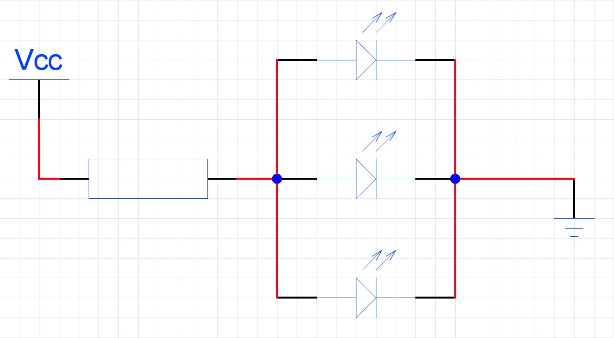
Above are the diagrams consistent turn on the LEDs. There are also ways parallel turn on the LEDs. Please note that parallel connection means a circuit in which, when the anodes and cathodes of all LEDs directly converge at two points (two beams).
Such circuits are generally not economical and unsafe for both the power supply and LEDs. In addition, the schemes parallel inclusions are more complex in calculations, demanding on the power supply, so we will use them only in special cases. Let's just see what such a circuit looks like.
Due to the voltage drop across these diodes, the voltage is no longer 5 volts to the LEDs, but much less. Limiting diodes are selected so that voltage reaches the LEDs equal their voltage drop in the open state.
Connecting LEDs to LPT Port
The universal principle of calculating the limiting resistor is described in the article "
A bit of physics. Voltage "U" is measured in volts (V), current "I" - in amperes (A), resistance "R" in ohms (ohms). Ohm's Law: U = R * I.
So we decided to turn on the LED. Consider the most popular voltages- 9, 12 V. Consider the option when there is a constant voltage at our disposal, without interference (for example, batteries, slowly taken out of the remote controls from the TV), and then consider the issue of connecting to less ideal sources (interference, unstable voltage, etc.).
All LEDs have one main electrical parameter , which ensures its normal operation. This is the current (I) flowing through the LED. The LED cannot be called two or three volt. Those who still attended physics lessons at school immediately have a logical question: if two LEDs are exactly the same and the same current flows through both, then the voltage must be applied to both. But no! The crystal manufacturing technology does not allow making two LEDs with the same, let's call it, " internal resistance"and according to Ohm's law, you can draw the appropriate conclusions. A current must be passed through the LED (according to the factory parameters) and the voltage at its terminals must be measured. This voltage will ensure the flow of the required current through the LED crystal!
Consider the most common LEDs, designed for a current of 20mA (i.e. 0.02A).
The ideal option for connecting LEDs is using a current stabilizer... Unfortunately, ready-made stabilizers are an order of magnitude higher than the LED itself, we will consider making a relatively cheap home-made one below.
Usually the average voltage (at I = 0.02 A) of the red and yellow LED is 2.0 V (usually this value is 1.8 - 2.4 V), and of the white, blue and green - 3.0 V (3.0 - 3.5 V).
So, the seller solemnly announced to you that you bought, for example, "a red LED for 2.0 V, of such and such brightness" - we will take the seller's word for now, check and if this is not the case, we will return and very politely.
Let's consider a simple option. You found at home, for example, 8 pieces of 1.5 V batteries, total 8.0 * 1.5 = 12.0 V (we take a high voltage to make it clearer), and connect one LED that we bought. Have you connected? Now throw out your LED, because it burned out, the seller told you - 2.0 V, and you stuck it in 12.0 V! We bought a new one, or better just a small bunch (photo). We look (not only look, but also use a measuring device very energetically): there is 12.0 V, we need 2.0 V, we need to put the extra 10 V somewhere (12.0 - 2.0 = 10.0). The easiest way is to use a resistor(he is - resistance). Finding out what kind of resistance you need. Ohm's law states:
U = R * I
R = U / I
The current flowing in the circuit I = 0.02 A. Resistance needs to be matched so that 10 V is lost on it, and the required 2.0 V reaches the LED. From here we find the required R:
R = 10.0 / 0.02 = 500 Ohm
Resistance voltage turns to heat... In order for the resistance to withstand the load and the heat generated does not lead to its failure, it is necessary to calculate the dissipated power of the resistance. As you know (again, back to the attendance of physics lessons), the power is:
On the resistance we have 10.0 V at a current of 0.02A. We consider:
P = 10.0 * 0.02 A = 0.2 W.
When buying a resistance, we ask the seller for 500 Ohm, with a power of at least 0.2 W (preferably more, with a margin, so that the soul is calmer, 0.5 W for example, but it should be taken into account - the more power, the more sizes). We connect the LED (not forgetting about the polarity) through the resistance and feel a wave of joy - it shines!
Now we break the circuit between the resistance and the LED, turn on measuring device and measure the current flowing in the circuit. If the current is less than 20 mA, it is necessary to slightly reduce the resistance, if it is more than 20 mA, increase it. That's all! Having received a current of 20 mA, we achieved optimal operation of the LED, and in this mode the manufacturer guarantees 10 years of continuous operation. We sit down and wait 10 years, if something goes wrong, we write a claim to the plant. As the batteries run out, the brightness of the LED will decrease. After the batteries "run out" completely, they must be put back in the remotes, pretend that it was so, or, for example, announce to everyone that a magnetic storm or excessive activity of the sun influenced the rapid death of the batteries.
We did the right thing, but usually the manufacturer indicates the average voltage for a batch of LEDs at the optimal current. And no one bothers with the exact selection of the current. Therefore, the rest of the examples will be considered on the data on the average voltage, not the current (and we will not tell anyone that this is not entirely correct!).
Now let's decide on the connection of several LEDs. We connect 2 red ones in series. 2 pcs * 2.0 = 4.0 V. The supply voltage is 12 V, therefore the extra is 8.0 V. R = 8.0 / 0.02 = 400 Ohm. P = 8.0 * 0.2 = 0.16 W.
If 6 pieces - 6 pieces. * 2.0V = 12V. No resistance required.
Similarly, for example, with blue (3.0V): 3pcs x 3.0V = 9.0V. 12.0V - 9.0V = 3.0V. R = 3.0 / 0.02 = 150 ohms. P = 3.0 * 0.02 = 0.06 W.
If we have 3 batteries of 1.5 volts each and, for example, one blue LED to which we need to supply 3.5 V in order to obtain the required current of 20 mA (0.02 A): 3 pcs * 1.5 V = 4.5 V ( supply voltage). Superfluous: 4.5 V - 3.5 V = 1.0 V. R = U / I = 1.0 V / 0.02 A = 50 ohms. P = U * I = 1.0 V * 0.02 A = 0.02 W
Now consider more difficult option... It is necessary to connect 30 pieces of red 2.0V to 12V. At 12V we can connect only 6 pieces without resistances, connect 6 pieces in series and connect - it is on. We connect 6 more pieces and connect in parallel to the first. In this case, every 6 pieces a current of 0.02A will flow. We will get 5 chains with a total current of 5 * 0.02A = 0.1A (the batteries will not last long).
It is necessary to connect 30 pieces of green 3.5V to 12V. For 12V we can connect: 12V / 3.5V = 3.43 pieces. We will not cut off 0.43 parts from the fourth LED, but connect 3 pieces + resistance: 3 pieces * 3.5V = 10.5 V. Excess voltage: 12.0 V - 10.5 V = 1.5 V. Resistance R = 1.5V / 0.02A = 75 Ohm at power P = 1.5 * 0.02 = 0.03 W. If suddenly one LED was accidentally torn out during the installation process and there were only 29 of them left, then we connect 9 chains of 3 pieces each, and one chain of 2 pieces + resistance R = 250 Ohm, P = 0.1W.
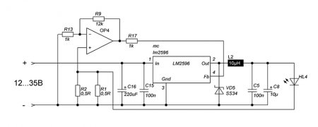
Wonderful. So we remembered a little the basics of physics. Now let's look at a more stabilized LED switching circuit. Let's put the technical problem of connection on the world's minds developing integrated circuits... Let's touch on the manufacture of a current stabilizer. It's quite simple, the main thing is to find some extra finances in your pocket. There is a KR142EN12 microcircuit ( foreign counterpart LM317), which allows you to build a very simple current regulator. To connect the LED (see figure), the resistance value R = 1.2 / I is calculated (1.2 is the voltage drop not in the stabilizer) That is, at a current of 20 mA, R = 1.2 / 0.02 = 60 Ohm. Stabilizers are designed for a maximum voltage of 35 volts. Better not to put them on like this and apply a maximum of 20 volts. With this inclusion, for example, white led at 3.3 volts, voltage can be supplied to the stabilizer from 4.5 to 20 volts, while the current on the LED will correspond to a constant value of 20 mA! At 20 volts, we find that 5 white LEDs can be connected in series to such a stabilizer, without worrying about the voltage on each of them, the current in the circuit will flow 20mA (the excess voltage will be extinguished on the stabilizer).
Important!!! A device with a large number of LEDs has a high current flow. It is strictly forbidden to connect such a device to a switched on power source. In this case, a spark arises at the connection point, which leads to the appearance of a large current pulse in the circuit. This pulse destroys the LEDs (especially the blue and white). If the LEDs operate in a dynamic mode (they constantly turn on, turn off and blink) and this mode is based on the use of a relay, then you should exclude the occurrence of a spark on the relay contacts.
Each string should be assembled from LEDs of the same parameters and the same manufacturer.
Also important !!! Temperature change the environment affects the current flowing through the crystal. Therefore, it is desirable to manufacture the device so that the current flowing through the LED is not 20mA, but 17-18mA. The loss of brightness will be insignificant, but long term service is provided.
Just connecting the LEDs and connecting them to the batteries from the remote control is not interesting. They must be soldered together and connected to some device (for example, a vacuum cleaner so that you can see the suction of each speck of dust. Here you must immediately take into account that there are 220 dangerous volts in the vacuum cleaner, and even the voltage is variable, which is not suitable for connecting LEDs. To do this, you need to make special unit power supply, but we will not discuss this topic now).
It is necessary to find a device with constant voltage and abundantly decorate it with LEDs. This is where the happy owners of personal mechanical horses (auto-moto-bike-scooter) come forward. After all, you can hang your favorite transport with LEDs so that passers-by will not doubt that you have passed by Christmas tree, but not as a means of transportation. We must immediately warn that the abuse of quantity, brightness and color is suppressed by some traffic police officers. Also, you should not, for example, make brake lights with a brightness exceeding the brightness of the headlights with the high beam- this is a little annoying for those driving behind, which can also ultimately adversely affect your body (especially on your face), but let's not get upset, because there is still space inside !!! There you can use all your imagination (for example, highlight the driver's face in blue from below, which will discourage inspection officers from checking documents).
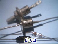
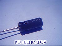
It should be borne in mind right away that the voltage in the network of a working car is not 12V, but 14.5 V. It is advisable to check this with a device when the engine is running (if, of course, there is an engine). Also, in the on-board network of the iron horse, there is a lot of interference that is not desirable, and the voltage is sometimes not very constant. To suppress interference at the input of your luminous device, you can assemble a simple circuit from two parts - a diode and an electrolytic capacitor (picture). A capacitor and a diode, like an LED, have polarity, operating voltage and current values (diode). After installing the diode and capacitor, it is necessary to measure the voltage Uout (it will not coincide with Uin) and then calculate the LED connection scheme.
If you are not sure about the constant voltage of the on-board network, you can use special integrated voltage stabilizers. They provide a constant voltage at the output at varying (reasonably) or bouncing (like a horse) input voltage.
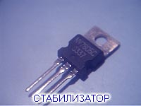
The simplest representatives are K142EN8A or KREN8A (9 volts) and K142EN8B or KREN8B (12 volts). The approximate price of such a piece is 5-15 rubles (depending on the greed of the seller). Those. you should ask the seller proudly "KRENKA, for example, for 9V", he will immediately understand everything and, seeing a major specialist in you, will not dare to cheat (foreign analogues are also sold). Microcircuits have only three legs and if you have never lost your way in three pines in your life, then it will not be difficult to understand them. We take the stabilizer with our left hand with our feet down and with the inscription towards ourselves, with the index finger right hand from left to right, poke at the legs. The first one is the entrance (+), the middle one is the building (-), the right exit (+). (Photo). You need to connect it as in the picture. At the output, we get a constant voltage of 9 or 12 volts. Based on this, we calculate, as was the case at the beginning of the article, the LED switching circuit. Why 9V or 12V? At 9V, 3 pieces of blue, green or white LEDs (at the rate of 3.0V / piece) are well connected, for 12V - 6 pieces of red or yellow (2.0V / piece) or 4 pieces of blue, green or white, i.e. e. no additional resistances are required. The microcircuit (with a large number of LEDs) must be installed on the radiator. KREN8B is designed for maximum load at 1.5A (at this current it will get very hot). Do not apply more than 35 volts to the input. The input voltage must be at least 3V higher than the output voltage, otherwise the stabilizer will not work.
In conclusion, you should pay attention to issues such as soldering and installing LEDs. This is also very important questions that affect their viability.
You should not solder LEDs with your grandfather's old soldering iron, which was heated in the stove and used to seal holes in pots. You should use a low-power soldering iron with a tip temperature of no more than 260 degrees and solder for no more than 3-5 seconds (manufacturer's recommendations). It will not be superfluous to use medical tweezers when soldering. The LED is taken with tweezers higher to the case, which provides additional heat dissipation from the crystal during soldering.
The legs of the LED should be bent with a small radius (so that they don't break, we don't need cripples!). As a result of intricate bends, the legs at the base of the case should remain in the factory position and should be parallel and not tense (otherwise the crystal will get tired and fall off the legs).
Collecting LEDs into one large luminous miracle is best on some flat sheet material(plastic, plexiglass, etc.), after having drilled holes in it the right size by the diameter of the case (you will have to master more measuring tool and a drill).
Remember that the LED is a delicate device and must be handled accordingly (when soldering, you can sing a song to make it work for a long time).
To protect your device from the car and the car from the device (after all, now it is not known which is more reliable), fuses should be installed.
In this article, I will try to explain the basic principles of powering LEDs as easily as possible. I will give examples of schemes for switching on LEDs, and also try to consider common mistakes that beginners in electronics make when choosing an LED connection scheme. If the reader knows Ohm's law, knows how to apply it in practice, then in this article he will find little useful information for yourself.
The relevance of such topics has been growing since the so-called powerful LEDs appeared, which began to be used almost everywhere possible (lighting a house, a site, a workplace, various led lights, auto lighting devices and not only). There is a high probability that a person who has never been fond of electronics will have to face such a task as connecting an LED.
An LED, unlike a conventional incandescent lamp, has technical characteristics much more various parameters... We don't need all of them, in order to choose the optimal mode for the LED when powered up and not burn it out when you turn it on for the first time. It is enough to pay attention to such characteristics as:
1. Constant forward current
2. Constant forward voltage
3. Luminous intensity
4. Glow color
Direct direct current (in the reference literature is designated as Ipr or foreign designation Io) determines what current in the continuous mode can be passed through the LED in the forward direction. The forward direction of the current is when the potential at the anode is higher than at the cathode of the LED.
In this case, we are interested in the forward direction, since the LEDs do not light up in the opposite direction.
Constant forward voltage (in the literature referred to as Upr or foreign designation VFM) determines what voltage will drop on the LED when a certain current flows through it in the forward direction.
Luminous intensity determines intensity luminous flux emitted by the LED. Everything is simple here, the more, the brighter the LED.
The glow color (red, green, blue, etc.) has a numerical representation, denoted as wavelength.
Ideally, a stabilized current source is used to power the LED, that is, it is not necessary to stabilize the voltage, as much voltage will drop on the LED as indicated in the Upr parameter. So, the classic and the most simple circuit turn on the LED.
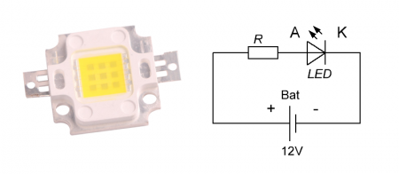
Of the advantages, only simplicity and reliability come to mind, as a rule, such a scheme is used a little for power supply high-power LEDs which serve as indicators in different devices... This scheme can be found in the most simple flashlights... The disadvantage of this circuit is low efficiency, the more the power of the LED, the greater the resistance loss, for this reason such a circuit is not used in economical devices. Resistor resistance is calculated by the formula:
R = (Ust-Upr) / I
R - Resistor resistance of the unit of measurement Ohm (ohm)
I - The current that you want to pass through the LED unit of measurement A (Ampere)
After calculating the resistance of the resistor, you need to calculate its power.
P = (Ust-Upr) * I
P - Power dissipated on resistance unit of measurement W (Watt)
Uist - Voltage of the source of the unit of measurement V (Volt)
Upr - Constant forward voltage of the LED unit of measurement V (Volt)
I - The current through the resistor in this case coincides with the current through the LED of the unit of measurement A (Ampere)
Calculation example:
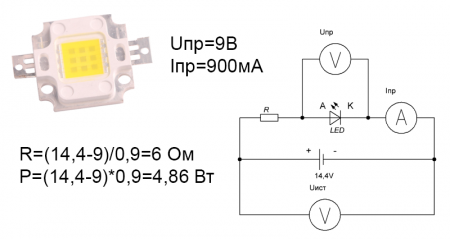
That is, when powering a 10 watt LED in this way on a resistor heat losses will be 4.86 watts. In addition, this LED switching circuit does not stabilize the current through the LED, that is, if the supply voltage changes, the current through the LED will also change. The following scheme is free from this drawback.
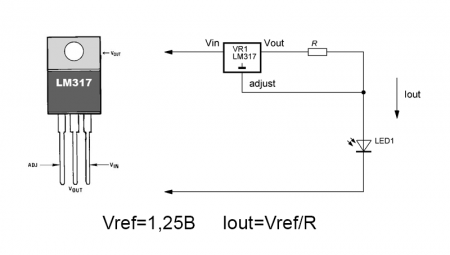
Here the role of the current stabilizer is played by the widespread integral stabilizer LM317. Unfortunately, the efficiency of this circuit is also very low. The circuit based on a PWM stabilizer is devoid of all the above disadvantages.
Such circuits are often called an LED driver, ready-made devices can be purchased at radio stores, they look like this.
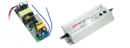
It is based on a PWM stabilizer. The efficiency of such stabilizers lies within 90%, that is, turning on a 10-watt LED through it, 1W will be released on it (driver).
And at the end, a little about the serial and parallel connection of LEDs.
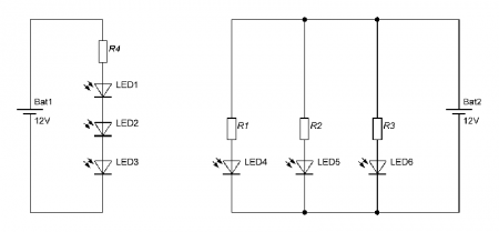
The figure on the left shows a diagram sequential inclusion three LEDs, right parallel connection three LEDs. On the Internet, you can find circuits for parallel connection of LEDs without individual current limiting resistors.
I do not recommend using such an inclusion, the direct voltage drop (even on LEDs of the same batch) is different, as a result, significantly different currents will flow through the LEDs, which will lead to the failure of the most gluttonous LED, and then all the others. That's all.
Although LEDs (lights) have been used in the world since the 60s, the question of how to connect them correctly is still relevant today.
To begin with, all LEDs are powered exclusively by direct current... For them, the polarity of the connection, or the location of the plus and minus, is important. If connected incorrectly. the LED will not work.
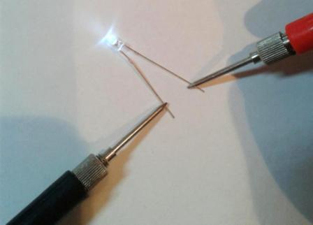
How to determine the polarity of an LED
The polarity of an LED can be determined in three ways:
N.B. Although in practice, the latter method is sometimes not confirmed.
Be that as it may, it should be noted that if the LED is not connected correctly for a short time (1-2 seconds), then nothing will burn out and bad will not happen. Since the diode itself works in one direction, but not in the opposite direction. It can burn out only due to increased voltage.
The nominal voltage for most LEDs is 2.2 - 3 volts. LED strips and modules that operate from 12 volts or more already contain resistors in the circuit.
How to connect an LED to 12 volts
It is forbidden to connect the LED directly to 12 volts, it will burn out in a split second. A limiting resistor (resistance) must be used. The resistor dimension is calculated by the formula:
R = (Upit-Upad) / 0.75I,
where R is the value of the resistance of the resistor;
Usup and Upp - supply voltage and falling;
I - passing current.
0.75 - coefficient of reliability for a LED (constant value)
For clarity, consider using the example of connecting one LED to a 12 volt car battery.
In this case:
- Usup - 12 volts (voltage in the car battery)
- Ufall - 2.2 volts (LED supply voltage)
- I - 10 mA or 0.01 A (current of one LED)
According to the above formula, we get R = (12-2.2) /0.75*0.01 = 1306 Ohm or 1.306 kOhm
The nearest standard value resistor - 1.3 kiloohm
That's not all. It is required to calculate the required minimum power of the resistor.
But first, let's determine the actual current I (it may differ from the above)
Formula: I = U / (Rres. + Rlight)
- Rlight - LED resistance:
Upad.nom. / Inom. = 2.2 / 0.01 = 220 Ohm,
from this it follows that the current in the circuit
I = 12 / (1300 + 220) = 0.007 A
The actual voltage drop of the LED will be:
Finally, the power is:
P = (Upit. - Upfall.) ² / R = (12 -1.54) ² / 1300 = 0.0841 W).
You should take a little more power than the standard value. In this case, 0.125 W is better suited.
So, in order to correctly connect one LED to 12 volts, (auto battery), you will need to insert a resistor into the circuit with a resistance 1.3 kΩ and power 0.125 watts.
The resistor can be attached to either leg of the LED.
Anyone in school, in mathematics, was a solid two - there is a simpler option. When buying LEDs from a radio store, ask the seller which resistor you will need to insert into the circuit. Do not forget to indicate the voltage in the circuit.
How to connect an LED to 220v
The dimension of resistance in this case is calculated in a similar way.
The initial data are the same. LED with consumption of 10 mA and voltage of 2.2 volts.
Only the supply voltage is 220 volts AC.
R = (Upit.-Upad.) / (I * 0.75)
R = (220 - 2.2) / (0.01 * 0.75) = 29040 Ohm or 29.040 kOhm
The closest nominal 30 kΩ standard resistor.
Power is calculated using the same formula.
To begin with, we determine the actual consumption current:
I = U / (Rres. + Rlight)
Rlight = Upad.nom. / Inom. = 2.2 / 0.01 = 220 Ohm,
and from this it follows that the current in the circuit will be:
I = 220 / (30,000 + 220) = 0.007 A
Thus, the real voltage drop of the LED will be:
Ufall.light = Rlight * I = 220 * 0.007 = 1.54 V
And finally the power of the resistor:
P = (Usup. - Ufall.) ² / R = (220 -1.54) ² / 30000 = 1.59 W)
The resistance power should be at least 1.59 W, preferably a little more. The nearest higher standard value is 2 W.
So, to connect one LED to a voltage of 220 volts, we need electrical circuit place a resistor with a nominal value 30 kΩ and power 2 watts.
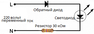
BUT! Since in this case the current is alternating, the LED will only burn in one half-phase, that is, it will blink very quickly, at about 25 flashes per second. The human eye does not perceive this and it will seem that the light is usually on. But in fact, it will still skip reverse breakouts, although it only works in one direction. To do this, you need to put a reverse directional diode in the circuit in order to balance the network and protect the LED from premature failure.
Or a light emitting diode ( English... LED Light-emitting diode) - a semiconductor device with an electron-hole junction, which creates optical radiation when transmitted through it electric current in the forward direction. In other words, it glows when current flows through it. It looks like a simple incandescent lamp, but the LED structure is more complicated. The article tells about the features of the LED, how to properly connect the LED and how to calculate the resistor for the LED.
LED Features
To understand how to properly connect LEDs, you need to understand some of the features:
- LED is powered by current... The voltage applied to the LED is irrelevant. It can be 3V or 1000V. The main thing is to withstand the required current. When there is a lack of current, the LED glows dimmer than it can. When the current is exceeded, the LED shines brighter, but it gets very hot. An LED through which more current is passed than it expects will overheat and will not work for long. In this case, it is always better to "underfill".
- voltage drop. Important characteristic LED - voltage drop. This value shows how much volt the voltage will decrease as it passes through the LED when connected in series. For example, if voltage drop across LED 3.4 volts, then with a supply voltage of 12 volts, after the first LED, 12-3.4 = 8.6 volts remains. On the second, another 3.4 volts will be lost. Remains 8.6-3.4 = 5.2V. And after the third, 5.2-3.4 = 1.8 volts will remain. This is less than the voltage drop of the LED. This means that we will not be able to power more LEDs.
- temperature regime. The LED heats up while glowing. The more powerful the LED, the more it heats up. In the case of low-power LEDs in a plastic case, their heating can be neglected. If you are dealing with super high-power, bright LEDs, you need to think about cooling.
- polarity... When connecting the LED, you must observe the polarity. If you confuse plus and minus, then nothing particularly terrible will happen, but the LED will not shine, and the current will not pass through it. The LED has 2 outputs: anode and cathode. The anode is a positive conclusion. It connects to the positive pole of the power supply. The cathode is negative. It is connected to minus (ground). Holding the LED in hand, the leads can be distinguished by their length: the anode is made longer than the cathode. Inside the LED bulb, the pins can also be distinguished by their size. The cathode is more massive and shaped like a bowl.
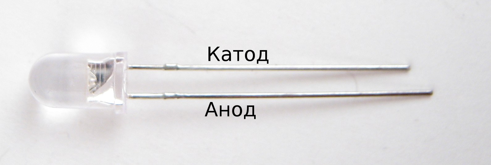
Light-emitting diode. The difference in the length of the cathode and anode is visible.
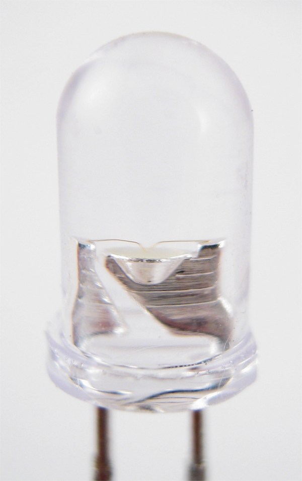
Light-emitting diode. On close-up we distinguish the cathode, which is shaped like a bowl.
The required current and voltage drop can be found in the LED specification. In our store, such information must be indicated on the product page. If you already have an LED, but you do not know its characteristics, you can assume that you need a current of 25mA, and the voltage drop is considered equal to 3V. It would seem that these parameters are ideal for connecting the LED directly to the Arduino pin. But it’s not that simple. As noted above, the LED is a current device. If an ordinary light bulb chooses a current for itself, then the LED chooses a voltage for itself. That is, if the LED requires 3V for itself, and we supply 5V to it, then the current will rise so much that the LED will burn out. This is because it is trying to keep its voltage at 3V, and the source is trying to deliver its 5V. A deadly fight begins. If the power supply is weak, and the LED manages to drop the voltage on it to the required one, it will survive, but not - the power supply will win the battle and the LED will burn out. In order to avoid problems, you need to stabilize the current for the LED. The simplest stabilizer current - resistor. We include a resistor in series with the LED, the resistor weakens the power supply, stabilizing the current. When connecting large and powerful LEDs, special currents are already used, instead of resistors. The resistor needs to be able to calculate.
Resistor calculation for LED
There is nothing complicated in calculating the resistor. From the formulas, we only need Ohm's law: the current in the circuit section is directly proportional to the voltage and inversely proportional electrical resistance this section of the chain.
To calculate the resistance of the resistor for the LED ( R) you need to know: supply voltage ( Upit), voltage drop across the LED ( Uw) and the current required by the LED ( I).
The formula is very simple: R = (Usup - Uw) / I
For simplicity of calculation, a number of "standard" parameters are accepted:
Usup = 5 V, Usv = 3 V, I = 25 mA = 0.025 A
R = 5 - 3 / 0.025 = 80 Ohm
The closest standard resistor value is 100 ohms.
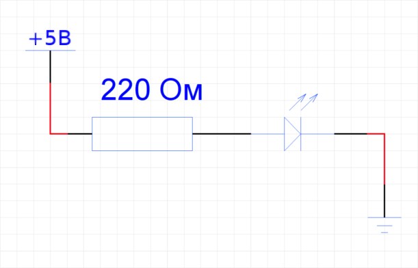
However, since you often have to deal with LEDs, the exact parameters of which are unknown, my personal recommendation is to exclude the voltage drop from the formula. This is how we get universal formula to calculate the resistor for any LED, while limiting the current with a margin and not losing much in brightness. However, if you collect lighting fixture and it is important for you to achieve the maximum luminosity of the LED, use the full formula described above. So, according to my simplified formula, the calculation will be like this:
R = 5 / 0.025 = 200 Ohm
The closest standard resistor value is 220 Ohm. We will use it to connect. The resistor should be connected between the positive pole of the source and the anode of the LED.
Now you know how to properly connect one LED. But what to do. when do you need to connect multiple LEDs to one power supply?
Connecting multiple LEDs
There is nothing complicated when connecting one LED. We just discussed this just above. But what is the right thing to do if one LED is not enough? For example, we want to connect 15 LEDs from a 12V power supply. Let's take the standard parameters of the LED for calculations. For further reasoning, you will have to stir up old Ohm again and remember that with a serial connection, the voltage is added (in this case, we are talking about the voltage drop across each LED), and the current strength remains unchanged. In parallel, the opposite is true. Now consider various options connecting LEDs.
Serial connection
The easiest way. We connect all LEDs with a garland one after another. The cathode of the first to the anode of the second, etc. The current required by the LEDs when connected in parallel does not depend on the number of LEDs and is 25mA. You also need to take into account the voltage drop across each LED. An inquisitive reader, friendly with mathematics, should now hesitate. The voltage drop is calculated as the sum of the voltage drop across all LEDs. Moreover, you need to leave a stock. The margin is worth leaving due to the fact that the LEDs are not perfect. The voltage drop fluctuates greatly even for LEDs from the same manufacturer and in the same batch. The drop depends on the temperature, and even grows as the LED ages. Our drop will be 15 * 3 = 45V. And the source is only 12 volts. This option is eliminated. We can only afford to connect 12/4 = 4 LEDs in series. With a stock of only 3 LEDs in parallel. Now you can connect a current-limiting resistor in front of the chain of three LEDs. 480 Ohm (R = 12 / 0.025 = 480) and rejoice. All three LEDs are now receiving 25mA. But the imperfection of the LEDs means that we may come across a copy that is designed for a current of only 20mA. Or a little less. Or a little more. No matter. The important thing is that our calculated 25mA will be redundant. Such an LED will start to warm up and burn out earlier than others. He will stop passing current through himself. Then all other LEDs will also go out. Daisy chain is not enough reliable circuit... One burned-out LED disrupts the operation of the entire chain.
Advantages: simple and cheap circuit, low current consumption.
disadvantages: the need for a power supply with high voltage, extremely low reliability of the circuit.
So, we managed to connect only 3 LEDs in series. But what if you want to connect all 15?
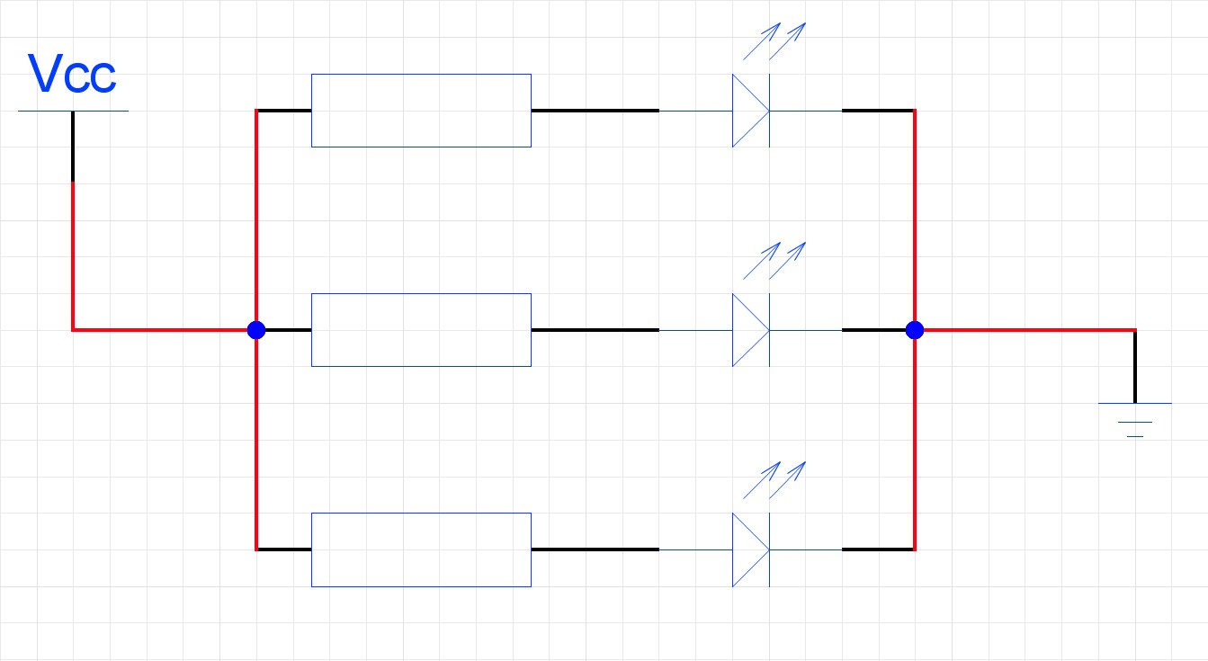
Parallel connection of LEDs
Here we have the opposite. The current strength must be multiplied by the number of LEDs, and the voltage drop must be calculated only 1 time.
Current strength: I = 0.025 * 15 = 0.375 A
We need a power supply capable of delivering a maximum current of 0.375 A. Round up to 0.35 (remember, it's better to "underfill"?). In terms of voltage, we also fit: 12 - 2 = 10. Remains with a large margin.
An inquisitive reader who stumbled a couple of paragraphs earlier may exclaim: “Wait! So why do we need 12 volts if we can get by with five? " "Can!" - we will answer him. But don't jump to conclusions, it's not over yet.
We decided that the LEDs would be connected in parallel. It is necessary to limit the current in the circuit. Let's say we don't have a special driver. Let's take a resistor. Let's calculate the required resistance according to the well-known formula: 12V * 0.35A = 4.2 Ohm. Let's connect it between the power supply and the LED anodes:
That, it would seem, is all. But there is a problem:
DO NOT DO THIS !!!
As noted above, LEDs do not necessarily have the specifications that the manufacturer claims. There is always scatter. And so we set the current to 0.35 amperes and look at the luminous line of LEDs. But they all need a different current. One, as we calculated, is 25mA, the other is 20mA, the third is 21mA, but there was a completely curved LED, it only needs 15mA. And we pass 25 through it - almost 2 times more. The LED heats up and burns out quickly. The line has become 1 LED less. We now need 35mA to power the remaining LEDs. Until it looks particularly bad. We have limited the current with a margin. We are great. But one more LED could not stand it. There are 13. Now all our current is divided not by 15, but by 13 LEDs. Each of them has 26mA. Now absolutely all LEDs operate at increased current. The next one will overheat very soon. The most persistent will receive already 29mA - 116% of the nominal. Only 2 burned out LEDs started a chain reaction. Soon the whole line will burn out, and you still won't understand why (well, or you will understand, we just sorted it out). Actually, it is easy to get rid of such a sad scenario. It is necessary to put its own current-limiting resistor to each LED. For a current of 25mA and a voltage of 12V, a 480 ohm resistor is needed. This will not save you from the problem of "crooked" LEDs, but their burnout will not affect the rest in any way.
Advantages: highest reliability.
disadvantages: high current consumption, high circuit cost.
Parallel connection of LEDs - perfect option... Always strive to connect LEDs in parallel and limit the current of each LED individually with its own resistor. If you are using led drivers(), then to each the LED needs to connect its driver. That's why parallel circuits with a lot of LEDs are getting too expensive. In reality, you have to compromise and combine LEDs into chains.
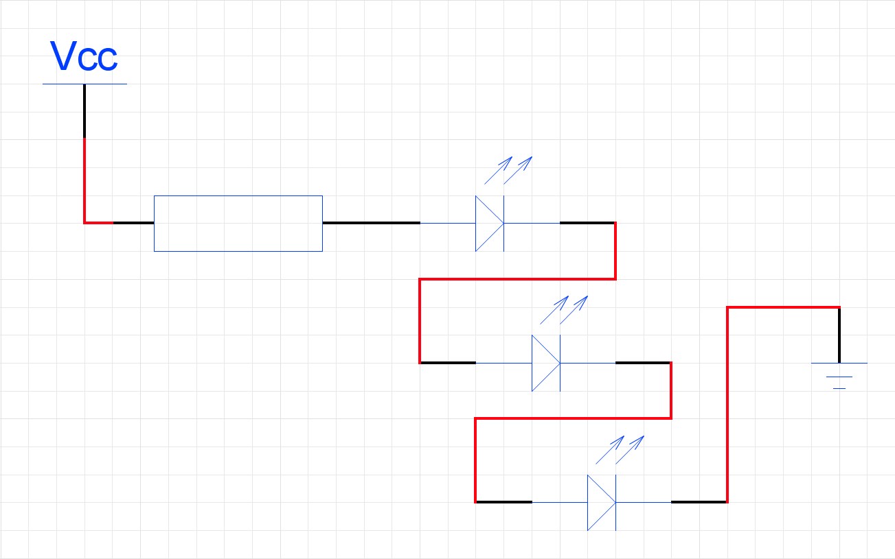
Combined way of connecting LEDs
So. Let's connect our 15 LEDs in a combined way. Let's recall the calculation for serial connection... There we found out that we can painlessly power 3 LEDs from 12 volts. Each of the 3 LEDs will require a 480 ohm resistor. This will be our chain - 3 LEDs and a resistor. Now we will connect 5 such chains in parallel. With a parallel connection, the supply voltage remains unchanged, and the amperage for each string is multiplied by the number of strings. It turns out that you need a 12V source and 5 * 0.025 = 0.125A. As you can see, this method of connection saves a lot of current.
Advantages: low current consumption with a high density of LEDs, each string is independent of the neighboring ones, thanks to the presence of its own current limiting resistor.
disadvantages: inside the chain, we get the same problems as with a normal parallel connection. If there are "curved" LEDs in the chain, it will fail earlier than others.
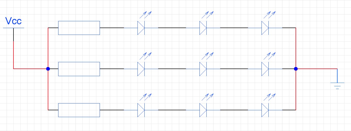
Combined LED connection. 3 strings of 3 LEDs.
conclusions
When connecting LEDs to a power source, it is preferable to use a parallel connection, supplying each LED with a separate regulator. When connecting a large number of LEDs, to reduce the cost of construction, it is possible to combine serial and parallel methods of connecting LEDs to achieve an optimal result.