The output power of a single-cycle ULF can be increased by connecting one or more lamps to the output stage lamp in parallel. Thus, at the same supply and anode voltage, the anode current and, accordingly, the output power of the cascade increase by a factor of two or more. Example parallel connection an additional lamp in the final stage of a single-cycle ULF is shown on rice. one.
Fig.1. circuit diagram single-cycle ULF on one (a) and two (b) pentodes
In the considered scheme ( rice. 1, a) uses the so-called ultralinear inclusion of the pentode, a characteristic feature of which is the connection of the cathode with a protective grid. The shielding grid of the pentode is connected to pin 2 of the output transformer Tpl, with the number of turns between pins 2 and 3 being approximately 43% of the number of turns between pins 1 and 3. The Tpl transformer is sized so that the impedance of the primary winding (pins 1-3) is equal to the value of the load resistance, determined for each lamp according to the catalog specification. So, for example, for an EL34 lamp, this resistance is approximately 3 kOhm. The auto-bias voltage is generated across resistor R3, which is shunted by electrolytic capacitor C2.
If an additional lamp (or lamps) is connected in parallel to the lamp of the ULF output stage, it will be necessary to correct the values of some elements. So, for example, when connecting one additional lamp ( rice. 1, b) the value of the resistance of the resistor R3 in the automatic bias circuit should be reduced by about half compared to the previously considered circuit ( rice. 1, a), and the capacitance value of the shunt capacitor C2 is doubled. This is due to the fact that when two lamps are connected in parallel, the cathode current doubles. It should be noted that the power of the resistor R3 should also be doubled, that is, from 5 to 10 watts. To achieve a twofold increase in output power, it will also be necessary to reduce the impedance of the primary winding of the transformer Tpl by a factor of two.
Theoretically, in a similar way, a larger number of similar lamps with almost identical parameters can be connected in parallel with the lamp of the output stage. Therefore, on sale you can find already selected pairs and even four lamps for use in the parallel connection of the ULF output stage.
As in a single-cycle tube ULF, you can increase the output power of a push-pull amplifier by connecting one or more lamps to the lamps of the output stage in parallel. With the same supply and anode voltage, the anode current and, accordingly, the output power of the cascade increase by a factor of two or more. We will explain the features of such a connection using the example of a simple push-pull power amplifier, the circuit diagram of which is shown in rice. 2.
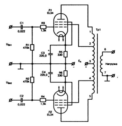
Fig.2. Schematic diagram of a simple push-pull power amplifier
This amplifier consists of two identical channels, each of which is based on the single-ended amplifier discussed earlier. An example of parallel connection of additional lamps in the final stage of such a push-pull ULF is shown in rice. 3.
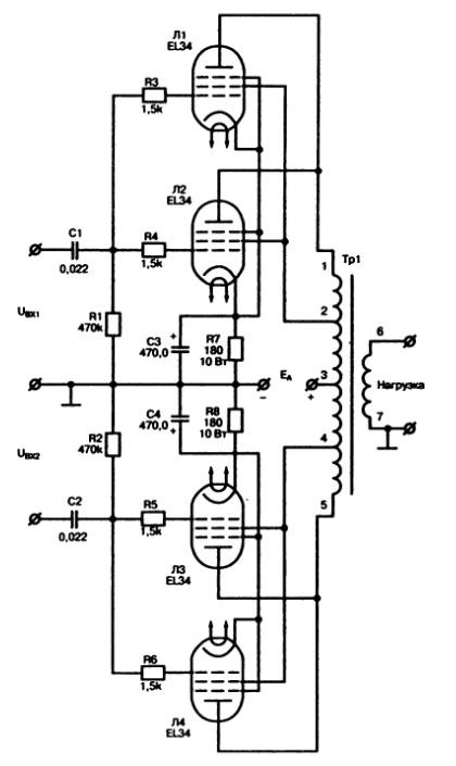
Fig.3. Schematic diagram of a simple push-pull power amplifier with lamps connected in parallel
When choosing the parameters of the elements for a push-pull lamp ULF with parallel connection of lamps, all the comments and recommendations mentioned earlier for a single-cycle circuit are valid.
In this case, the current on each of them will be the same, which makes it easier to control it. But there are times when a parallel connection is indispensable.
For example, if there is a power source, and it is necessary to connect several LED bulbs to it, the total voltage drop on which exceeds the voltage of the source. In other words, the power source is not enough for series-connected light bulbs, and they do not light up.
Then the light bulbs are connected in parallel to the circuit and a resistor is placed on each branch.
According to the laws of parallel connection, the voltage drop on each branch will be the same and equal to the source voltage, and the current may differ. In this regard, calculations to determine the characteristics of resistors will be carried out separately for each branch.
Why can't all LED bulbs be connected to the same resistor? Because the production technology does not allow to make LEDs with perfectly equal characteristics. LEDs have different internal resistance, and sometimes the differences in it are very strong even for the same models taken from the same batch.
A large variation in resistance leads to a variation in the current value, and this in turn leads to overheating and burnout. So, it is necessary to control the current on each LED or on each branch with a serial connection. After all, when connected in series, the current is the same. For this, separate resistors are used. With their help, the current is stabilized.
The main characteristics of the circuit elements
After a little thought, it becomes clear that one branch can contain maximum amount LEDs is the same as when connected in series and powered from the same source.
For example, we have a 12 volt source. You can connect 5 LEDs of 2 volts in series to it. (12 volts: 2 volts: 1.15≈5). 1.15 is a safety factor, since it is necessary to expect that a resistor will also be included in the circuit.
: I=U/R, where I will be the allowable current taken from the fixture data sheet. The voltage U will be obtained if the voltage drops on each LED included in the serial chain are subtracted from the maximum voltage of the power supply (also taken from the characteristics table).
The power of the resistor is found from the formula:
In this case, all quantities are written in the C system. Recall that 1A=1000mA, 1mA=0.001A, 1Ω=0.001kΩ, 1W=1000mW.
Today a lot online calculators, which offer to perform this operation automatically by simply substituting known characteristics v empty cells. But it is still useful to know the basic concepts.
The advantage of parallel connection of diodes
Parallel connection allows you to add 2 or 5 or 10 LEDs or more. The limitation is the power of the power supply and the dimensions of the device in which you want to use such a connection.
Light bulbs for each parallel branch are taken exactly the same so that they have the most similar values \u200b\u200bof the allowable current, forward and reverse voltage.
The advantage of paralleling LEDs is that if one of them burns out, the whole circuit will continue to work. The light bulbs will glow even when a larger number of them burn out, the main thing is that at least one branch remains intact.
As you can see, a parallel connection is quite useful thing. You just need to be able to correctly assemble the circuit, not forgetting about all the properties of LEDs and the laws of physics.
In many circuits, parallel connection is combined with series, which allows you to create functional electrical devices.
Application of Parallel Connection of LEDs
A two-terminal parallel connection scheme allows two-color light bulbs to be realized if two crystals are used. different color. The color changes when the source poles change (change of current direction). Such a scheme is widely used in two-color indicators.
If two crystals of different colors are connected in parallel in one package and a pulse modulator is connected to them, then you can change the color in wide range. Especially a lot of tones are generated when combining green and red LEDs.
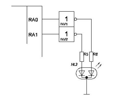
As you can see in the diagram, each crystal has its own resistor connected. The cathode in such a connection is common, and the entire system is connected to a control device - a microcontroller.
In modern holiday garlands, it is sometimes used mixed type connection in which several consecutive rows are connected in parallel. This allows the garland to glow, even if several LED sources will go out of order.
When creating lighting in a room, a parallel connection can also be used. mixed schemes are used in the design of many indicator electrical appliances and for lighting devices.
A few nuances of installation
Separately, we can say about how the LEDs are connected to each other. Each crystal is enclosed in a case from which conclusions are drawn. The terminals are often marked "-" or "+", which means, respectively, the connection to the cathode and to the anode of the device.
Experienced radio amateurs can even determine the polarity by eye, since the cathode lead is slightly longer and protrudes a little more from the case. The connection of the LEDs must be carried out strictly observing the polarity.
If we are talking Oh, then during the installation process, soldering is often used. To do this, use a low-power soldering iron, so as not to overheat the crystal in any case. Soldering time should not exceed 4-5 seconds. It is better if it is 1-2 seconds. To do this, the soldering iron is heated in advance. The conclusions do not bend much. The circuit is assembled on site from a material that removes heat well.
Let's do one more experiment. Let's take several identical lamps and turn them on one after the other (Fig. 1.9). Such a connection is called serial. It should be distinguished from the previously discussed parallel connection.
Rice. 1.9. The generator powers two lamps connected in series. The diagram shows an ammeter and three voltmeters: one measures the total voltage, the other two measure the voltage on each of the lamps
When several circuit sections (say, several lamps) are connected in series, the current in each of them is the same.
So, let's take two 100-watt lamps, the same as those considered in the previous experiment, and turn them on in series with a generator with a voltage of 100 V.
The lamps will barely glow, their glow will be incomplete. Why? Because the source voltage (100 V) is divided equally between both series-connected lamps. Each of the lamps will now have a voltage of not 100, but only 50 V.
The voltage on the lamps is the same because we took two identical lamps.
If the lamps were not the same, the total voltage of 100 V would be divided between them, but not equally: for example, one lamp could have 70 V, and another 30 V.
As we will see later, more powerful lamp receives less stress. But the current in two series-connected even different lamps remains the same. If one of the lamps burns out (its hair breaks), both lamps will go out.
On fig. 1.9 shows how to turn on the voltmeters in order to measure the voltage on each of the lamps separately.
Experience shows that the total voltage in successive sections of the circuit is always equal to the sum of the voltages in the individual sections.
The lamps burned normally when the current was 1 A, but for this it was necessary to apply a voltage of 100 V to each of them. Now the voltage on each of the lamps is less than 100 V, and the current will be less than 1 A. It will not be enough to heat the lamp filament .
We will now regulate the operation of the generator: we will increase its voltage. What will happen? As the voltage increases, the current will increase.
The lamps will glow brighter. When, finally, we raise the generator voltage to 200 V, a voltage of 100 V (half of the total voltage) will be established on each of the lamps and the lamp current will increase to 1 A. And this is the condition for their normal operation. Both lamps will burn with full heat and consume their normal power - 100 watts. The total power given off by the generator in this case will be equal to 200 W (two lamps of 100 W each).
It would be possible to turn on not two lamps in series, but ten or five. In the latter case, experience would show us that the lamps would burn normally when the total voltage was increased to 500 V. In this case, the voltage at the terminals of each lamp (we assume that all lamps are the same) will be 100 V. The current in the lamps will be and now is 1 A .
So we have five lamps connected in series; all the lamps are lit normally, each of them consumes 100 W of power, which means that general power will be equal to 500 watts.