It's hard to find any electronic device not using a stabilized power supply. Mainly as a power source for the vast majority of various electronic devices designed to operate from 5 volts, the best option will be the use of a three-pin integral 78L05.
Description of the 78L05 stabilizer
This stabilizer is not expensive () and easy to use, which makes it easier to design electronic circuits with a significant number of printed circuit boards to which an unregulated constant voltage is supplied, and each board has its own stabilizer separately mounted.
Microcircuit - stabilizer 78L05 (7805) has thermal protection, as well as a built-in system protecting the stabilizer from overcurrent. However, for more reliable work it is desirable to use a diode to protect the stabilizer from short circuit in the input circuit.
Technical parameters and pinout of the 78L05 stabilizer:
- Input voltage: 7 to 20 volts.
- Output voltage: 4.5 to 5.5 volts.
- Output current (maximum): 100mA.
- Consumption current (stabilizer): 5.5 mA.
- Permissible input-output voltage difference: 1.7 volts.
- Working temperature: -40 to +125 ° C.
Analogs stabilizer 78L05 (7805)
There are two types of this microcircuit: powerful 7805 (load current up to 1A) and low-power 78L05 (load current up to 0.1A). Foreign analogue 7805 is ka7805. Domestic analogues are for 78L05 - KR1157EN5, and for 7805 - 142EN5
Connection diagram 78L05
A typical circuit for switching on the 78L05 stabilizer (according to datasheet) is easy and does not require a large number additional radioelements.

Capacitor C1 at the input is required to eliminate RF interference when the input voltage is applied. Capacitor C2 at the output of the stabilizer, as in any other power supply, ensures the stability of the power supply at drastic change load current, and also reduces the degree of ripple.
When developing a power supply, it must be borne in mind that for the stable operation of the 78L05 stabilizer, the input voltage must be at least 7 and no more than 20 volts.
Below are some examples of using the 78L05 Integrated Stabilizer.
78L05 laboratory power supply
This circuit is distinguished by its originality, due to the non-standard use of the microcircuit, the reference voltage of which is the 78L05 stabilizer. Since the maximum allowable input voltage for the 78L05 is 20 volts, a parametric stabilizer on the Zener diode VD1 and resistor R1 is added to the circuit to prevent the 78L05 from failing.

The TDA2030 microcircuit is connected as a non-inverting amplifier. With this connection, the gain is 1 + R4 / R3 (in this case 6). Thus, the voltage at the output of the power supply, when the resistance of the resistor R2 changes, will change from 0 to 30 volts (5 volts x 6). If you need to change the maximum output voltage, then this can be done by selecting the appropriate resistance of the resistor R3 or R4.
5 volt transformerless power supply
this one is characterized by increased stability, no heating of the elements and consists of available radio components.
The structure of the power supply includes: a power-on indicator on the HL1 LED, instead of a conventional transformer - a quenching circuit on elements C1 and R2, a diode rectifier bridge VD1, capacitors to reduce ripple, a 9-volt VD2 Zener diode and an integrated voltage regulator 78L05 (DA1). The need for a zener diode is due to the fact that the voltage from the output diode bridge is approximately 100 volts and this could damage the 78L05 regulator. You can use any zener diode with a stabilization voltage from 8 ... 15 volts.
Attention!Since the circuit is not galvanically isolated from the mains, care should be taken when setting up and using the power supply.
Simple regulated power supply for 78L05
The adjustable voltage range in this circuit is from 5 to 20 volts. The output voltage is changed using a variable resistor R2. The maximum load current is 1.5 amperes. The 78L05 stabilizer is best replaced with 7805 or its domestic analogue KR142EN5A. Transistor VT1 can be replaced with. It is advisable to place a powerful transistor VT2 on a radiator with an area of at least 150 sq. cm.
Universal charger circuit
This scheme charger quite simple and versatile. Charging allows you to charge all kinds of rechargeable batteries: lithium, nickel, as well as small lead-acid batteries used in uninterruptible power supplies.

It is known that when charging batteries, a stable charging current is important, which should be about 1/10 of the battery capacity. The constant charging current is ensured by the 78L05 (7805) stabilizer. The charger has 4 charging current ranges: 50, 100, 150 and 200 mA, which are determined by the resistances R4 ... R7, respectively. Based on the fact that the output of the stabilizer is 5 volts, then to obtain an admissible 50 mA, a 100 Ohm resistor is needed (5V / 0.05 A = 100), and so on for all ranges.
The circuit is also equipped with an indicator built on two transistors VT1, VT2 and an LED HL1. The LED goes out when the battery is charged.
Adjustable current source
Due to negative feedback, following through the load resistance, at input 2 (inverting) of the TDA2030 (DA2) microcircuit there is a voltage Uin. Under the influence of this voltage, a current flows through the load: Ih = Uin / R2. Based on this formula, the current flowing through the load does not depend on the resistance of this load.
Thus, by changing the voltage supplied from the variable resistor R1 to input 1 of DA2 from 0 to 5 V, with a constant value of the resistor R2 (10 Ohm), you can change the current flowing through the load in the range from 0 to 0.5 A.
A similar scheme can be successfully used as a charger for charging all kinds of batteries. The charging current is constant during the entire charging process and does not depend on the level of discharge of the battery or on the variability of the supply network. The limiting charge current can be changed by decreasing or increasing the resistance of the resistor R2.
(161,0 Kb, downloaded: 3 935)
Good day!
Today, I would like to touch on the topic of powering electronic devices.
So, the firmware is ready, the microcontroller is purchased, the circuit is assembled, all that remains is to connect the power, but where can I get it? Let's assume that the AVR microcontroller and the circuit are powered by 5 volts.
The following schemes will help us get 5v:
Linear voltage regulator on a microcircuitL 7805
This method is the simplest and cheapest. We will need:
- Chip L 7805 or its analogs.
- Crown 9v or any other power source (charger for phone, tablet, laptop).
- 2 capacitors (for l 7805 these are 0.1 and 0.33 microFarads).
- Radiator.
Let's put together the following scheme:
This stabilizer is based on the l 7805 microcircuit, which has the following characteristics:
Maximum current: 1.5A
Input voltage: 7-36V
Output voltage: 5V
Capacitors serve to smooth out ripple. However, the voltage drop occurs directly on the microcircuit. That is, if we supply 9 volts to the input, then 4 volts (the difference between the input voltage and the stabilization voltage) will fall on the l 7805 microcircuit. This will lead to the release of heat on the microcircuit, the amount of which can be easily calculated by the formula:
(Input voltage - voltage stabilization) * current through the load.
That is, if we supply 12 volts to the stabilizer, with which we power the circuit, which consumes 0.1 Ampere, (12-5) * 0.1 = 0.7 W of heat will dissipate on l 7805. Therefore, the microcircuit must be fixed on the radiator:

The advantages of this stabilizer:
- Cheapness (Excluding the radiator).
- Simplicity.
- Easy to assemble surface mounting, i.e. no need to manufacture printed circuit board.
Minuses:
- The need to place the microcircuit on the radiator.
- There is no possibility of regulating the stabilized voltage.
This stabilizer is perfect as a voltage source for simple, low-power circuits.
Switching voltage regulator
To build, we need:
- LM 2576S -5.0 microcircuit (You can take an analog, but the binding will be different, check the documentation for your specific microcircuit).
- Diode 1N5822.
- 2 capacitors (For LM 2576S -5.0, 100 and 1000 microFarads).
- Choke (Inductors) 100 microHenry.
The connection diagram is as follows:
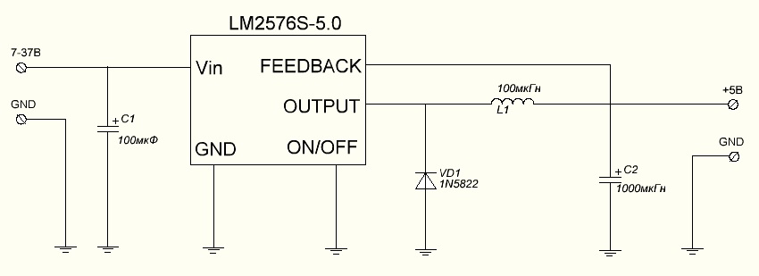 Microcircuit LM 2576S -5.0 has the following characteristics:
- Maximum current: 3A
- Input voltage: 7-37V
- Output voltage: 5V
It is worth noting that this stabilizer requires more components (as well as the presence of a printed circuit board, for a more accurate and convenient installation). However, this stabilizer has huge advantage in front of a linear colleague - it does not heat up, and the maximum current is 2 times higher.
The advantages of this stabilizer:
- Less heating (No need to purchase a radiator).
- Higher maximum current.
Minuses:
- More expensive than a linear stabilizer.
- The complexity of surface mounting.
- There is no possibility of changing the stabilized voltage (When using the LM 2576S -5.0 microcircuit).
To power simple amateur circuits on AVR microcontrollers, the stabilizers presented above are sufficient. However, in the following articles, we will try to collect laboratory unit power supply, which will allow you to quickly and conveniently configure the power supply parameters of the circuits.
Thank you for the attention!
The integrated voltage stabilizers of the KR142 series produced by the domestic industry allow using simple circuit methods to obtain stabilized voltages in a fairly wide range - from several volts to several tens of volts. Consider some circuit solutions that may be of interest to radio amateurs.
The KR142EN5A microcircuit is an integrated stabilizer with a fixed output voltage of +5 V. A typical circuit for switching on this microcircuit has already been presented in the book (see.
rice. 105). However, by slightly changing the switching circuit, it is possible, on the basis of this microcircuit, to build a stabilizer with an adjustable output voltage in the range from 5.6 V to 13 V. The circuit is shown in Fig. 148.
An unstabilized voltage of +16 V is fed to the input of the integral stabilizer (pin 17 of the DA1 microcircuit), and to pin 8 - the signal from the output of the stabilizer, regulated by the variable resistor R2 and current-amplified by the transistor VT1. The minimum voltage (5.6 V) is the sum of the voltage between the collector and the emitter completely open transistor, which is about 0.6 V, and the nominal output voltage of the integral stabilizer in its typical connection (5 V). In this case, the engine of the variable resistor R2 is in the upper position according to the scheme. Capacitor C1 smoothes voltage ripple; capacitor C2 eliminates possible high-frequency excitation of the microcircuit. The load current of the stabilizer is up to 3 A (the microcircuit must be placed on a heat sink).
Microcircuits K142EN6A (B, C, D) are integral bipolar voltage stabilizers with a fixed output voltage of 15 V. In this case, the maximum input voltage of each of the arms is 40 V, and the maximum output current is 200 mA. However, on the basis of this stabilizer, it is possible to build a bipolar regulated stabilized voltage source. The diagram is shown in Fig. 149.
By changing the voltage at pin 2 of the integral stabilizer, you can change the output voltage of each arm from 5 V to 25 V. The adjustment limits for both arms are set by resistors R2 and R4. It should be remembered that the maximum dissipation
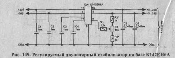
the required power of the stabilizer is 5 W (of course, if there is a heat sink).
Microcircuits KR142EN18A and KR142EN18B are adjustable voltage stabilizers with an output voltage of 1.2 ... 26.5 V and an output current of 1 A and 1.5 A, respectively. The regulating element of the stabilizer is included in the negative wire of the power supplies. The case and pinout of stabilizers of this type are similar to the KR142EN5A microcircuit.
The microcircuits are equipped with an output current overload and overheating protection system. The input voltage should be in the range of 5 ... 30 V. The power dissipated by the microcircuit with a heat sink should not exceed 8 W. A typical circuit for switching on microcircuits KR142EN18A (B) is shown in Fig. 150.
Under all operating conditions, the capacitance of the input capacitor C 1 should not be less than 2 μF. In the presence of a smoothing filter of the output voltage, if the length of the conductors connecting it to the stabilizer does not exceed 1 m, the input end
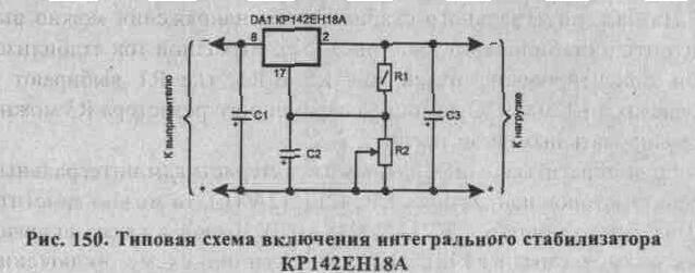
The output capacitor of the filter can serve as a stabilizer denser.
The output voltage is set by choosing the values of the resistors R1 and R2. They are related by the ratio: Uout = Uout min (1 + R2 / R1),
while the current flowing through these resistors must be at least 5 mA. The capacitance of the capacitor C2 is usually chosen to be greater than 2 μF.
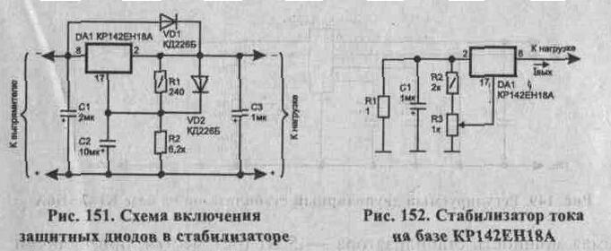
In cases where the total capacitance at the output of the stabilizer exceeds 20 μF, an accidental closure of the input circuit of the stabilizer can lead to failure of the microcircuit, since the capacitor voltage in reverse polarity will be applied to its elements. To protect the microcircuit from such overloads, it is necessary to turn on the protective diode VD1 (Fig. 151), bypassing it in the event of an emergency short circuit of the input circuit. Similarly, the VD2 diode protects the microcircuit at pin 17 in cases where, according to operating conditions, the capacitance of the capacitor C2 should be more than 10 μF with an output voltage of more than 25 V.
On the basis of an integral voltage stabilizer, a current stabilizer can also be made (Fig. 152). The output stabilization current is approximately equal to 1out = 1.5 V / R1, where R1 is selected within 1 ... 120 Ohm. The variable resistor R3 can be used to adjust the output current.
If we turn to the reference characteristics of the integral voltage stabilizers KR142EN12A (B), then we can see that they have a lot in common with KR142EN18A (B). A typical circuit for switching on the KR142EN12A microcircuit is similar to the switching circuit
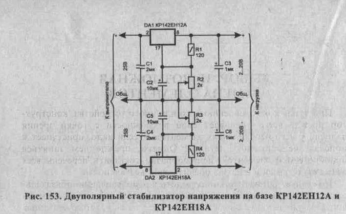
KR142EN18A, only the regulating element is included in the positive wire of the power source. Based on these microcircuits, it is easy to assemble a bipolar voltage regulator. Its diagram is shown in Fig. 153. No special comments are required here. To simultaneously change the voltage of the stabilizer arms variable resistors R2 and R3 can be replaced with one double.
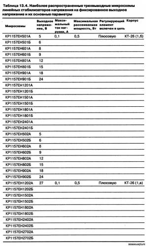
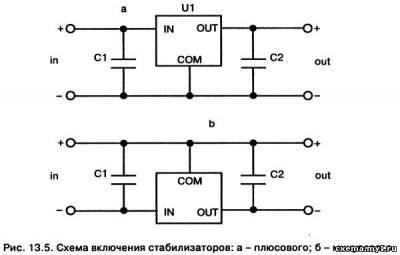
One of the important components of electronic equipment is a voltage stabilizer in the power supply. More recently, such units were built on zener diodes and transistors. The total number of stabilizer elements was quite large, especially if it was required to regulate the output voltage, protect against overload and output short circuit, and limit the output current at a given level. With the advent of specialized microcircuits, the situation has changed. Microcircuit voltage stabilizers are capable of operating in a wide range of output voltages and currents, often have a built-in protection system against overcurrent and overheating - as soon as the temperature of the microcircuit crystal exceeds the allowable value, the output current is limited. Currently, the range of domestic and foreign voltage stabilizers is so wide that it has become quite difficult to navigate in it. Placed below table. are designed to facilitate the preliminary selection of a microcircuit stabilizer for a particular electronic device. Table 13.4 presents a list of the most common three-terminal microcircuits of linear voltage stabilizers for a fixed output voltage and their main parameters on the domestic market. In fig. 13.4 is simplified appearance devices, and also indicated their pinout. The table includes only stabilizers with an output voltage ranging from 5 to 27 V - this interval fits the vast majority of cases from amateur radio practice. The design of foreign devices may differ from that shown. It should be borne in mind that information about the power dissipation during operation of a microcircuit with a heat sink is usually not indicated in the device passports, therefore the tables give some of its averaged values obtained from the graphs available in the documentation. Note also that microcircuits of the same series, but for different voltage values, may differ in terms of power dissipation. There is also another marking, for example, before the designation of the stabilizers of groups 78, 79, 78L, 79L, 78M, 79M, listed in the table, in fact, there may be one or two letters coding, as a rule, the manufacturer. Behind the designations indicated in the table, there may also be letters and numbers indicating certain design or operational features of the microcircuit. A typical circuit for switching on microcircuit stabilizers for a fixed output voltage is shown in Fig. 13.5 (a and b).
For all microcircuits of ceramic or oxide tantalum capacitors, the capacitance of the input capacitor C1 must be at least 2.2 μF, for aluminum oxide capacitors - at least 10 μF, and the output capacitor C2 - at least 1 and 10 μF, respectively. Some microcircuits allow for smaller capacities, but the indicated values guarantee stable operation of any stabilizers. The capacitor of the smoothing filter can play the role of the input if it is located no further than 70 mm from the microcircuit case.
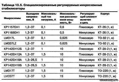
If a non-standard value of the stabilized output voltage or its smooth regulation is required, it is convenient to use specialized adjustable microcircuit stabilizers that support a voltage of 1.25 V between the output and the control pin. Their list is presented in table. 13.5.
In fig. 13.6 depicted typical scheme inclusions for stabilizers with a regulating element in the positive lead. Resistors R1 and R2 form an external adjustable voltage divider, which is included in the output voltage level setting circuit. Please note that, unlike fixed voltage regulators, adjustable capacitors do not operate without load. The minimum value of the output current of low-power adjustable stabilizers is 2.5-5 mA, and of powerful ones - 5-10 mA. In most cases of using stabilizers, the load is a resistive voltage divider Rl, R2 in Fig. 13.6. According to this scheme, stabilizers with a fixed output voltage can also be turned on. However, firstly, the current consumed by them is much higher than B-4 mA), and, secondly, it is less stable when the output current and input voltage change. For these reasons, the maximum possible stabilization factor of the device cannot be achieved. To reduce the level of ripple at the output, especially at a higher output voltage, it is recommended to include a smoothing capacitor C3 with a capacity of 10 μF or more. The requirements for capacitors C1 and C2 are the same as for the corresponding capacitors of fixed stabilizers. If the stabilizer operates at the maximum output voltage, then if the input circuit is accidentally closed or the power source is disconnected, the microcircuit is under a large reverse voltage from the load side and may be damaged. To protect the microcircuit at the output in such situations, a protective diode VD1 is connected in parallel to it. Another protective diode VD2 protects the microcircuit from the side of the charged capacitor C3. The diode quickly discharges this capacitor in the event of an emergency short circuit of the output or input circuit of the stabilizer.
Integral stabilizers voltage from series 142 do not always have complete type markings. In this case, there is a conventional designation code on the case, which allows you to determine the type of microcircuit.
Examples of decoding code marking on the case of microcircuits:
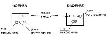
Stabilizer microcircuits with attachment KR instead of TO have the same parameters and differ only in the design of the case. When marking these microcircuits, a shortened designation is often used, for example, instead of KR142EN5A inflict KREN5A.
| Name microcircuits | U stab., V | I st max., A | R max., W | I cons., mA | Frame | Code on corps |
| (K) 142EN1A | 3 ... 12 ± 0.3 | 0,15 | 0,8 | 4 | DIP-16 | (C) 06 |
| (K) 142EN1B | 3 ... 12 ± 0.1 | (C) 07 | ||||
| K142EN1V | 3 ... 12 ± 0.5 | K27 | ||||
| K142EN1G | 3 ... 12 ± 0.5 | К28 | ||||
| K142EN2A | 3 ... 12 ± 0.3 | K08 | ||||
| K142EN2B | 3 ... 12 ± 0.1 | K09 | ||||
| 142ENZ | 3 ... 30 ± 0.05 | 1,0 | 6 | 10 | 10 | |
| K142ENZA | 3 ... 30 ± 0.05 | 1,0 | K10 | |||
| K142ENZB | 5 ... 30 ± 0.05 | 0,75 | К31 | |||
| 142EN4 | 1.2 ... 15 ± 0.1 | 0,3 | 11 | |||
| K142EN4A | 1.2 ... 15 ± 0.2 | 0,3 | K11 | |||
| K142EN4B | 3 ... 15 ± 0.4 | 0,3 | K32 | |||
| (K) 142EN5A | 5 ± 0.1 | 3,0 | 5 | 10 | (C) 12 | |
| (K) 142EN5B | 6 ± 0.12 | 3,0 | (C) 13 | |||
| (K) 142EN5V | 5 ± 0.18 | 2,0 | (C) 14 | |||
| (K) 142EN5G | 6 ± 0.21 | 2,0 | (C) 15 | |||
| 142EN6A | ± 15 ± 0.015 | 0,2 | 5 | 7,5 | 16 | |
| K142EN6A | ± 15 ± 0.3 | K16 | ||||
| 142EN6B | ± 15 ± 0.05 | 17 | ||||
| K142EN6B | ± 15 ± 0.3 | K17 | ||||
| 142EN6V | ± 15 ± 0.025 | 42 | ||||
| K142EN6V | ± 15 ± 0.5 | KZZ | ||||
| 142EN6G | ± 15 ± 0.075 | 0,15 | 5 | 7,5 | 43 | |
| K142EN6G | ± 15 ± 0.5 | K34 | ||||
| K142EN6D | ± 15 ± 1.0 | K48 | ||||
| K142EN6E | ± 15 ± 1.0 | К49 | ||||
| (K) 142EN8A | 9 ± 0.15 | 1,5 | 6 | 10 | (C) 18 | |
| (K) 142EN8B | 12 ± 0.27 | (C) 19 | ||||
| (K) 142EN8V | 15 ± 0.36 | (C) 20 | ||||
| K142EN8G | 9 ± 0.36 | 1,0 | 6 | 10 | K35 | |
| K142EN8D | 12 ± 0.48 | K36 | ||||
| K142EN8E | 15 ± 0.6 | K37 | ||||
| 142EN9A | 20 ± 0.2 | 1,5 | 6 | 10 | 21 | |
| 142EN9B | 24 ± 0.25 | 22 | ||||
| 142EN9V | 27 ± 0.35 | 23 | ||||
| K142EN9A | 20 ± 0.4 | 1,5 | 6 | 10 | K21 | |
| K142EN9B | 24 ± 0.48 | 1,5 | K22 | |||
| K142EN9V | 27 ± 0.54 | 1,5 | К23 | |||
| K142EN9G | 20 ± 0.6 | 1,0 | K38 | |||
| K142EN9D | 24 ± 0.72 | 1,0 | К39 | |||
| K142EN9E | 27 ± 0.81 | 1,0 | K40 | |||
| (K) 142EN10 | 3...30 | 1,0 | 2 | 7 | (C) 24 | |
| (K) 142EN11 | 1 2...37 | 1 5 | 4 | 7 | (C) 25 | |
| (K) 142EN12 | 1.2...37 | 1 5 | 1 | 5 | CT-28 | (C) 47 |
| KR142EN12A | 1,2...37 | 1,0 | 1 | |||
| KR142EN15A | ± 15 ± 0.5 | 0,1 | 0,8 | DIP-16 | ||
| KR142EN15B | ± 15 ± 0.5 | 0,2 | 0,8 | |||
| KR142EN18A | -1,2...26,5 | 1,0 | 1 | 5 | CT-28 | (LM337) |
| KR142EN18B | -1,2...26,5 | 1,5 | 1 | |||
| KM1114EU1A | - | - | - | - | - | К59 |
| KR1157EN502 | 5 | 0,1 | 0,5 | 5 | CT-26 | 78L05 |
| KR1157EN602 | 6 | 78L06 | ||||
| KR1157EN802 | 8 | 78L08 | ||||
| KR1157EN902 | 9 | 78L09 | ||||
| KR1157EN1202 | 12 | 78L12 | ||||
| KR1157EN1502 | 15 | 78L15 | ||||
| KR1157EN1802 | 18 | 78L18 | ||||
| KR1157EN2402 | 24 | 78L24 | ||||
| KR1157EN2702 | 27 | 78L27 | ||||
| KR1170ENZ | 3 | 0,1 | 0,5 | 1,5 | CT-26 | See fig. |
| KR1170EN4 | 4 | |||||
| KR1170EN5 | 5 | |||||
| KR1170EN6 | 6 | |||||
| KR1170EN8 | 8 | |||||
| KR1170EN9 | 9 | |||||
| KR1170EN12 | 12 | |||||
| KR1170EN15 | 15 | |||||
| KR1168EN5 | -5 | 0,1 | 0,5 | 5 | CT-26 | 79L05 |
| KR1168EN6 | -6 | 79L06 | ||||
| KR1168EN8 | -8 | 79L08 | ||||
| KR1168EN9 | -9 | 79L09 | ||||
| KR1168EN12 | -12 | 79L12 | ||||
| KR1168EN15 | -15 | 79L15 | ||||
| KR1168EN18 | -18 | 79L18 | ||||
| KR1168EN24 | -24 | 79L24 | ||||
| KR1168EN1 | -1,5...37 |