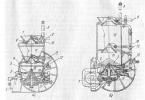
Information about the manufacturer of the Universal-3 (TSh3) lathe
The manufacturer of the Universal-3 table lathe is a plant founded in 1932.
Beginning in 1964, the plant began manufacturing erosion machines using electrophysical and chemical processing methods. Almost all tool shops of various enterprises use EDM machines and, in particular, models MA96, LF96F3, SK96F3, 4732F3M, 4733F3 and modern models SKE200F2, SKE200F3, SKE250F2, SKE250F3, SKE250F5.
Turning table machines of the Universal series
The first model of a bench-top lathe Station wagon with two round guides was developed by the organization ENIMS(Experimental Research Institute of Metal-Cutting Machine Tools). The machine was taken as a basis Unimat SL Austrian company EMCO (Over 40 years sold over 600 thousand machines of this model).
The Universal lathe was mass-produced at the enterprise Moscow Machine-Tool Plant Stanko.
Since 1968, the StankoKonstruktsiya plant began to produce a table-top screw-cutting lathe Universal-2- significantly improved Universal machine.
In the second half of the 80s, the design of the machine was significantly redesigned: starting with the model Universal-3 instead of two round guides, one larger diameter appeared in the middle of the bed and the headstock no longer detached from the bed. Several factories began to mass-produce the machine at once:
- Plant StankoConstruction: Universal, Universal-2, Universal-3 (TSh3), Universal-3m, Minitok(SKT100-01, SKT100-02, SKT100-03).
- Votkinsk Machine-Building Plant: Universal-V (TSh3-01)
- Vladimir Precision Equipment Plant: Universal-2
- Michurinsky plant Progress: TH-1, TH-1m
- Orion SKTB Nizhny Novgorod: TN-1m
- Penza Instrument Making Plant(FSUE FNPC "PO" Start "named after M.B. Protsenko") Penza: TD-180, TN-150
Universal-3 (TSh3) multifunctional screw-cutting lathe. Purpose, scope
The Universal-3 machine replaced the previously produced Universal-2... The design of the latter was completely redesigned: two round guides of the bed were replaced with one more powerful one, the design of the headstock was completely changed, etc.
This machine is a hobby-class machine and is intended for individual (domestic) use, that is, due to its design features and technical characteristics, the machine is not intended for use in production.
The Universal-3 metal lathe is designed for processing workpieces from metal, wood, all types of plastic by turning.
The Universal-3 machine is a table-top lathe and is intended for all kinds of turning works:
- grooving and boring of external and internal cylindrical, shaped and conical surfaces
- drilling holes, chamfering
- boring holes
- segment
- cutting metric threads
The spindle of the Universal-3 lathe is a hollow steel part, with an internal hole of 15 mm for processing bar material, mounted on 2 roller bearings in the front and rear supports of the headstock.
The spindle receives 9 speeds from a 370 W electric motor through a pulley drive.
The threaded end of the spindle can also be fitted with a collet with various internal bores.
Unlike the Universal-2 machine, the spindle cannot move along its axis.
The caliper with the cutter installed on it moves along the longitudinal guides by 215 mm and along the transverse ones by 90 mm.
A distinctive feature of the machine is its wide versatility and the possibility of readjustment using devices that allow you to perform the following work:
- drilling holes
- milling planes, recesses, grooves, etc.
- grinding and polishing
- sharpening of various roaring and household tools
- sawing sheet material, planks, boards with a circular saw
- contour sawing with a jigsaw
- planing of planes of slats, bars and boards using a planer
- coil springs
- tapping with dies and taps with manual spindle rotation to others
With the help of simple devices made on the machine by the amateur himself, you can also perform other work.
The traditional visual layout of the machine in combination with a proven kinematic scheme allows you to confidently provide turning with accuracy class "H" for a long service life.
In comparison with small-sized machines offered on the market, it is easy to operate, reliable and durable.
Due to the wide capabilities of the machine, its use at home is of great interest and, when mastering labor skills, working on it will bring great pleasure.
The machine can also be widely used in school circles, clubs, pioneer palaces, pioneer camps, etc. for the manufacture of radio components, aircraft and ship models, small original household items and decorations, individual toys, parts, games, etc.
The machine operates on a 220 V, 50 Hz single-phase AC network.
The cast bed, rigid hardened guides and the main body parts of the machine are made of high quality modified cast iron with aging and ensure high accuracy of the workpiece.
In the Universal-3 machine, a device is installed that provides a change in the direction of movement of the support without changing the direction of rotation of the spindle and its stopping.
Accuracy standards for turning operations:
- Out-of-roundness of the processed sample-product with dimensions Ø30 x 125mm, no more - 20
- Taper of the processed sample-product with dimensions Ø30 x 125mm, no more - 30
- Roughness of the machined surface Ra, μm - 1.25 (at finishing conditions)
The technological capabilities of the Universal-3 machine can satisfy both a professional with the most versatile interests and an amateur.
Machine tool Universal-3 manufacturer - plant StankoConstruction Moscow city.
- when drilling - drills 2300-0181 (GOST 10902-77)
- for milling work - end mills 2220-0037 (GOST 17025-71): Cutting speed no more than 15 m / min.
- Surface grinding device: Cup grinding wheel 18 (see Fig. 4) with the help of screw 19 and washer 20 is attached to the mandrel 15. Under the wheel and under the washer are placed spacers 21 made of cardboard. The mandrel with the circle installed on it is screwed onto the front end of the machine spindle. Then, a protective ring 17 is put on the casing 14, located above the spindle, and screws 16 with washers are fixed on it through the grooves designed to adjust the position of the protective ring relative to the grinding wheel.
Standard delivery set
The standard delivery set of the Universal-3 benchtop machine includes:
Accessories:
- Three-jaw chuck 7100-0001 with flange and ring, assy
- Reverse jaw set and 3-jaw chuck wrench 7100-0001
- Drill chuck with key 6-B10 or 10-B16 GOST 8522
- Shank to drill chuck
- Tool holder movable
- Fixed tool holder
- Center revolving
- Center thrust 2pcs.
- Driver cartridge
- Bar with screws and clamp assembly (for boring work)
- Collet F6
- Collet F8
- Surface grinding device
- Vise
- Sharpening device
- Circular saw device
- Leash for woodworking
- The assistant
- Jigsaw device
- Screen
- Chuck cover
- Polyethylene oil can
Tool:
- Open-end wrench
- Socket wrenches GOST11737
- 7812-0373 40HFA H12x1 S = 4
- 7812-0374 40HFA H12x1 S = 5
- 7812-0375 40HFA H12x1 S = 6
- Chisel
- Key for square S8
- Socket wrench S10х13
- Key handle S10х13
- Key for square S7
- Straight through cutter (high-speed steel)
- Straight cutter right with carbide plate
- Scoring cutter (high-speed steel)
- Boring cutter (high-speed steel)
- Cutting cutter (high-speed steel) 2 pcs.
- External thread cutter (high-speed steel)
- Internal thread cutter (high-speed steel)
- Circular saw 3420-0356 GOST 980-80
- Jigsaw saw L = 125 mm. TU 205.07.359-81 5 pcs.
- Spiral drill Ø6.0 GOST 10902
- End mill with a cylindrical shank Ø6.0 GOST 17025
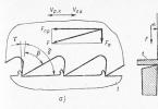
Dimensions of the working space of the Universal-3 lathe. Caliper sketch

Dimensions of the working space of the Universal-3 machine. Caliper sketch

Drawing of the spindle of the Universal-3 screw-cutting lathe


Photo of the end of the spindle of the Universal-3 lathe


List of components of the Universal-3 lathe
- drive unit
- bed
- spindle head
- support
- tailstock
- electrical box

The list of controls of the Universal-3 screw-cutting lathe
- feed motion control handle (turning on the mechanical longitudinal feed of the support to the left, right and turning it off)
- main motion control handle (turn on the forward rotation of the spindle, stop and turn on the reverse rotation)
- handwheel for lateral movement of the caliper
- handwheel for tool post movement
- quill clamping handle
- handwheel for moving the quill
- handwheel for longitudinal movement of the caliper
- button for turning off the power of the electrical equipment of the machine (red)
- power button for the electrical equipment of the machine (black)
The device and operation of the Universal-3 lathe
A hollow cylindrical guide is fixed on the machine bed. It is a common base for the main units of the machine: spindle head, support, tailstock. Another common base for these assemblies is the flat bed guide.
In the front part of the bed, under the casing, there is a lead screw for the longitudinal movement of the caliper.
A bracket is installed on the left wall of the headstock. The electric motor of the machine drive is fixed on it.
Under the casing covering the bracket are the spindle rotation drive pulleys and the feed drive mechanism.
Additional accessories for the Universal-3 multifunctional lathe. Setting up the machine for different types of processing
The machine is supplied in a lathe version. Additional accessories included in the delivery set (see table 7) are used to carry out other machine versions with the help of simple changeovers: milling and drilling, grinding, planing, etc.
The following describes the design of the accessories and shows how to set them up for different types of processing.
Tool holders
The delivery set includes two tool posts: movable and fixed.
Tapered surfaces can be machined with a movable tool holder mounted on a carriage. The fixed tool post is attached to the slide of the support by means of a screw and a lock that fits into one of the T-shaped grooves of the slide. There are two screws in the carriage, which, using the same crackers, attach the carriage to the caliper slider.
In general, the carriage can be installed in any of the grooves of the support slider in accordance with the setup requirements.
To process tapered surfaces, the carriage should be installed on the slider so that the initial zero line of the carriage scale coincides with the line on the left end of the slider. Such an installation is carried out using one screw in the carriage bases, which is screwed into a specially provided for this purpose threaded hole located on the upper plane of the slider between two T-shaped slots. The scale division of the carriage is 1 °.
ATTENTION! After turning the carriage to the required angle, it is necessary, in order to avoid an accident, to securely fix it with a fastening screw, as described above.
Collet clamp
The clamp consists of a collet, a nut and a ring, the collet is inserted into the tapered hole of the spindle, and the nut is threaded onto the spindle. With the help of this nut, a workpiece or a cutting tool inserted into its inner cylindrical hole is clamped in a collet moving along its axis.

Milling and drilling device
The device (Fig. 4) is a rack 3, along the guides of which the table moves 4. The movement is carried out by rotation, the handwheel I, rigidly connected to the lead screw 2. The workpiece is attached to the table with clamps 11 using pins 10, nuts 9, screws 8 and crackers 7 included in the T-shaped slots of the table. In order to set up the machine for milling or drilling work, it is necessary to fasten the stand to the machine support using strips 6 and screws 5, as shown in Fig. 4.
The end mill or drill is clamped in a collet chuck or in the 12 special drill chuck included in the delivery.
The chuck 12 is connected to the spindle using a special shank 13, also included in the delivery.
In addition to clamps, a vice can be used to secure the workpiece, which are fastened with screws to the table of the milling and drilling device with the help of crackers. There are two prismatic grooves on the stationary jaw of the vise, which make it possible to conveniently fix cylindrical parts.

Kinematic diagram of the Universal-3 lathe
Description of the kinematic diagram of the Universal-3 screw-cutting lathe
Main drive chain
In this circuit, the rotation of the spindle is carried out from the electric motor 3 through the V-belt transmission (see Fig. 3). 9 working spindle speeds are provided.
Two stages (200 and 300 rpm) can be obtained if the pulley 13, rigidly sitting on the motor shaft, is connected by a belt with an intermediate pulley 1, and that, in turn, along the stream "a" - with a pulley 2 freely rotating relative to the motor shaft ... From pulley 2 along one of two free grooves - "in" or "c" - the rotation is transmitted directly to the pulley 9, rigidly connected to the spindle.
One stage (650 rpm) is obtained by transferring rotation from pulley 13 directly to pulley 9, bypassing intermediate pulleys 1 and 2.
Two more steps (525 and 1000 rpm) can be obtained if a replaceable pulley 12 is put on the pulley 13 so that the end on which the cams are located is facing outward. From the pulley 12, as in the first case, the rotation is transmitted to the intermediate pulley 1, and from it along the stream "b" to the pulley 2, which transfers the rotation to the pulley 9 along the streams "a" or "c".
The remaining four steps (1200, 1700, 2800 and 3200 rpm) are obtained if the motor shaft is connected to the pulley 2 through the pulley 12 using cams on one of the ends of the latter. Now, along any of the four streams, rotation can be transmitted to the pulley 9.
Note: The 1200 rpm stage can be obtained without connecting the motor shaft to the pulley 2.
Feed drive chain
The movement of the caliper to the right and to the left is carried out using the lead screw 14.
Rotation to the lead screw is transmitted directly from the spindle by gear II rigidly fixed to it.
Through the gear wheel 10, the rotation is transmitted to the gear wheels 8 and A, then to the intermediate roller 5. There are two options for transferring rotation to this roller: the first option (indicated by the number I in the diagram) - through the gear block B-C and the wheel G and the second (indicated by the number II in the diagram) - through gears B and B.
The first option is used for feeding in conventional turning, the second for threading. A gear wheel 6 is rigidly connected to the roller 5. From this wheel to the wheel 7, fixed at the left end of the lead screw, rotation can be transmitted either through a pair of gear wheels 15 and 16 - and then the caliper will move to the left, or through the gear wheel 17, which will provide moving the caliper to the right. All three wheels (15, 16 and 17) are mounted on a turning device 4 (see D-D) and are in constant engagement with a gear wheel 6 (central). Thus, it is possible to move the slide both to the right and to the left with the same direction of rotation of the spindle.
It is also possible to turn off the feed of the slide without stopping the spindle rotation. This is ensured by the disengagement of gears II and 10 using the same rotary device 4 and spring 18.
ATTENTION! In order to avoid breakage of the gear wheels of the feed drive chain, the inclusion and switching of the direction of movement of the caliper should be performed with a non-rotating spindle.
The movement of the tailstock quill and the lateral movement of the caliper are carried out by handwheels through the corresponding screw pairs, as shown in the kinematic diagram.


Electrical equipment of the Universal-3 lathe. General information
By the method of protection against electric shock, the electrical equipment of the machine belongs to class I, i.e. has working insulation, a grounding element and a wire with a grounding conductor for connection to the power supply and grounding.
The schematic electrical diagram of the machine is shown in Fig. 14, the list of electrical equipment elements is shown in Table 4. The electrical equipment is located in a separate box (see Fig. 1, item 6). The box is closed with a lid. The cover is secured with two screws, one screw is located in the center of the cover under the rubber mat, the other secures the cover to the frame, ensuring the cover is grounded.
Description of the work of the wiring diagram of the Universal-3 lathe
Power supply of electrical equipment is carried out from a single-phase AC network with a voltage of 220 V, a frequency of 50 Hz.
The start and stop of the electric motor is carried out using the KV relay (see Fig. 14), which is controlled by the buttons SB2 (start) and SB1 (stop). At start-up, the KV relay turns on and becomes self-powered, connecting the electric motor to the network with its contacts and providing zero protection, i.e. shutdown of the electric motor in the absence of voltage in the network. The overload protection of the electric motor is performed by the start-up relay A, which breaks the starting circuit, which turns off the KV relay. Restarting is possible only after 15-50 s, i.e. after the return of the thermal protection elements of the start-up relay A to its original position.
When starting the electric motor, an increase in its starting torque occurs due to the connection of the starting capacitor C1 by the contacts of the starting relay A in parallel with the operating capacitor C2. After accelerating the electric motor and decreasing the starting current, the capacitor C1 is turned off.
The reversal of the electric motor is carried out using the SA switch, which, when the handle is in the middle (vertical) position, ensures that the electric motor is switched off, i.e. it stops even when the KV relay is on. The handle should be left in neutral
Universal-3 desktop screw-cutting lathe. Video clip
Shown is the Universal-3 machine in which the capacitor bank and the starting relay are replaced by a frequency converter.
Of the advantages, smooth speed control (from hundreds to about 4000).
Of the minuses, the low torque at low revs.
Technical characteristics of the Universal-3 machine
| Parameter name | Station wagon | Universal-2 | Universal-3 | Universal-3m |
|---|---|---|---|---|
| The main parameters of the machine | ||||
| The largest diameter of the workpiece over the bed, mm | 100 | 125 | 150 | 150 |
| The largest diameter of the workpiece over the slide, mm | 50 | 60 | 90 | 90 |
| The greatest length of the workpiece in the centers (RMTs), mm | 150 | 180 | 250 | 250 |
| Recommended turning depth in one pass, mm | ||||
| Maximum turning depth in one pass, mm | ||||
| Maximum tool holder size, mm | 8 x 8 | 8 x 8 | 8 x 8 | 8 x 8 |
| The largest diameter of drilling in steel, mm | 6 | 6 | 6 | 6 |
| Headstock. Spindle | ||||
| Diameter of the through hole in the spindle, mm | 10 | 10 | 15 | 15 |
| Attaching the chuck to the spindle | M20 | M20 | M27x2 | M27x2 |
| Spindle taper size | Morse code number 1 | Morse code number 2 | Morse code number 2 | Morse code number 2 |
| Number of steps of frequencies of direct rotation of a spindle | 10 | 11 | 9 | 9 |
| Frequency of direct rotation of a spindle, rpm | 160..2890 | 140..3000 | 200..3200 | 200..3200 |
| Chuck diameter, mm | 80 | 80 | 80 | 80 |
| Headstock sleeve travel, mm | 25 | 30 | - | - |
| Caliper (cross slide). Feed | ||||
| The greatest longitudinal movement of the carriage of the support, mm | 160 | 160 | 215 | 215 |
| Longitudinal movement of the support by one division of the limb, mm | 0,05 | 0,05 | ||
| The greatest transverse movement of the support, mm | 55 | 60 | 90 | 90 |
| Caliper movement transverse by one division of the limb, mm | 0,05 | 0,05 | ||
| The greatest displacement of the incisor slide (upper support, compound slider), mm | - | - | ||
| The division of the scale of rotation of the incisor slide, degrees | - | - | 1 | 1 |
| Limits of longitudinal working feeds of the support, mm / rev | - | 0,05..0,175 | 0,05..0,175 | 0,05..0,175 |
| Limits of steps of the cut metric carvings, mm | - | 0,2..2 | 0,2..2,5 | 0,2..2,5 |
| Tailstock | ||||
| The greatest movement of the quill, mm | 20 | 20 | 30 | 30 |
| Tailstock taper | Morse 1 | Morse 1 | Morse 1 | Morse 2 |
| Electrical equipment | ||||
| Rated supply voltage, V | 220V 50Hz |
We will show you a purchase that will help you solve an important issue. A year earlier, a Chinese-made lathe was purchased. He had some problem. It was not possible to adjust the spindle speed. Therefore, we made adjustments to the design of the machine.
For this was purchased frequency converter... With it, you can change the frequency of the current directed to the propulsion system of the machine. The device operates on a 220-volt single-phase network, and supplies three phases of 220 volts to the engine. Converter for 220 volts has a large number of control keys. How does the frequency converter work? It is capable of reversing, starting and shutting down the unit, adjusting the speed of the engine unit with the help of the remote control and switches.
Adjusting the frequency converter
- With the first set-up, we have the option of simply starting the propulsion system of the lathe in a bench-top version. The launch is carried out at a frequency of 10 hertz. Using a variable transistor, it is possible to change the speed of the propulsion system by increasing the frequency of the current to 400 hertz.
- In order to change the direction of rotation of the motor device of the lathe using the converter, the device must be turned on. We turn on the toggle switch that changes the rotation of the propulsion system torque. At the same time, the engine began to rotate in the opposite direction.
- Now let's start considering the possibility of revolutions of the engine of a lathe in a desktop version due to toggle switches, without using a rheostat. For this purpose, only the required speeds are switched on and off. When the frequency converter is switched to the "on" mode, the device generates 10 hertz. The toggle switches are set in such a way that when they are started, the current frequency increases by 5 hertz. As a result, we are able to adjust the speed of the spindle of the machine at the expense of a frequency drive without a mechanical transmission.
Working conditions of the converter for the lathe
- The converter is capable of operating in wide temperature ranges from +35 to -20 degrees. But, it should be borne in mind that the selection of the converter is carried out not in terms of power, but in accordance with the current of the propulsion system.
- If the spindle runs at low speeds, then additional cooling elements should be mounted on the engine, because the standard fan will not cope with the load. To maintain the required torque at low revs, vector acceleration is used.
- An encoder is installed on the electric motor, adjustment is made in a closed loop, the torque is stably maintained. From time to time, at the enterprise, asynchronous machines with an encoder are installed on lathes.
Electronic components of the chastotnik
Chinese manufactures already have technologies for the production of propulsion units and software. For the factory version, this is acceptable, but for domestic conditions it is too expensive.
New models of asynchronous motor units have more complicated control. When starting asynchronous engines of increased power, high current overloads occur. Significant torque can destroy the bearings and mountings of the propulsion system. With a sudden shutdown of the engine, overvoltage and accidents in the electrical installation may occur. Therefore, when controlling electric motors, frequency converters are used.
The author of the Simple Stuff blog made a review of a recently purchased second-hand lathe tv 16. This is a small bench-top lathe, all the main components are present on it, and even a few cutters remain in the kit.
Various machines and tools in this Chinese shop.
There is an automatic forward and backward feed in this machine, the gears of which feed are regulated. The only thing is that there is no additional set of gears for cutting various threads. With this set, you can only slightly adjust the feed rate.
The machine is mounted on a massive metal base. An electric three-phase motor is installed inside, belts and pulleys with which you can adjust the spindle speed. Powered by Chinese HT1000B. They can power motors up to 1.5 kW. That is, the frequency converter itself is powered by 220 volts of single-phase voltage, and at the output it gives out a three-phase voltage of 220 volts as well. Therefore, the master switched the motor according to the triangle scheme so that it worked at 220 volts. 3 phases, 220 volts.
The former owner reported that there was a small breakdown. The regulator did not work, but after soldering the variable resistor works. This frequency converter still has a function - the ability to install an additional variable resistor, it is external, which allows you to directly control the speed. I also installed three buttons "forward", "backward" and "stop", that is, turn on, add revolutions and the cartridge rotates in one direction. We stop, then it rotates in the other direction and you can add revolutions.
Budget frequency converter for a lathe
The frequency player surprised me because it turned out to be very budgetary compared to others on the Internet. I downloaded the instructions for it on the Internet, in English. But for those who have already connected chastotniki and programmed, it will not be difficult to figure it out. There are various functions - braking and acceleration.

I installed a lamp, which is also turned on by a toggle switch. Movable at 12 volts, it can be adjusted and illuminated the work area.
Checking machine operation
Let's try to install some workpiece, sharpen it. Let's see how the machine works. The machine initially vibrated slightly and left a wave on the workpiece from the cutter. After sitting on the forums, I studied this issue, tightened the spindle nut, tightened the tapered bearings in the headstock. Apparently, this was the reason, the vibration has stopped and now the machine sharpens quite normally. Let's set the 20th circle, let's see how the machine works. We turn on the feed, add revolutions. Such processing is obtained. The owner is generally satisfied with the purchase, because for those who work in the workshop, the need for
The use of frequency converters to control the speed of the lathe spindle, control the rotation speed of the main drive of the grinding machine, control the speed of the traction element of the drawing line, control the line for longitudinal and cross cutting of sheet metal.
Work: Frequency converter 1 regulates the rotation speed of asynchronous motor 2 of the main spindle drive 3. The system operates in a closed loop with feedback but the rotation speed. The rotation speed is measured by a pulse encoder 6. The operating mode of the variable frequency drive is set from the control panel 5. The cutter 4 moves smoothly from right to left along the rotating part.
Before the introduction of a variable frequency drive, the engine speed was constant, and the spindle speed could only be changed discretely using the gearbox.
Equipping the processing machines with a frequency-controlled electric drive allows us to satisfy the most stringent and contradictory requirements imposed by the technology of processing various materials. The use of a variable frequency drive makes it easier to control the machine due to the possibility of smoothly changing the number of spindle revolutions without stopping it, and to expand the range of revolutions. The use of a gearbox and a variable frequency drive allows you to optimally set the spindle speed and get the maximum torque at low speeds.

Increasing the spindle speed control range to a value of 1: 100 or more, and thereby expanding the capabilities of the machine for processing parts from various materials.
improving the quality of processing in detail and reducing the number of breakages of the cutting tool due to the precise maintenance of the spindle rotation speed,
reducing the number of equipment breakdowns by reducing shock loads on the electric drive and mechanical transmission during start-up and shutdown.
The problem to be solved: direct control of the grinding wheel rotation speed to ensure the required quality of grinding of various materials.
Options: the speed of rotation of the wheel rpm., the discrepancy in the speed of rotation of the wheel leads to a violation of the quality of grinding. For example, sanding soft materials at high speed will “burn” the surface and the plastic will melt.
Regulation of the wheel rotation speed by means of a frequency converter allows:
expand the capabilities of the machine for processing various raw materials,
select the optimal wheel rotation speed to improve the quality of processing of each material.
Machine diagram. The workpiece 1 to be machined is fixed horizontally on the worktable 2. The worktable is moved relative to the rotating wheel using handles 3 and 4. The grinding wheel 8 is rotated by a high-speed electric motor 5 at the speed required for a given material. Speed control is achieved using a frequency converter 6. The preset required speed is set from the control panel 7.


Drawing is widely used for the production of bar metal, wire, pipes and other metal products of constant cross-section. This is a continuous process of metal deformation by pulling workpieces through one or more calibrated holes (dies) on the drawing mills.

Work: The original wire coil is placed on the unwinder 1. Through the rotating rollers 2, called the descaler, the wire is fed into the grease application 3. The wire is then pulled through the tapered die 4 (shown by the arrow below).
Three or four turns of wire are laid on the drive drum of the drawing machine 7. The drum is driven by an asynchronous motor 6, which is controlled by a frequency converter 8. The wire tension force (moment on the drum shaft) is measured by a tension sensor 5. The feedback signal from the tension sensor is fed to the input of the frequency converter. Thus, a closed loop is built for controlling the torque on the shaft of the pulling drum.
The specified torque on the shaft is set on the front panel of the control cabinet 9. In this case, in the steady-state operation of the drawing mill, the linear speed of the wire at the exit from the die is kept constant. From the exit of the drawing machine through the stacker 14, the wire is fed to the take-up reel 12 of the winding machine. The stacker makes a reciprocating motion, and ensures an even laying of the wire.
The speed of rotation of the drive motor 13 of the winding reel is controlled by the frequency converter 10, so that the speed decreases with an increase in the diameter of the winding. The winding diameter is determined by the feedback sensor 11. The feedback sensor is a variable resistor, the resistance of which changes in proportion to the angle of rotation of the pressure roller.
The main purpose of using the frequency converter: expanding the capabilities of the drawing mill for processing metal of various strengths (hard and low-plastic, difficult to deform, low-strength) and a wide range of sections. This is achieved by smoothly adjusting the drawing speed in the range of 1: 1000 and more.
The use of a variable frequency drive, in addition, provides:
automation of the work of the drawing mill at variable load due to the coordinated regulation of the drive motors,
elimination of wire bursts due to smooth start-up and braking of the drawing machine drum,
improving the quality of the finished product due to the precise control of the drawing speed.
The use of automated cutting lines becomes necessary almost always when working with sheet metal: the manufacture of metal structures, metal profiles, body parts, etc. Frequency converters are part of the control systems of such lines.

In a typical cutting line, several converters can be installed: one of them 1 controls the electric drive 11 of the unwinding device 10, the other 2 - the electric drive 6 of the sheet broach, the third 3 - the electric drive 4 of the reeling device 5. General control is carried out from the control cabinet panel 9. For cutting metal circular shears 8 and cross-cut shears 7 are used.
In slitting lines, an electric drive with a frequency converter provides strip broaching, smooth start / braking. The speed of the lane is maintained automatically by changing the loop in the loop pit 12 using the speed sensors.
In the cut-to-length lines (there is no winding device and converter 3, a receiving table 13 is installed in place of the loop pit) an electric drive with a frequency converter and a pulse encoder provides strip advance, smooth start-up, braking and exact stop of the strip at the time of cutting.
The main purpose of using a frequency converter: exact stop of the strip at the moment of cutting in cut-to-length lines and maintaining a given strip speed in slitting lines.
The use of a variable frequency drive also provides:
provides high performance of metal cutting lines.
reducing labor costs and reducing metal waste.
The cutting process is controlled centrally from the control cabinet. The operator on the control panel sets the number and length of the produced strips and sheets.
We will show you our purchase to solve an important issue. We bought a Chinese lathe a year ago. It had the following problem. It is impossible to smoothly change the spindle speed. We decided to make changes to the design of the lathe.
Frequency converter instead of gearbox
For this purpose, a frequency converter was purchased. It allows you to change the frequency of the current supplied to the electric motor of the lathe. The device operates on a 220 volt single-phase network, and outputs it to the electric motor. There are many control buttons on this device. How does a frequency converter work? The device allows using the control panel with four switches in a row to reverse, turn on and off the machine, change the engine rotation speed.
Why are there many switches? Simplified ones can be done as follows. The device allows you to make multi-stage speeds. This device has five outputs, for different types of switching on and off the engine, for different revolutions.
Adjusting the frequency converter
- In the first setup, we can do a simple turn-on of the table lathe motor. The start takes place at a frequency of 10 hertz. With a variable resistor, you can change the speed of the motor by increasing the current frequency to 400 hertz.
- If we need to change the direction of rotation of the lathe motor using a frequency converter, then first turn off the device. Turn on the toggle switch for changing the rotation of the engine torque. As a result, the engine began to rotate in the opposite direction. With a frequency converter, you can also change the direction of rotation of the motor.
- Now we will consider the possibility of changing the rotation of the motor of a table lathe using toggle switches, without using a rheostat. For this, we only use the switching on and off of the corresponding speeds. To do this, we transfer the frequency converter to the "on" position, the device gives out 10 hertz. The toggle switches are set so that when they are turned on, the current frequency increases by 5 hertz. As a result, we can control the rotation speed of the lathe spindle using a frequency converter without a mechanical transmission.
Working conditions of a frequency converter for a lathe
- The frequency converter operates in a wide temperature range from +35 to -20 degrees. However, it must be borne in mind that it is necessary to choose a frequency converter based not on the power, but on the motor current. It is impossible to count on any engine frequency. Not every motor can operate at 100 hertz, although the frequency converter produces them without problems. For example, a 0.55 kW motor at 2800 rpm may stop at 75 hertz and operate normally at 65 hertz. In theory, the motor can operate normally with small deviations from 50 hertz.
- At low spindle speeds, you need to install additional cooling on the motor, since the native fan will not cope. Vector acceleration is applied to maintain sufficient torque at low revs. Vector acceleration must be supported by the frequency converter.
- It is necessary to put an encoder on the electric motor, adjust the adjustment in a closed loop, always maintain the torque. Sometimes, at the factory, synchronous motors with an encoder are installed on lathes. Chinese frequency manufacturers.
For the spindle, the frequency control of the stator flux clutch is sufficient. This is called sensorless vector flow control. You constantly need to know how to set up a frequency converter, make a minimum of parameterization and start automatic adaptation. You can use the firm's software to tune the regulators, as well as your own controller tune programs.
Electronic filling of the frequency converter
Chinese manufacturers already know how to make motors and software. For the factory version, this is normal, but in everyday life it is expensive.
Modern induction motors are relatively complex to control. Starting a powerful induction motor is associated with large overcurrents. High torque can damage bearings and motor mounts. A sudden shutdown of the engine leads to overvoltage and to accidents in the electrical installation. Therefore, today, frequency converters are good control systems for electric motors.
The output stages of such devices must be powerful. Insulated gate transistors solve this problem. The converter consists of a clock pulse generator, the frequency of which can be controlled. It is assembled on simple logic gates. In order to obtain a three-phase system, ten pulses were divided into a sequence of six pulses.