Purpose of work: To study the method of assigning the cutting mode according to the tables of standards. Get acquainted and acquire skills in working with standards.
GENERAL INFORMATION
Milling is one of the most productive machining methods. The main movement (cutting movement) during milling is rotational; it is done by the milling cutter, the feed movement is usually rectilinear, it is done by the milling cutter. By milling, you can get a part with an accuracy of 6-12 quality standards with a roughness up to Ra = 0.8 microns. Milling is carried out using a multi-flute tool - milling cutter. Cutters are distinguished by type: cylindrical, end, disc, slotted and cut-off, end, shaped; by design - one-piece, composite and prefabricated.
For face milling (face milling), the cutter diameter D must be larger than the cut width B, i.e. D = (1.25¸1.5) V.
To ensure productive modes of operation, it is necessary to use an offset milling scheme (there is a symmetrical scheme), for which the axis of the workpiece is shifted relative to the axis of the cutter.
In cylindrical milling, counter milling is distinguished, - when the speed vector (direction of rotation of the cutter) is directed towards the direction of feed; and climb milling, when the velocity vector and feed direction are in the same direction. Counter milling is used for roughing workpieces with a casting crust, with large allowances. Climbing milling is used for finishing non-rigid, pre-machined workpieces with small allowances.
The depth of cut (milling) t in all types of milling, except for face milling and key milling, is the layer size of the workpiece cut off during milling, measured perpendicular to the cutter axis. For face milling and key milling with key cutters - measured in a direction parallel to the cutter axis.
When milling, a distinction is made between the feed per tooth S z, the feed per revolution of the cutter S and the minute feed S m mm / min, which are in the following ratio:
S m = S × n = S z × z × n
Where n is the rotational speed of the cutter, rpm;
z is the number of teeth of the cutter.
For rough milling, the feed per tooth is prescribed; for finishing milling - feed per cutter revolution.
Cutting speed - the peripheral speed of the cutter, determined by the cutting properties of the tool. It can be calculated using an empirical formula, or selected from the tables of standards,.
An example of solving the problem.
On the 6P12 vertical milling machine, face milling of a flat surface with a width of B = 80 mm, a length of l = 400 mm, a machining allowance h = 1.8 mm is performed. Processed material gray cast iron СЧ30, НВ220. The workpiece is pre-processed. Final processing, the roughness parameter of the machined surface Ra = 3.2 µm. It is necessary: to select a cutting tool, to assign a cutting mode using standard tables, to determine the main (technological) time.
Processing sketch
1. Choice of tools.
For milling on a vertical milling machine, cast iron workpieces, we select an end mill with VK6 hard alloy plates or, with a diameter D = (1.25¸1.5) × B = (1.25¸1.5) × 80 = 100¸ 120 mm. We accept D = 100 mm; z = 10, GOST 9473-71 or.
Geometrical parameters of the cutter: j = 60 °, a = 12 °, g = 10 °, l = 20 °, j 1 = 5 °.
The cutter installation scheme is offset.
2. Cutting modes.
2.1 Depth of cut.
The specified finishing allowance is cut off in one pass, then
2.2 Purpose of serving.
To obtain a roughness Ra = 6.3 μm feed per revolution S 0 = 1.0 - 0.7 mm / rev.
Then the feed per tooth of the cutter
 mm / tooth
2.3 Service life of the cutter.
For end mills with a diameter of up to 110 mm with carbide plates, a period of durability is used
2.4 Cutting speed allowed by the cutting properties of the tool.
For processing gray cast iron with a cutter up to 110 mm in diameter, depth of cut t up to 3.5 mm, feed up to 0.1 mm / tooth.
V = 203 m / min,
Taking into account the correction factors K mv = 1; K nv = 1; at  ; K B V = 1; K j v = 1,
V = V × K mv × K nv × K B V × K j = 203 × 1 = 203 m / min.
Spindle speed corresponding to the found cutting speed
 rpm
rpm
We correct it according to the passport of the machine
n = 630 rpm.
Actual cutting speed
2.5 Minute feed S m = S z × z × n = 0.1 × 10 × 630 = 630 mm / min. This matches the nameplate data of the machine.
3. Power expended on cutting.
When milling cast iron with hardness up to HB229, milling width up to 85 mm, cutting depth up to 1.8 mm, feed per tooth up to 0.13 mm / tooth, minute feed up to 660 mm / min
3.1 Checking the sufficiency of the machine power
Power on the spindle of the machine N shp = N d × h
N d = 7.5 kW; h = 0.8 (according to the machine passport)
N shp = 7.5 × 0.8 = 6 kW.
Since N shp = 6 kW> N p = 3.8 kW, processing is possible.
4. Main time
where L = l + l 1.
For face milling with a 100 mm cutter, 80 mm milling width
 min.
min.
Options for individual assignments.
Calculate the cutting mode according to the tables of standards for the given option.
Initial data are shown in table 1.8.
The operating procedure is similar to the previous ones.
Table 1.8.
| № | The type of workpiece and its characteristics | B, mm | l, mm | h, mm | Processing type and roughness parameter, microns | Machine model |
| Gray cast iron СЧ30, НВ200 | 6P12 | |||||
| Gray cast iron СЧ20, НВ210 | 6P12 | |||||
| Steel 38XA, s h = 680 MPa | Face milling, Ra = 12.5 | 6P12 | ||||
| Steel 35, s h = 360 MPa | 3,5 | Face milling, Ra = 1.6 | 6P12 | |||
| Gray cast iron СЧ15, НВ170 | 3,5 | 6R82G | ||||
| Gray cast iron СЧ10, НВ160 | 1,5 | Cylindrical milling, Ra = 3.2 | 6R82G | |||
| Steel 40KHN, s h = 700 MPa | 6R82G | |||||
| Steel St3, s h = 600 MPa | 1,5 | Cylindrical milling, Ra = 3.2 | 6R82G | |||
| Steel 40X, s h = 750 MPa | Mill groove, Ra = 6.3 | 6P12 | ||||
| Steel St5, s h = 600 MPa | Mill groove, Ra = 6.3 | 6P12 | ||||
| Gray cast iron СЧ20, НВ180 | Mill groove, Ra = 6.3 | 6P12 | ||||
| Gray cast iron СЧ20, НВ200 | Mill groove, Ra = 6.3 | 6R82G | ||||
| Steel 20X, s h = 580 MPa | Mill groove, Ra = 6.3 | 6R82G | ||||
| Steel 50, s h = 750 MPa | Mill groove, Ra = 6.3 | 6R82G | ||||
| Bronze Br AZHN 10-4 HB170 | Face milling, Ra = 12.5 | 6P12 | ||||
| Brass LMtsZH 52-4-1, HB220 | 1,5 | Face milling, Ra = 1.6 | 6P12 | |||
| Gray cast iron СЧ30, НВ220 | 4,5 | Face milling, Ra = 12.5 | 6P12 | |||
| Gray cast iron СЧ20, НВ220 | 2,5 | 6P12 | ||||
| Steel 30KHNZA, s h = 800 MPa | Cylindrical milling, Ra = 12.5 | 6R82G | ||||
| Steel 30KHN, s h = 780 MPa | Cylindrical milling, Ra = 3.2 | 6R82G | ||||
| Steel 45, s h = 650 MPa | 1,8 | Cylindrical milling, Ra = 1.6 | 6R82G | |||
| Steel 20, s h = 500 MPa | 3,5 | Cylindrical milling, Ra = 6.3 | 6R82G | |||
| Silumin AL4, NV50 | 6P12 | |||||
| Steel 30KhM, s h = 950 MPa | 4,5 | Face milling, Ra = 12.5 | 6P12 | |||
| Steel 18KhGT, s b = 700 MPa | 2,5 | Face milling, Ra = 3.2 | 6P12 | |||
| Cast iron VCh60, HB250 | Face milling, Ra = 12.5 | 6P12 | ||||
| Steel 50, s h = 900 MPa | Face milling, Ra = 6.3 | 6P12 | ||||
| Cast iron KCH60, NV169 | 5,5 | Face milling, Ra = 3.2 | 6P12 | |||
| Steel 18KhGT, s b = 700 MPa | 4,5 | Cylindrical milling, Ra = 12.5 | 6R82G | |||
| Cast iron VCh38, NV170 | Cylindrical milling, Ra = 3.2 | 6R82G |
Transcript
1 CALCULATION OF CUTTING CONDITIONS FOR MILLING Methodical recommendations Part I face milling Calculation of cutting conditions for face milling. Guidelines. 1. GENERAL INFORMATION 1.1. Elements of cutting theory Milling is one of the most common and highly productive methods of machining by cutting. Processing is carried out with a multi-edge cutter. When milling, the main cutting movement D r is the rotation of the tool, the feed movement D S is the workpiece movement, on rotary milling and drum milling machines, the feed movement can be carried out by rotating the workpiece around the axis of the rotating drum or table, in some cases, the feed movement can be carried out by moving the tool (copy milling). Milling processes horizontal, vertical, inclined planes, shaped surfaces, ledges and grooves of various profiles. A feature of the cutting process during milling is that the teeth of the cutter are not in contact with the work surface all the time. Each cutter blade sequentially enters the cutting process, changing the thickness of the cut layer from the largest to the smallest, or vice versa. Several cutting edges can be present at the same time during cutting. This is causing the drums
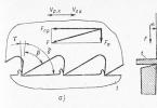
2 loads, uneven process flow, vibration and increased tool wear, increased loads on the machine. When machining with cylindrical cutters (cutting edges are located on a cylindrical surface), two processing methods are considered (Fig. 1.), depending on the direction of movement of the workpiece feed: counter milling, when the direction of movement of the cutting edge of the cutter in the process of cutting is opposite to the direction of movement of the feed; climb milling, when the direction of movement of the cutting edge of the milling cutter, which is in the process of cutting, coincides with the direction of movement of the feed. Rice. 1. Scheme of oncoming (a) and passing (b) milling. With counter milling, the load on the tooth increases from zero to the maximum, the forces acting on the workpiece tend to tear it off the table and raise the table. This increases the gaps in the AIDS system (machine tool, tool part), causes vibrations, deteriorates the quality of the processed surface. This method is well applicable for processing workpieces with a crust, cutting from under the crust, tearing it off, thereby greatly facilitating cutting. The disadvantage of this method is the large sliding of the blade over the previously processed and hardened surface. In the presence of some rounding of the cutting edge, it does not immediately enter the cutting process, but at first slips, causing a lot of friction and wear of the tool along the rear surface
3 nights. The smaller the thickness of the cut layer, the greater the relative amount of slippage, the greater part of the cutting power is spent on harmful friction. With passing milling, there is no such drawback, but the tooth begins to work from the greatest thickness of the cut layer, which causes large shock loads, but excludes the initial slippage of the tooth, reduces wear of the cutter and the surface roughness. The forces acting on the workpiece press it against the table, and the table against the bed guides, which reduces vibrations and increases machining accuracy. The tools for milling are cutters (from the French la frais strawberry), which are a multi-blade tool, the blades of which are located sequentially in the direction of the main cutting movement, designed for processing with a rotary main cutting movement without changing the radius of the trajectory of this movement and with at least one feed movement, the direction of which does not coincide with the axis of rotation. Cutters are: disc, cylindrical, conical in shape; by design, one-piece, composite, prefabricated and mounted, tail; according to the used material of the cutting edge, high-speed and carbide; by the location of the blades, peripheral, end and peripheral-end; right-handed and left-handed in the direction of rotation; in the shape of the cutting edge profile (shaped and rolling), spur, helical, with a helical tooth; by the shape of the posterior surface of the tooth, relief and non-relief, by purpose end, angular, slotted, keyway, shaped, threaded, modular, etc.
4 Let's consider the elements and geometry of the cutter on the example of a cylindrical cutter with helical teeth (Fig. 2.). Rice. 2. Elements of a cylindrical cutter with helical teeth. In fig. 2.The elements of a cylindrical cutter with helical teeth are shown: front surface 1, back surface 4, band 3 (0.05 0.1 mm wide), back surface (backed) 5, blade 2. The angle formed by the blade with the axis of the cutter is called the angle of inclination of the helical groove, or the angle of inclination of the spiral or the angle of inclination of the teeth and is denoted by ω. The clearance angle α (Fig. 2, b) is measured in a plane perpendicular to the axis of the cutter, that is, in the plane of its end face. Normal clearance angle αн is measured in a plane perpendicular to the blade. Rake angle γ is measured in a plane perpendicular to the blade. The transverse rake angle γ "is measured in a plane perpendicular to the cutter axis. The rake angle γ facilitates the formation and discharge of chips, the main clearance angle α helps to reduce the friction of the flank surface on the machined surface of the workpiece. For non-grooved teeth, the rake angle is within γ = 10 °. .30 o, clearance angle α = 10 o ... 15 o, depending on the material to be processed.At the recessed tooth, the posterior surface is made according to the Archimedes spiral, which ensures it the constancy of the section profile for all regrinds of the tool. and is performed, due to the complexity, only with a profile tool (shaped
5 and run-in), i.e. the shape of the cutting edge of which is determined by the shape of the machined surface. The rake angle of the undercut teeth is, as a rule, equal to zero, the rake angle has the values α = 8 o ... 12 o. The angle of inclination of the teeth ω provides a smoother entry of the blade into the cutting process compared to straight teeth and gives a certain direction to the chip flow. The face mill tooth has a more complex cutting blade. The cutting edge consists of the main, transition and auxiliary, having a main angle in the lead φ, an angle in the plan of the transition cutting edge φ p and an auxiliary angle in the lead φ 1. The geometrical parameters of the cutter are considered in a static coordinate system. Planning angles are angles in the basic plane P vc. The entering angle φ is the angle between the working plane P Sc and the cutting plane P nc The main angle in the entering is determined based on the cutting conditions as for a turning tool, at φ = 0 the cutting edge becomes only the butt edge, and at φ = 90 it becomes peripheral ... The auxiliary entering angle φ 1 is the angle between the working plane P Sc and the auxiliary cutting plane P "nc, it is 5 o ... 10 o, and the angle in the plan of the transition cutting edge is half of the main angle in the entering. The transition cutting blade increases strength The wear of cutters is determined, as in turning, by the amount of wear on the flank surface.For a high-speed cutter, the permissible width of the worn strip along the flank surface is 0.4 ... 0.6 mm for rough machining of steels, and 0.5 for cast irons. 0.8 mm, for semi-finishing steels 0.15 ... 0.25 mm, cast irons 0.2 ... 0.3 mm.For a carbide cutter, the permissible flank wear is 0.5 ... 0 , 8 mm. The durability of a cylindrical high-speed cutter is T = min, depending on the processing conditions, in some cases reaches 600 min, the durability of a carbide cutter is T = min. There are three types of milling, peripheral, end and peripheral end. processed on console milling machines (Fig. 3.) include:
6 horizontal planes; vertical planes; inclined planes and bevels; combined surfaces; ledges and rectangular grooves; shaped and corner grooves; dovetail grooves; closed and open keyways; keyways; shaped surfaces; spur gears by copying. Rice. 3. Scheme of surface treatment of workpieces on horizontal and vertical milling machines. Horizontal planes are machined with cylindrical (Fig. 3. a) on horizontal milling machines and end (Fig. 3. b) with milling cutters on vertical milling machines. Since the end mill has both
7, a larger number of teeth are blown in cutting, their processing is more preferable. Cylindrical milling cutters are used to machine, as a rule, planes up to 120 mm wide. Vertical planes are machined with end mills on horizontal machines and end mills on vertical ones (Fig. 3. c, d). Inclined planes are machined with end and end mills on vertical machines with a spindle axis rotation (Fig. 3.e, f), and on horizontal machines with corner cutters (Fig. 3.g). Combined surfaces are processed with a set of cutters on horizontal machines (Fig. 3. h). The ledges and rectangular grooves are machined with disk (on horizontal) and end (on vertical) cutters (Fig. 3. and, k), while the end mills allow high cutting speeds, since a larger number of teeth are simultaneously involved in the work. When machining grooves, disc cutters are preferable. Shaped and corner grooves are processed on horizontal machines with shaped, one and two-corner cutters (Fig. 3. l, m). Dovetail and T-shaped grooves are machined on vertical milling machines, as a rule, in two passes, first with an end mill (or on a horizontal milling machine with a disk cutter) a rectangular groove is processed along the width of the upper part. After that, the groove is finally processed with an end one-angle and special T-shaped (Fig. 3. n, o) milling cutter. Closed keyways are machined with end mills, and open keyways on vertical machines (Fig. 3. p, p). The keyways are machined on horizontal milling machines with disc cutters (Fig. 3.c). Shaped surfaces of an open contour with a curved generatrix and a rectilinear guide are machined on horizontal and vertical machines with shaped cutters (Fig. 3. t).
8 Face milling is the most widespread and productive way of machining flat surfaces of parts in conditions of serial and mass production. 2. END MILLING Basic types and geometry of face mills. In most cases, end mills with peripheral blades are used to machine open and recessed planes, i.e. working on the principle of peripheral end. The designs of end mills are standardized, the main types of which are given in table 1 / GOST, /. When processing planes with these cutters, the main work to remove the allowance is performed by the cutting edges located on the conical and cylindrical surfaces. The cutting edges located at the end, as it were, perform a surface cleaning, therefore, the roughness of the processed surface is less than when milling with cylindrical cutters. In the main plane P v, the entering angles are considered: the main entering angle, the minor entering angle 1 and the vertex angle ε. The entering angle is the angle between the cutting plane P n and the working plane P S. With a decrease in the entering angle at a constant feed per tooth and a constant depth of cut, the cut thickness decreases and the width increases, as a result of which the tool life increases. However, the operation of the cutter with a small angle in the plan (20 0) causes an increase in the radial and axial components of the cutting forces, which, with an insufficiently rigid AIDS system, leads to vibrations of the workpiece and the machine. Therefore, for end carbide mills with a rigid system and with a depth of cut t = mm, take the angle = At normal rigidity of the system =; usually take = Auxiliary lead angle 1 for face mills is taken equal The smaller this angle, the less the roughness of the machined surface.
9 In the main cutting plane P τ, the rake angle and the main clearance angle are considered. The rake angle is the angle between the main plane P v and the rake surface A γ, the main rake angle is the angle between the cutting plane P n and the main flank surface A α. Rake angle for solid carbide end mills = (+10 0) ... (20 0). Top clearance for solid carbide end mills = The angle of inclination of the main cutting edge is considered in the cutting plane. This is the angle between the cutting edge and the reference plane P v. It affects the strength of the tooth and the tool life of the cutter. For solid carbide end mills, the angle is recommended to be performed in the range from +5 0 to when machining steel and from 5 0 to when machining cast iron. The tilt angle of the helical teeth provides more even milling and reduces the instantaneous width of cut when plunging. This angle is selectable within the range End mill selection Select mill design. When choosing a cutter design (type), it is preferable to use prefabricated cutters with non-regrowth carbide inserts. The mechanical fastening of the inserts makes it possible to rotate them in order to update the cutting edge and allows the use of cutters without regrinding. After the plate is completely worn out, it is replaced with a new one. The manufacturer supplies each milling cutter with sets of replacement inserts. The entire set of plates can be replaced directly on the machine, while the time required for changing knives does not exceed minutes.
10 Choice of material of the cutting part. Mills for operation at low cutting speeds and low feeds are made of high-speed and alloy steels P18, KhG, KhV9, 9XS, KhVG, KhV5. Mills for processing heat-resistant and stainless alloys and steels are made from high-speed steels R9K5, R9K10, R18F2, R18K5F2, and when milling with impacts from steel grade R10K5F5. Grades of hard alloys are selected depending on the material being processed and the nature of the processing (Table 5). for finishing, a hard alloy with a lower cobalt content and a high carbide content (VK2, VK3 T15K6, etc.) is used, and for roughing with a high cobalt content, which gives a certain plasticity to the material and contributes to better performance under uneven and shock loads ( VK8, VK10, T5K10, etc.) Selection of the type and diameter of the cutter. Standard diameters of cutters (GOST, GOST, GOST, GOST, GOST, GOST, GOST, GOST, GOST) are given in tables 1 ... 4, their designations (for right-hand end mills) in tables 2, 3 and 4. Left-hand cutters are made according to the special order of the consumer. The types of end mills are selected according to the processing conditions from Table 1. The dimensions of the cutter are determined by the dimensions of the processed surface and the thickness of the cut layer. The diameter of the cutter, in order to reduce the main technological time and the consumption of tool material, is chosen taking into account the rigidity of the technological system, the cutting pattern, the shape and size of the workpiece being processed. For face milling, to achieve cutting conditions that provide the highest productivity, the cutter diameter D must be greater than the milling width B: D = (1.25 ... 1.5) B
11 Choice of geometric parameters Recommended values of the geometric parameters of the cutting part of end mills with carbide inserts are given in table 6/4 /, and from high-speed steel R18 in table. 7 / GOST, / The choice of a milling scheme The milling scheme is determined by the position of the axis of the end mill of the workpiece relative to the center line of the machined surface (Fig. 4.). A distinction is made between symmetrical and asymmetrical face milling. Rice. 4. Schemes of face milling. and with full symmetrical milling; b with incomplete symmetric milling; c, d with asymmetric milling
12 Symmetrical milling is called a milling in which the axis of the end mill passes through the center line of the machined surface (Fig. 4.a, b). Asymmetric milling is called a milling in which the axis of the end mill is displaced relative to the center line of the machined surface (Fig. 4.c, 4.d). Symmetrical face milling is divided into full, when the cutter diameter D is equal to the width of the machined surface B (Figure 4.a)., And incomplete, when D is greater than B (Figure 4.b). Asymmetric face milling can be up-and-down. The assignment of milling to these varieties is carried out by analogy with milling a plane with a cylindrical mill. With asymmetric counter-face milling, the thickness of the cut layer a changes from some small value (depending on the displacement value) to the largest a max = S z, and then decreases slightly. The displacement of the cutter tooth outside the machined surface from the side of the tooth starting cutting is usually taken within the range C 1 = (0.03 ... 0.05) D slice thickness close to maximum. The displacement of the cutter tooth outside the machined surface on the side of the tooth finishing cutting is assumed to be insignificant, close to zero) C 2 0. When machining cast iron blanks, in many cases, the cutter diameter is less than the width of the machined surface since cast iron blanks due to the fragility of cast iron, especially in the manufacture of body parts , are made of large dimensions. Face milling of cast iron blanks at B< D ф рекомендуется проводить при симметричном расположении фрезы. При торцовом фрезеровании стальных заготовок обязательным является их несимметричное расположение относительно фрезы, при этом: для заготовок из конструкционных углеродистых и легированных сталей и заготовок имеющих корку (черновое фрезерование) сдвиг заготовок в направле
13 cutting of the cutter tooth, which ensures the start of cutting with a small thickness of the cut layer; for workpieces made of heat-resistant and corrosion-resistant steels and during finishing milling, the workpiece is shifted towards the exit of the cutter tooth from cutting, which ensures the exit of the tooth from cutting with the minimum possible thickness of the cut layer. Failure to comply with these rules leads to a significant reduction in the tool life Purpose of the cutting mode The elements of the cutting mode during milling are (Fig. 5.): depth of cut; cutting speed; innings; milling width. Rice. 5 Elements of motion during cutting when milling with an end milling cutter.
14 1 direction of speed of the resulting cutting movement; 2 direction of speed of the main cutting movement; 3 working plane P s; 4 considered point of the cutting edge; 5 direction of the feed rate. The depth of cut t is defined as the distance between the points of the machined and machined surfaces located in the cutting plane and measured in the direction perpendicular to the direction of feed movement. In some cases, this value can be measured as the difference between the distances of the points of the machined and machined surfaces to the machine table or to some other constant base parallel to the direction of feed movement. The depth of cut is chosen depending on the machining allowance, power and rigidity of the machine. It is necessary to strive to conduct rough and semi-finishing milling in one pass, if the power of the machine allows it. Typically the depth of cut is mm. On powerful milling machines, when working with face mills, the depth of cut can be up to 25 mm. With a machining allowance of more than 6 mm and with increased requirements for the value of surface roughness, milling is carried out in two transitions: roughing and finishing. When finishing the transition, the depth of cut is taken within 0, mm. Regardless of the height of the roughness, the depth of cut cannot be less. The cutting edge has a certain radius of rounding, which increases with wear of the tool; at a small depth of cut, the material of the surface layer is crushed and subjected to plastic deformation. In this case, no cutting occurs. As a rule, with small machining allowances and the need for finishing (roughness value R a = 2 0.4 μm), the depth of cut is taken within 1 mm. At a shallow depth of cut, it is advisable to use cutters with round plates (GOST, GOST). At a depth of cut greater than 3 ... 4 mm, cutters with six, five and tetrahedral plates are used (Table 2).
15 When choosing the number of transitions, it is necessary to take into account the requirements for the roughness of the machined surface: rough milling R a = 12.5 ... 6.3 μm (3 ... 4 class); finishing milling R a = 3.2 ... 1.6 microns (5 ... 6 class); fine milling R a = 0.8 ... 0.4 μm (7 ... 8 class). To ensure finishing, it is necessary to carry out roughing and finishing transitions, the number of working strokes during roughing is determined by the size of the allowance and the power of the machine. The number of strokes during finishing is determined by the requirement for surface roughness. In production conditions, when roughing and finishing are required, they are divided into two separate operations. This is due to the following considerations. Roughing and finishing are carried out using different materials of the cutting part of the cutter and at different cutting speeds, which would cause an unreasonably long time for changeover of the machine, if these transitions were performed in one operation. Roughing leads to high vibrations and uneven and alternating loads, which, in turn, leads to rapid machine wear and loss of machining accuracy. Roughing leads to the formation of a large amount of chips, as well as abrasive dust, which requires special measures for waste disposal. Typically, roughing machines are separate from finishing and finishing machines. The milling feed is the ratio of the distance traveled by the considered point of the workpiece in the direction of feed movement to the number of revolutions of the cutter or to the part of the cutter revolution corresponding to the angular pitch of the teeth. Thus, when milling, the feed per revolution S o (mm / rev) is considered, the movement of the considered point of the workpiece in a time corresponding to one revolution of the cutter, and the feed per tooth S z (mm / tooth)
16 viewed point of the workpiece in the time corresponding to the rotation of the cutter by one angular pitch of the teeth. In addition, the feed rate v s is also considered (previously it was defined as a minute feed both in the old literature and on some machines this term is still used), measured in mm / min. The feed rate is the distance traveled by a given point of the workpiece along the trajectory of that point in the feed movement per minute. This value is used on machines for setting up the required mode, since in milling machines, the feed movement and the main cutting movement are not kinematically interconnected. Applying the ratio of feed and cut speeds helps to correctly determine the S o and S z values. Using the dependencies: S o = S z z, v s = S o n where z is the number of teeth of the cutter, n is the number of revolutions of the cutter (rpm), we define v s = S o n = S z z n. The initial value for rough milling is the feed per tooth S z, as it determines the tooth stiffness of the cutter. The roughing feed is selected as high as possible. Its value can be limited by the strength of the machine feed mechanism, the strength of the cutter tooth, the rigidity of the AIDS system, the strength and rigidity of the mandrel, and for other reasons. In finishing milling, the feed per revolution of the cutter S o is decisive, which affects the value of the roughness of the machined surface. Recommended feed rates for various cutting conditions are shown in tables 8, 9, 10. Milling width B (mm) The surface area measured in a direction parallel to the milling cutter axis in peripheral milling and perpendicular to the direction of feed movement in face milling. The milling width is determined by the smallest of two values: the width of the workpiece to be machined and the length or diameter of the cutter. The cutting speed for milling, v, is defined as the linear speed of the cutter point (m / min). The actual cutting speed is determined by the formula D n m v, () 1000 min
17 where D is the diameter of the cutter (mm) at the point of the cutting edge farthest from the axis of rotation, n is the number of revolutions of the cutter (mm / rev). the formula is the following Allowable (calculated) cutting speed is determined by the empirical v T where Cv coefficient characterizing the material of the workpiece and cutter; T tool life (min); t cutting depth (mm); S z feed per tooth (mm / tooth); B milling width (mm); Z is the number of teeth of the cutter; D q, m, x, y, u, p exponents; m t (m / min) k v general correction factor for changed processing conditions. The values C v q, m, x, y, u, p are given in Table 11. x C v S y z q B u z Average values of the tool life of face mills with a cutter diameter p k v Table Cutter diameter (mm) Tool life (min) Total correction factor K v. Any empirical formula is determined with the constancy of certain factors. In this case, these factors are the physical and mechanical properties of the workpiece and the material of the cutting part of the tool, the geometric parameters of the tool, etc. In each specific case, these parameters change. To take these changes into account, a general correction factor K v is introduced, which is the product
18 separate correction factors, each of which reflects the change, relative to the initial, individual parameters / 5 /: K v = K v K pv K and v K v, K v coefficient taking into account the physical and mechanical properties of the processed material, tables 12, 13; K pv coefficient, taking into account the state of the surface layer of the workpiece, table 14; K and v coefficient, taking into account the tool material, table 15; K v coefficient that takes into account the value of the main angle in the entering, Table K v 1.6 1.25 1.1 1.0 0.93 0.87 Knowing the permissible (design) cutting speed v, determine the design speed of the cutter 1000v n D where n the number of revolutions of the cutter, min 1; D cutter diameter, mm. According to the passport of the machine, a speed level is chosen at which the number of revolutions of the cutter will be equal to the calculated one or less than it, i.e. n f n, where n f is the actual number of revolutions of the cutter, which must be installed on the machine. It is allowed to use such a speed step at which the increase in the actual number of revolutions in relation to the calculated one will be no more than 5%. According to the selected number of revolutions of the machine spindle, the actual cutting speed D nph m vf, () 1000 min is specified and the feed rate (minute feed) is determined:
19 v S (S m) = S zzn f = S about n f (mm / min.) Then, according to the machine passport, the most suitable value is chosen that is closest to or equal to the calculated value Checking the selected cutting mode The selected cutting mode is checked by using the power on the machine spindle and the force required to effect the feed movement. The power spent on cutting must be less than or equal to the power on the spindle: N p N shp, where N p is the effective cutting power, kW; N shp is the permissible power on the spindle, determined by the drive power, kW. The drive of the machine is a set of mechanisms from the source of motion to the working body. The drive of the main cutting movement is a set of mechanisms from the electric motor to the spindle of the machine, and its power is determined based on the power of the electric motor and losses in the mechanisms. The power on the spindle is determined by the formula N shp = N e, where N e is the power of the electric motor of the drive of the main cutting movement, kW, the efficiency of the machine drive mechanisms, = 0.7 ... 0.8. The cutting power during milling is determined by the formula N M cr n, (kW) where M cr is the torque on the spindle, Nm, n is the number of revolutions of the cutter, min 1. The torque on the spindle of the machine is determined by the formula: M cr P z D, (Nm)
20 cutters, mm. formula 2 where P z is the main component (tangent) of the cutting force, N; D diameter The main component of the cutting force P z during milling is determined by x y u C p t S B z Pz 10 K q w p D n where C p is the coefficient characterizing the material being processed and other conditions; K p is the general correction factor, which is the product of coefficients reflecting the state of individual parameters affecting the magnitude of the cutting force, K p = K p K vp K p K v, K p coefficient that takes into account the properties of the material of the workpiece being processed (Table 17); Table 16. K vр coefficient taking into account the cutting speed (table 18); K p coefficient taking into account the value of the front angle (table 19); K p is a coefficient that takes into account the value of the angle in the plan (Table 19). The values of the coefficient C p and the exponents of the degrees x, y, u, q, w are given in. The magnitude of the radial component of the cutting force P y can be determined by the ratio P y 0.4 P z. If the condition N p N shp is not met, then it is necessary to reduce the cutting speed or change other cutting parameters. When milling, it is of great importance to represent the cutting force along the vertical P in and horizontal P g components. The horizontal component of the cutting force P g is the force that must be applied to ensure the feed movement, it must be less (or equal) to the maximum force allowed by the longitudinal feed mechanism of the machine: P g P add, N.
21 where P extra is the greatest effort allowed by the longitudinal feed mechanism of the machine (N) is taken from the passport data of the machine (Table 20). The horizontal component of the cutting force is determined from the following ratios and depends on the type of face milling / 5 /: with symmetric milling P g = (0.3 ... 0.4) P z; with an asymmetric opposite P g = (0.6 ... 0.8) P z; with asymmetric passing P g = (0.2 ... 0.3) P z; If the condition P g P add is not met, it is necessary to reduce the cutting force P z by reducing the feed per tooth S z and, accordingly, the feed rate v S (minute feed S m) Calculation of the operation time and equipment use Piece time T pcs time , spent on the operation, is determined as the time interval equal to the ratio of the cycle of the technological operation to the number of simultaneously manufactured products and is calculated as the sum of the components T pc = T o + T vp + T obs + T dep, (min) where T o is the main time, this is a part of the piece time spent on changing and then determining the state of the object of labor, i.e. the time of the direct impact of the tool on the workpiece; T in auxiliary time, this is the part of the piece time spent on performing the techniques necessary to ensure a direct impact on the workpiece. T obs is the time of servicing the workplace, this is a part of the piece time spent by the performer on maintaining the technological equipment in working condition and caring for them and the workplace. The maintenance time of the workplace consists of the time of organizational maintenance (inspection and testing of the machine, laying out and cleaning of the tool, lubrication and cleaning
22 machines) and maintenance time (adjustment and readjustment of the machine, change and readjustment of cutting tools, dressing of grinding wheels, etc.); T ot the time for personal needs, this is part of the piece time spent by a person on personal needs and, with tedious work, on additional rest; Main time The main time in milling is equal to the ratio of the length of the path traveled by the cutter for the number of working strokes to the feed rate, and is determined by the formula T o L iv S (ll) 1 l2 iv (min) where L is the total length of the cutter pass in the feed direction , mm; i number of working strokes; l the length of the workpiece to be processed, mm; l 1 value of the cutter penetration, mm; l 2 the value of the cutter overrun, mm; l 2 = mm. The amount of penetration l 1 when milling with end mills is determined from the conditions: with symmetrical incomplete (for the case in Fig. 2a): 2 2 l1 0.5 (D D B); with an asymmetric opposite (for the case in Fig. 2b): l1 0.5 D C1 (D C1); with an asymmetric passing (for the case in Fig. 2c): l 1 = 0.5 D, where D is the cutter diameter, mm; B workpiece width, mm; C 1 is the displacement of the cutter relative to the end of the workpiece (Fig. 2b). S
23 .6.2 Auxiliary time. 2 This time includes the time spent on setting, fixing, removing the workpiece (Table 21), the time to control the machine while preparing the working stroke (Table 22), making measurements during processing (Table 23) Operational time. The sum of the main and auxiliary time is called the operational time: T op = T o + T ex. Operational time is the main component of unit time Time for servicing the workplace and time for personal needs Time for servicing the workplace and time for personal needs is often taken as a percentage of the operational time: T obs = (3 ... 8%) T op; T dep = (4 ... 9%) T op; T obs + T dep 10% T op Piecewise calculation time To determine the standard time for performing a certain amount of work in specific production conditions by one or more workers, it is necessary to determine the piece calculation time T shk, which includes, in addition to the piece time, also the time for preparation of workers and means of production for performing a technological operation and bringing them to their original state after its completion, preparatory and final time T pz. This time is needed to receive the task, devices, equipment, tools, install them, to set up the machine to perform an operation, remove all equipment and hand them over (Table 24). In the piece costing time, the preparatory final time is included as a proportion of it attributable to one workpiece. The more workpieces n are processed
24 from one setup of the machine (from one setup, in one operation), the less part of the preparatory and final time is included in the piece calculation. T pz T shk T pc n In mass production, T pz is assumed to be zero, since almost all work is performed with one machine setup. Calculation of the need for equipment. The estimated number of machines (Z) for performing a certain operation is calculated by the formula T pcs P z, T cm 60 where T pcs is the piece time, min; P program for making parts per shift, pcs; T cm is the operating time of the machine per shift, h. In the calculations, the operating time of the machine per shift is taken to be T cm = 8 hours, in real conditions at each enterprise this time can be taken differently. Technical and economic efficiency. The assessment of the technical and economic efficiency of the technological operation is carried out according to a number of coefficients, including: the coefficient of the main time and the coefficient of utilization of the machine in terms of power / 7, 8, 9 /. The coefficient of the main time K o determines its share in the total time spent on the operation K o T T pc where Ko is the coefficient of the main time / 9 /. O
25 The higher K о, the better the technological process is built, since the more time allotted for the operation, the machine works, and does not stand idle, i.e. in this case, the share of auxiliary time is reduced. Roughly the value of the coefficient K about for different machines is in the following limits broaching machines K about = 0.35 ... 0.945; continuous milling K o = 0.85 ... 0.90; the rest K about = 0.35 ... 0.90. If the coefficient of the main time Kо is lower than these values, then it is necessary to develop measures to reduce the auxiliary time (the use of high-speed devices, automation of part measurements, the combination of the main and auxiliary times, etc.). The utilization factor of the machine by power K N is defined as K N N N st P de K N the utilization factor of the machine by power / 9 /; N P cutting power, kW (in the calculation, take that part of the technological operation that occurs with the greatest consumption of cutting power); N article power of the main drive of the machine, kW; Efficiency of the machine. The closer K N is to 1, the more fully the power of the machine is used. If the machine is not fully loaded, the energy use rate deteriorates. The total electrical power consumed from the network, S, is divided into active P and reactive Q. Their ratios are defined as P P P Scos; S; cos cos S When the motor is fully loaded, the cosφ value will not be equal to 1, i.e. in this case, reactive energy is also consumed from the network. Taking into account the motors used, the approximate cosφ values will be as follows:
26 at 100% load cosφ = 0.85, at 50% load 0.7, at 20% load 0.5, and at idle speed 0.2 of this value. Consider an example of the correct use of a number of milling machines (models 6P13, 6H13, 6P12, 6H12, 6P11), if the power required for cutting is N rez = 3.2 kW. Indicators Models of milling machines 6P13 6N13 6P12 6N12 6P11 Power el. engine N ed 11.0 10.0 7.5 7.0 5.5 Idle power N xx 2,200 2,500 2,250 1,750 1,100 Cutting power N cut 3,200 3,200 3,200 3,200 3,200 Active power P = N xx + N cut 5.400 5.700 5.450 4.950 4.300 Utilization factor KN 0.491 0.570 0.727 0.707 0.782 power of the electric motor Cosine phi cos φ 0.585 0.635 0.718 0.708 0.740 Total power consumption S 9.231 8.976 7.591 6.992 5.811 Efficiency factor K eff 0.585 0.635 0.718 0.708 0.740 consumed electric power Overused N out of 3.831 3.276 2.141 2.042 1.511 power from the mains Unjustified expenditure of electrical power N neop 2.320 1.766 0.630 0.531 0.000 From the given example it can be seen that the wrong choice of the machine leads to such overspending of electricity, which can be compared with the cutting power.
27 In order to repay the overused reactive power, for which enterprises pay significant fines, it is necessary to create special devices to repay it with capacitive power. 3. EXAMPLE OF CALCULATION OF THE CUTTING MODE 3.1. Problem conditions Initial data. The initial data for calculating the cutting mode are: workpiece material forging from steel 20X; the ultimate strength of the workpiece material в = 800 MPa (80 kg / mm 2); width of the processed surface of the workpiece, B 100 mm; length of the processed surface of the workpiece, L 800 mm; required roughness of the treated surface, R a 0.8 μm (roughness class 7); total machining allowance, h 6 mm; average daily production program for this operation, P 200 pcs Purpose of calculations. As a result of the calculations, it is necessary to: select a cutter by elements and geometric parameters; choose a milling machine; calculate the values of the elements of the cutting mode, cutting depth t, feed S, cutting speed v; check the selected cutting mode according to the drive power and the strength of the machine feed mechanism; calculate the time required to complete the operation; calculate the required number of machines; check the effectiveness of the selected cutting mode and equipment selection.
28 3.2. Calculation procedure Choice of cutting tools and equipment. Based on the total machining allowance h = 6 mm and the requirements for surface roughness, we perform milling in two steps: roughing and finishing. According to table 1, we determine the type of milling cutter, we select an end mill with multifaceted carbide inserts according to GOST. 2, 3, 4 GOST, diameter D = 125 mm, number of teeth z = 12, pentahedral plates, conventional designation We select the material of the cutting part of the cutter according to table 5 for rough milling of carbon and alloy unhardened steel T5K10, for finishing milling T15K6. The geometrical parameters of the cutter are selected according to tables 6 and 7 for cutters with carbide inserts (table 6) when processing structural carbon steel with σв 800 MPa and feed for rough milling> 0.25 mm / tooth: = 5 0; = 8 0; = 45 0; o = 22.5 0; 1 = 5 0; = 14 0; for fine feed milling< 0,25 мм/зуб: = 5 0 ; = 15 0 ; = 60 0 ; о = 30 0 ; 1 = 5 0 ; = Черновое фрезерование производим по схеме несимметричное встречное (Рис. 4), чистовое несимметричное попутное (Рис. 4). Предварительно принимаем проведение работ на вертикально фрезерном станке 6Р13, паспортные данные в таблице Расчёт элементов режима резания Назначение глубины резания. При назначении глубины резания в первую очередь из общего припуска выделяется та его часть, которая остаётся для проведения чистовой обработки t 2
29 = 1 mm. Finishing milling is carried out in 1 working stroke i 2 = 1. Hence, the allowance h 1 for rough milling will be: h 1 = 6 1 = 5 mm. To remove this allowance, one working stroke is enough, therefore, we take the number of working strokes for rough milling i 1 = 1. Then the depth of cut t 1 for rough milling will be t 1 = h 1 / i 1 = 5/1 = 5 mm Purpose of the feed. The feed for rough milling is selected from tables 8 and 9. For face mills with carbide inserts (table 8) with a machine power> 10 kW with asymmetric counter milling for a T5K10 plate, the feed per tooth is within S z1 = 0.32 0 , 40 mm / t. We accept a smaller value for guaranteed provision of the power condition on the spindle S z1 = 0.32 mm / tooth, the feed per revolution will be. S о1 = S z1 z = 0.32 12 = 3.84 mm / rev. The feed rate for finishing milling is selected according to Table 10. For end mills with carbide inserts (part B) with material having σ in 700 MPa with a roughness of the machined surface R a = 0.8 μm with an angle of 1 = 5 0 feed per revolution of the cutter is in the range S о2 = 0.30 0.20 mm / rev. We take a large value to increase the productivity of the process S о2 = 0.30 mm / rev. In this case, the feed will not be a tooth S z2 = S о2 / z = 0.30 / 12 = 0.025 mm / tooth Determination of the cutting speed. The cutting speed is determined by the formula: v T mt The values of the coefficient C v and exponents are determined according to table 11. For rough and finish milling of structural carbon steel with σ in 750 MPa using carbide inserts: x C v = 332, q = 0.2 ; m = 0.2; x = 0.1; y = 0.4; u = 0.2; p = 0.C v S D y z q B u z P K v
30 We take T = 180 min, clause 2.4 table 1. The general correction factor Kv = K v K pv K and v K v Kv are found from table 12 for steel processing. Calculation formula K v = K g (750 / in) nv. According to table 13, we find for the processing of carbon steel with σ> 550 MPa for the material of the hard alloy tool K g = 1, n v = 1. Then K v1.2 = 1 (750/800) 1.0 = 0.938. K v is found from the table for rough milling at = 45 about K v1 = 1.1; for finishing milling at = 60 о K v2 = 1.0. We find K pv according to table 14 for machining during rough milling of the forging K pv1 = 0.8, for finishing milling without a crust K pv2 = 1. K and v are found from table 15 for machining steel with a structural mill with T5K10 carbide inserts for rough milling K and v1 = 0.65, with T15K6 carbide inserts for finishing milling K and v2 = 1. The general correction factor for rough milling is K v1 = 0.938 1.1 0.8 0.65 = 0.535. The general correction factor for rough milling is K v2 = 0.938 1.0 1.0 1.0 = 0.938. The cutting speed for rough milling is v, 2 5 0.32 0.4 0.626 0.535 0.535 2.8251.1750.634 2.832 0.535 88.24 m / min 5.286 The cutting speed for finishing milling is: 0 v, 2 1 0.025 0, 4 0.832 0.25 m / min 1.625 The calculated speed of the cutter is determined for rough and finish milling by the expression 0.626 0.938 0.938 2.8251 0.229 2.5121
31 n, 24 3, vn D 224.82 rpm rpm n 2 (min 1), 25 3.16 rpm Clarification of cutting conditions According to the passport of the 6P13 machine, we clarify the possible setting of the cutter speed and find the actual values for the roughing machining n ph1 = 200 min 1, for finishing n ph2 = 1050 min 1, i.e. we choose the nearest smallest values from the calculated ones. As a result of this, the actual cutting speed will also change, which during roughing will be v ф1 = πdn / 1000 = 3, / 1000 = 78.50 m / min, and during finishing v ф2 = πdn / 1000 = 3, / 1000 = 412 , 12 m / min. To clarify the feed rates, it is necessary to calculate the feed rate v S by the feed per tooth and per revolution v S = S o n = S z z n; v S1 = 0, = 768 mm / min; v S2 = 0, = 315 mm / min. According to the machine passport, we find a possible setting for the feed rate, choosing the nearest smallest values, v S1 = 800 mm / min, since this value is only 4.17% higher than the calculated one and v S2 = 315 mm / min. Based on the accepted values, we clarify the values of feeds per tooth and per revolution S oph1 = 800/200 = 4 mm / rev; Soff2 = 315/1050 = 0.3 mm / rev; S zf1 = 4/12 = 0.333 mm / tooth; S zf2 = 0.3 / 12 = 0.025 mm / tooth; Checking the selected cutting mode The selected cutting mode is checked according to the characteristics of the machine: the power on the machine spindle and the maximum allowable force applied to the feed mechanism. Since the loads on the machine during roughing are much higher than during finishing, we check the selected cutting mode for rough milling.
32 The power spent on cutting must be less than or equal to the power on the spindle: N p N shp. Power on the spindle N shp = N e = 11 0.8 = 8.8 kW. The cutting power during rough milling is determined by the formula M cr1 nph 1 Pz1 vph 1 N p Torque is determined by the formula (kW) Df Mkr1 Pz 1 (Nm) The main component of the cutting force is determined by the formula P z1 10C ptx 1 q DS n The value of the coefficient Ср and exponents x, y, u, q, w are found from Table 16: Cp = 825; x = 1.0; y = 0.75; u = 1.1; q = 1.3; w = 0.2. When the cutter is blunt to the permissible value, the cutting force increases in steel with σ> 600 MPa by 1.3 to 1.4 times. We accept an increase of 1.3 times. General correction factor K р = K р K vр K р K р. K p is determined according to table 17 for processing structural carbon and alloy steels K p = (w / 750) np, exponent n p = 0.3, then K p = (800/750) 0.3 = 1.02. K vр is determined according to table 18 for roughing at a cutting speed up to 100 m / min with negative values of the rake angle K vр1 = 1, for finishing at a cutting speed up to 600 m / min K vр2 = 0.71. K p and K p are determined according to table 19. At = 5 о K р = 1.20 and at = 45 о K р1 = 1.06, at = 60 о K р2 = 1.0. The value of the general correction factor will be K p1 = 1.02 1 1.20 1.06 = 1.297; К р2 = 1.02 0.71 1.20 1.0 = 0.869 The main component of the cutting force during rough milling will be y f1 w f1 B uz K p (N) P z 1 1 0.75 1.439158.4912 1, 3 1.297 1.686 1.3 0.09 2.45 1.7 (H) 1535.08
33 The torque will be determined as 37826.7 125 M cr, 17 (Nm) Cutting power during rough milling will be defined as The condition for the correct selection of the cutting mode according to the drive power N p N shp is not observed, since 48.51 8.8, this means that the selected cutting mode cannot be carried out on this machine. Reducing the cutting power is most effective by reducing the cutting speed, as well as reducing the feed per tooth. The cutting power must be reduced by 5.5 times; for this, the cutting speed will be reduced by reducing the speed of the cutter from 200 to 40 rpm from 78.5 m / min to 14.26 m / min. In this case, the feed rate will decrease from 768 mm / min to v S1 = 0, = 153.6 mm / min. Since a change in the depth of cut will lead to the need for a second working stroke, we will change the value of the feed rate to 125 mm / min (Table 20), while the feed per cutter tooth will be S z1 = 125/12 40 = 0.26 mm / tooth. 2364, Substituting the new value of the feed per tooth in the formula for calculating the main component of the cutting force, we obtain P z1 = 31405.6 N, the torque will be equal to M cr1 = 1960.3 Nm, the cutting power N p1 = 8.04 kW, which meets the requirements for drive power. The second condition is that the horizontal component of the cutting force (feed force) must be less (or equal) to the maximum force allowed by the longitudinal feed mechanism of the machine: P g P add. For the 6P13 machine, P add = N. The horizontal component of the cutting force Pg under the condition of asymmetric oncoming rough milling 37826.7 78, N p 1 P g = 0.6 P z1 = 0.3 = 18818.58 N. 48.51 (kW ) Since the condition P g P add is not met (18818,), the selected cutting mode does not satisfy the condition of the strength of the longitudinal mechanism
34 dachas of the machine. To reduce the horizontal component of the cutting force, it is necessary to reduce the feed per cutter tooth. Let us represent the formula for calculating the main component of the cutting force in the form P 1 0.75 1, Sz, 75 1.3 1.6 S 1.3 0.2 z z1 N P add / 0, / 0, N. From this condition we find S z S 0.75 z 1 0.192 mm / zu b 86165.6 By the newly selected value of S z1, we determine v s1 = 0, = 92.16 mm / min, the nearest lower value on the machine is v s1 = 80 mm / min. The actual feed per revolution of the cutter will be S oph = 2 mm / rev, the actual feed per tooth of the cutter will be S zf = 0.167 mm / tooth. Due to the multiple excess of the indicators of the first calculation over the permissible ones, it is necessary to check the correctness of the choice of the cutting mode during the finishing transition. P z 2 1 0.75 1.4912 1.3 0.869 1.1297 1.3 0.09 4.08 1.0 (N) 2139.0 The main component of the cutting force during finishing is significantly lower than the permissible values, due to than adjusting the calculation is not required. () The final calculation data are summarized in the table Name of indicators Units of measure For the transition to roughing Depth of cut t mm 5 1 finishing Estimated feed per cutter tooth S z mm / tooth 0.323 0.025 Estimated feed per cutter revolution S o mm / rev 3.84 0 , 3 Design cutting speed v m / min 88.24 503.25
35 Calculated cutter speed n rpm 224.16 Actual cutter speed n f rpm Actual cutting speed v f m / min 78.50 412.12 Calculated feed speed v S mm / min Actual feed speed v Sph mm / min Actual feed per cutter revolution S oph mm / rev 4 0.3 Actual feed per cutter tooth S zf mm / tooth 0.333 0.025 Main component of cutting force P z N 37826.7 521 Torque M cr Nm 2364.17 Cutting power N kW 48.51 The first correction of the cutting mode Actual number of revolutions of the cutter n f rpm 40 Actual cutting speed v f m / min 15.7 Calculated feed rate v S mm / min 159.84 Actual speed of the feed v Sph mm / min 160 Main component of the cutting force P z N 31364.3 Torque M cr Nm 1960.3 Cutting power N kW 8.08 Horizontal comp. cutting forces P g N 18818.5 Second correction of the cutting mode Calculated feed per cutter tooth S z mm / tooth 0.192 Calculated feed rate v S mm / min 92.16 Actual feed rate v Sph mm / min 80 Actual feed per revolution S of mm / rev 2 Actual feed per tooth S zf mm / tooth 0.167 8 Thus, the machine is adjusted according to the following values: Rough transition n ф1 = 40 min 1, v S1 = 80 mm / min; Finishing transition n ф2 = 1050 min 1, v S2 = 315 mm / min.
Practical work 3 Calculation of the norm of time for milling work Purpose of work Consolidation of theoretical knowledge, the acquisition of skills in standardization of a milling operation for a given part in various organizational and technical
Topic 7. PROCESSING OF BLANKS BY MILLING Purpose - to study the technological possibilities of shaping surfaces by milling, the main units of milling machines and their purpose, tools for
MINISTRY OF AGRICULTURE OF THE RUSSIAN FEDERATION RUSSIAN STATE AGRARIAN UNIVERSITY RGAU Moscow Agricultural Academy named after K.A. TIMIRYAZEVA Faculty Technical service in the agro-industrial complex Department of Materials Science and Technology
MINISTRY OF AGRICULTURE OF THE RUSSIAN FEDERATION Moscow State Agroengineering University named after V.P. Goryachkina UDC 63 Reviewer: Candidate of Technical Sciences, Associate Professor of the Department of Repair and Reliability
MINISTRY OF AGRICULTURE OF THE RUSSIAN FEDERATION RUSSIAN STATE AGRARIAN UNIVERSITY RGAU Moscow Agricultural Academy named after K.A. TIMIRYAZEVA Faculty "Technical service in the agro-industrial complex" Department "Materials science and technology
Practical work 2 Calculation of the norm of time for drilling work Purpose of work Consolidation of theoretical knowledge, the acquisition of skills for standardizing the drilling operation for a given part in various organizational and technical
ELEMENTS OF THE CUTTING MODE Elements of the cutting mode when turning The essence of turning is the formation of a cylindrical surface with a tool with one cutting edge, while, as a rule,
Practical work 5 Calculation of the norm of time for grinding work Purpose of work Consolidation of theoretical knowledge, the acquisition of skills in standardization of grinding operations for a given part in various organizational and technical
LABORATORY WORK 6 PROCESSING ON MILLING MACHINES Purpose of the work: to familiarize students with the basics of the milling process, the device of a milling machine, cutting tools and devices. Choice
4 TURNING PROCESS Turning is the simplest and most illustrative process, on the basis of which more complex types of machining are further studied. Cutting tool turning tool represents
What is a countersink? Countersinks are axial multi-edge cutting tools that are used for intermediate or final machining of holes obtained by pre-drilling, casting, forging.
End Mill Geometry Backcut Size Belt Width Helical Groove Angle Auxiliary Cutting Edge Core Diameter Nape Drop Amount Back Surface Main
Practical work 4 Calculation of the norm of time for gear cutting work Purpose of work Consolidation of theoretical knowledge, the acquisition of skills in standardizing gear hobbing and gear shaping operations for a given part
Being the best through innovation OUT 1 Geometry and design of end mills Total length Cutting length Flat (Weldon shank) Thread (threaded shank) Milling cutter diameter Shank diameter Angle
6.2. Grinding Grinding is the process of machining workpieces of machine parts by cutting with the help of abrasive wheels. The abrasive grains are randomly arranged in the grinding wheel and held together by the bonding material.
Table of contents Determination of forces acting during turning and power ... 3 Calculation of cutting conditions during turning by analytical method ... 5 Calculation of parameters of cutting conditions during turning
CONTENT OF THE WORKING PROGRAM OF THE TRAINING DISCIPLINE. OP.05 "General fundamentals of metalworking technology and work on metal-cutting machines" Names of sections and topics Topic 1. Physical foundations of the cutting process
Leс_15_TKMiM_1АА_AD_LNA_08_12_2016 Contents 15.1. Incisors 15.2. Hole machining tools 15.3. Cutters Test questions Tasks for independent work References By appointment (or
Countersinks Countersink is a multi-edge cutting tool designed for preliminary or final machining of drilled, stamped or cast holes Main features and differences of countersinks
A. KINEMATICS OF THE CUTTING PROCESS AND SECTION OF THE CUT WHEN WORKING WITH THE BLADE TOOL used the notation given
Reznikov L.A. Cutting materials: Collection of tasks. Togliatti: TSU, 006. DEFORMATIONS AND FORCES WHEN CUTTING WITH BLADE TOOLS.
CHECK TASK 2.1 Selection of tool materials for various types of processing and geometric parameters of cutters during turning. Task 1. Select the material of the cutting part of the tools
FEDERAL AGENCY FOR EDUCATION Bryansk State Technical University Approved by the Rector of the University A.V. Lagerev 2006 TECHNOLOGICAL PROCESSES OF MACHINE PRODUCTION TECHNOLOGY
PRIMARY PROFESSIONAL EDUCATION L.I.VEREINA Performing work in the profession of "MILLING MILLER"
5.3. Drilling Drilling is a common method of making holes in solid material. Through and blind (blind) holes are obtained by drilling and the previously obtained holes are processed
TECHNICAL MANUAL - Monolithic milling cutters General information Actual diameter of ball milling cutters Problem solving T2 T8 T10 Grade selection of solid cutter Work material Hardened steels
UDC 621.9.022.2 SELECTION OF THE CUTTING MODE WHEN MILLING PLANES WITH END MILLS EQUIPPED WITH CARBIDE INSERTS VA SAMSON, BD DANILENKO [email protected] Brief recommendations provided
Characteristics of the blade Lecture 2 1. Coordinate planes. Coordinate systems Coordinate planes. When designing, manufacturing and operating the blades of cutting tools, they are considered in a rectangular
1 Initial data When calculating a combined drill, the initial data are: the diameters of the steps of the hole being machined d 1 and d 2, respectively, the lengths of the steps of the hole being machined l 1 and l
CYLINDRICAL MILLS TECHNICAL SPECIFICATIONS GOST 29092-91 CYLINDRICAL MILLS Specifications Cylindrical milling cutters. Specifications GOST 29092 91 OKP 39 1832 Date of introduction 01.01.93 This standard
Choice of cutting data for beginners and more. Posted on the website http://et-rus.ru/ The situation is typical: we are sure that the expensive tool we bought will do the job for us. the whole instrument is worth
Lec_12_TKMiM_1АА_АД_LNA_20_10_2016 Introduction Contents 12.1. Cutting types 12.2. Blanks 12.3. Types of movements in metal-cutting machines 12.4. Surfaces and planes in turning 12.5.
Progressive woodworking equipment and tools Glebov I.T. (UGLTU, Yekaterinburg, RF) [email protected] SELECTION OF SOCKETS UNDER THE SPIKE WITH THE WORKING OF MORTISE HOLE THE GROOING
Geometry of the working part of turning tools Purpose of the work: consolidation of theoretical knowledge about the purpose, application and design of general-purpose turning tools; familiarization with methods and means of measurement
UDC 621.919.1.04 + 621.9.01 MATHEMATICAL MODEL OF THE CUTTING AREA FOR MULTI-COORDINATE MILLING V.A. Batuev, V.V. Batuev Based on analytical geometry in space, a mathematical model has been developed
SECONDARY VOCATIONAL EDUCATION A. M. ADASKIN, N. V. KOLESOV MODERN CUTTING TOOL Recommended by the Federal State Institution "Federal Institute for the Development of Education" as
Practical work 1 Calculation of the norm of time for turning work 1 Purpose of work Consolidation of theoretical knowledge, the acquisition of skills in standardization of a turning operation for a given part in various organizational and technical
Technical and commercial proposal for tools and accessories to a sharpening machine for wood-cutting tools model VZ-384 1. Price, conditions and delivery time. The prices for the fixtures are indicated in the price list.
Ministry of Education of the Russian Federation Saratov State Technical University Technological Institute STUDY OF THE CONSTRUCTION OF MILLS Methodical instructions for laboratory work on the course
Steel working techniques Wear-resistant sheet steel and high-strength structural steel are steel grades that can be machined with high-speed
Research in the field of technological quality assurance when processing the surfaces of parts on vertical milling machines. Part 2. Investigation of schemes for processing various surfaces of parts with end
Technology of processing shaped surfaces (for example, turbine blades) Saminskaya Galina Grigorievna, teacher of technical special disciplines PU-43, St. Petersburg Turbine blades are
Grinding machine VZ-384 Purpose: intended for sharpening and finishing the main types of tools made of tool steel, hard alloy, mineral ceramics with abrasive, diamond, CBN
Laboratory work 1 Determination of the rigidity of the technological system when processing parts by the method of forward and reverse feeds 1. Purpose of the work The work provides for familiarization with the method of determining the rigidity
QUESTIONS WHICH WERE ASKED ON THE PROTECTION OF DIPLOMA PROJECTS ON REPAIR OF EQUIPMENT 1.1 Technical operation of technological equipment 1. Describe the basic principle of operation of the unit of your machine. 2.
Lab_2_1AA_AD_TKMiM_LNA_26_09_2016 Associate Professor N.A. Lalazarova The materials of prof. Moshchenka V.I. Screw-cutting lathe 1K62 The purpose of the work is to get acquainted with the types of work that are performed on
Name: Attachments and accessories for a sharpening machine for wood-cutting tools B3-384 Model: VZ-318.P ..., V3-384.P ..., 3E642E.P ... CNC sharpening machines CNC gear grinding machines
Lecture 8 Influence of various factors on the cutting forces and the quality of processing 1. Factors of the wood cutting process Three objects are involved in the wood cutting process: the workpiece, the cutting tool and the machine.
Ministry of Education and Science of the Russian Federation Federal State Autonomous Educational Institution of Higher Education "NATIONAL RESEARCH TOMSK POLYTECHNICAL UNIVERSITY"
UDC 629.488.2 V. S. Kushner, A. A. Krutko Omsk State Technical University IMPROVEMENT OF THE CUTTING TOOL DESIGN FOR RECOVERY TURNING OF RAILWAY PROFILE
Laboratory work 1 CLASSIFICATION AND DETERMINATION OF GEOMETRIC PARAMETERS OF THE CUTTING PART OF TURNING CUTTERS The purpose of the work is to study the classification and geometry of turning tools and a device for measuring angles. 1.
Hole machining with drills with non-regrowth replaceable multi-faceted plates (MNP)
Recommended cutting conditions for milling cutters ISO designation Material Cutting speed Vc, m / min Feed (mm / tooth) depending on diameter (mm) 1-2 3-4 5 6 8 10 12-14 16-18 20 structural and low carbon
Federal Agency for Education Moscow State Technical University "MAMI" Department "Mechanical Engineering" Smelyanskiy V.M. Mishin V.N. APPROVED by the methodological commission in the specialty
189 a) 1 2 b) 1 2 Fig. 3.29. Forming products by stamping: a forging; b flat stamping; 1 blank; 2 product The stamping method is characterized by high productivity, however, it is associated
MINISTRY OF BRANCHES OF THE RUSSIAN FEDERATION FGBOU VPO URAL STATE FORESTRY UNIVERSITY Department of innovative technologies and equipment for woodworking I.T. Glebov EQUIPMENT INDUSTRIES MEASUREMENT
The quality of the work performed depends on the correct choice of cutting modes when processing metal products on milling machines. For this reason, the analytical calculation of such modes should be carried out as competently and efficiently as possible.
1
In milling, the machining of parts is inherently much more difficult than in turning. This is due to the fact that any tooth of the milling tool, with each revolution of the cutter, first enters and then leaves contact with the workpiece. Moreover, the process of his entry into contact is accompanied by a blow of a sufficiently tangible force. In addition, intermittent chips are removed from the part during milling, the thickness of which is not constant (during turning, the chip section always has the same indicator).
For these reasons, the operator must be very responsible in calculating the cutting conditions in order to achieve the maximum performance of the milling unit on the most favorable conditions for its operation, taking into account the power of the equipment.
Milling part
Such conditions are understood as cutting modes that provide an optimal combination of feed during milling, speed and force of the process, the depth of the metal layer to be cut in order to obtain a given purity and accuracy of processing at a minimum cost.
Every metalworking company has standard codes that provide clear guidelines to help you choose the cut option for different workpieces. With their help, it is possible to develop operational maps and directly the technological process, which includes all the elements of milling. However, many of the parameters specified in such regulations are not suitable for cases when new equipment and modern cutting tools are used. In such situations, the operator has to independently calculate the processing modes. We will describe their main elements below.
2
The material from which the cutter is made directly affects the capabilities and quality of cutting operations. The most effective tools are cutters from and cutters with carbide inserts. They are currently used for most milling operations, but on condition that the technical potential of the machines (the power indicator of their engine, the spindle rotation speed, and so on) allows you to work with such devices.

High speed steel cutters
Some units of older models simply cannot use carbide and high-speed tools. Then they work with conventional end and other cutters. If the product after milling must have high accuracy and surface finish, and at the same time the speed of the procedure is not of great importance, it is better to use fixtures from ordinary alloyed and.
The geometry of the cutting edge of the tool also affects the choice of a particular mode of machining the part. The shape and dimensions that the cutter tooth has, its rear and front corners, the parameters of the transition edge and corners are selected from special tables. They provide information about what dimensions the tooth must have and all the indicated angles when working with workpieces made from various materials (alloyed, heat-resistant, carbon steels, copper-based alloys, cast iron). When using a HSS, all the required parameters are taken from another table.

Different types of tools
Modern factories for the production of milling cutters in most cases supply them with clearly marked geometric dimensions, which are stipulated in the relevant State Standards. The milling cutter cannot in any way change the geometry of such a tool, therefore he needs to correctly select the device he needs (for example, an end mill) from the set of available working tools. In this case, an experienced specialist does not have any special problems, since he can use tables with the recommended geometric values of the milling tool.
3
For rational milling of any product, these parameters are of great importance. Depth (in other words - the thickness of the cut layer) is the distance between the processed and processed surfaces. The size of the cut layer is usually selected as large as possible; they always try to make only one pass of the tool in order to obtain the desired milling result.
If the surface of the finished part must have increased cleanliness and accuracy, the operation should be carried out in two passes - roughing and then finishing. Sometimes the size of the cut layer is high and even two passes do not allow to perform the operation efficiently. In this case, the required depth is achieved by making two roughing cuts.

Making a rough cut
In addition, it is not always possible to achieve the desired thickness of the cut layer in one pass on old milling units. Their strength (power of electrical equipment) is simply not enough. In situations like this, it is also recommended to do two rough procedures. The milling width is the width of the work piece. If several parts are milled on the machine at once, which are fixed in the clamping mechanism parallel to each other, their total width is taken into account.
The operator learns the size of the blanks from the working drawing attached to each product that he needs to process. Width and depth, as elements of milling, are easily determined even by inexperienced workers. But here it is worth remembering that the index of the cut layer when working with castings and forgings made of steel and cast iron, on the surface of which there are contaminants, a casting crust or scale, is taken more than the size of the contaminated layer.
If you do not heed this advice, the tooth of the instrument will slide over the dirty surface and leave defects in the form of rough edges on it. The required index of the cut layer will be achieved in this case, but the cutting edge of the cutter will quickly become unusable. And the expenditure of power (power) of the equipment will be required significant.

Cutting off the contaminated layer
- 0.5–1 mm - finishing;
- 5–7 mm - roughing for iron and steel casting;
- 3-5 mm - rough milling of parts made of steels of different grades.
Compliance with these parameters of the cut layer usually guarantees high quality of workpieces processing on machines of any power.
4
The index of the cut layer, as well as the processing width, determine the choice of the diameter of the working device. The selection of the cutter section for cutting is carried out according to three tables for different types of tools:
- disk;
- end;
- cylindrical.
The performance of milling depends on the correct selection of the cutter section, since the tool diameter affects the cut size. At the same milling depth and tool feed, it will be the smaller, the larger the cutter has a section. When calculating processing modes, this must always be taken into account.

Selection of the cutter diameter
Note that it is easier for a machine operator to work with thick cuts (the shallower the cutting depth, the higher the specific pressure, which means that more force must be expended for processing). For this reason, whenever possible, he should select the cutter with the smallest diameter. The section of the working tool also affects the distance that the cutter travels in one pass. This indicator is called the length of the path. The formula for its calculation takes into account the values of the overrun and penetration of the tool, as well as the length of the workpiece itself.
The overtravel indicator is most often equal to 2-5 millimeters. In order to reduce the idle speed of the milling unit (in fact, to reduce the amount of overrun), you need to take small cutters. The calculation of the penetration index is carried out according to a formula that takes into account the depth of machining of the part on a specific machine of a certain power. For most milling cutters of all types, ready-made values for the infeed path are given in the tables. It is not difficult to find these elements in them.

Small Section Tool
Another quantity that is influenced by the section of the tool is the torque of a certain force. The spindle of the unit should be given a lower torque with a small cutter diameter, increasing it with an increase in the section of the cutting device.
Considering all of the above, it may seem that it is most advisable to select a cutter with a small section. But this is not the case. The problem is as follows: with a decrease in the diameter of the tool, it is necessary to select a holder with low rigidity for it (since the cutter will be thin). And this leads to the need to reduce the amount of cut chips from the part, that is, to the need to reduce the pressure forces on the mandrel. In this case, the efficiency of the milling mode, as you yourself understand, decreases.
5
In fine milling, the feed depends on the purity of the finished surface of the product, in rough milling, on the following factors:
- the stiffness index of the "part / mill / machine" scheme;
- the material from which the part is made;
- sharpening angles of the working tool;
- the value of the power (force) of the drive of the milling unit;
- cutting tool material.

Selection of feed for surface treatment
The main initial indicator by which the choice of feed for roughing is performed is the value of S (tooth). It depends on the mounting option (in relation to the part being processed) of the cutting tool, which determines:
- chip thickness;
- parameter of the angle at which the tooth begins to interact with the workpiece;
- the value of the angle at which the cutter tooth exits the part after processing it.

Cutter elements
The S index (tooth), like other elements of milling metal workpieces, is important for the correct calculation of cutting conditions. Nobody calculates it manually. Usually they use standard tables compiled for different types of working tools.
The choice of feed for finishing is also made according to tabular data. There is one caveat here. For each tooth of the tool, there is a very low feed rate for finishing. Therefore, in the tables, values are given for a complete revolution of the tool, and not for one of its teeth.
6
The milling speed is determined according to special standards, which include many cards for different types of cutters and processed materials (for steel, aluminum, etc.). Such cards take into account the power of the machines and their other technical indicators. This makes it easy to select the desired processing speed.
Please note - standard tables for setting the speed contain information for milling conditions with one tool at a certain level of tool life. If the tool life differs from the tabular standard indicator, the calculation of the speed is carried out taking into account the correction factors. The latter were created on the basis of the following data:
- for a face tool - processing width;
- properties (mechanical) of the workpiece to be milled;
- the value of the main angle of the cutter in the plan;
- absence or presence of scale on the part.

Cutting speed calculation table
In the described standards for determining the speed, such elements are indicated - the minute feed and the number of revolutions. The kinematics, force indicators and technical capabilities of the spindle of specific milling equipment often differ from the tabular data. In such situations, the worker, at his own discretion, selects the rational speed of the machine. At the same time, he is obliged to make a choice in such a way that the cutter does not dull prematurely.
Separately, we note that when milling aluminum blanks, it is recommended to assign high-speed modes of their processing. They provide a large cutting depth at low cost of electrical power. If you work with aluminum parts at slow speeds, the risk of breakage of the cutters increases, since the resulting soft chips completely clog the tool grooves.
TO Category:
Milling work
Choice of rational milling modes
Selecting a rational milling mode on a given machine means that for given processing conditions (material and grade of the workpiece, its profile and dimensions, machining allowance), it is necessary to select the optimal type and size of the cutter, grade of material and geometric parameters of the cutting part of the cutter, lubricating and cooling cutting fluid and assign the optimal values of the following parameters of the cutting mode: B, t, sz. v, n, Ne, Tm.
From formula (32) it follows that the parameters B, t, sz and v have the same effect on the volumetric milling performance, since each of them is included in the formula in the first degree. This means that with an increase in any of them, for example, twice (with other parameters unchanged), the volumetric productivity will also double. However, these parameters have far from the same effect on tool life (see § 58). Therefore, taking into account the tool life, it is more advantageous, first of all, to choose the maximum permissible values of those parameters that have a lesser effect on the tool life, that is, in the following sequence: depth of cut, feed per tooth and cutting speed. Therefore, the selection of these parameters of cutting modes when milling on a given machine should be started in the same sequence, namely:
1. The depth of cut is assigned depending on the machining allowance, surface roughness requirements and machine power. It is advisable to remove the machining allowance in one pass, taking into account the power of the machine. Typically, the depth of cut for rough milling does not exceed 4-5 mm. When rough milling with solid carbide end mills (heads) on powerful milling machines, it can reach 20-25 mm or more. For fine milling, the cutting depth does not exceed 1–2 mm.
2. The maximum allowable feed according to the processing conditions is assigned. When setting the maximum allowable feeds, feeds per tooth should be used that are close to "breaking".
The last formula expresses the dependence of the feed per tooth on the depth of cut and the diameter of the cutter. The value of the maximum slice thickness, i.e. the value of the constant coefficient Ic in formula (21), depends on the physical and mechanical properties of the material being processed (for a given type and design of the cutter). The values of the maximum allowable feeds are limited by various factors:
a) for roughing - the rigidity and vibration resistance of the tool (with sufficient rigidity and vibration resistance of the machine), the rigidity of the workpiece being processed and the strength of the cutting part of the tool, for example, a cutter tooth, insufficient volume of chip flutes, for example, for disk mills, etc. So , the feed per tooth during rough milling of steel by cylindrical cutters with plug-in knives and a large tooth is selected in the range of 0.1-0.4 mm / tooth, and when processing cast iron up to 0.5 mm / tooth;
b) for finishing - surface roughness, dimensional accuracy, state of the surface layer, etc. When finishing milling steel and cast iron, a relatively low feed per cutter tooth is assigned (0.05-0.12 mm / tooth).
3. The cutting speed is determined; since it has the greatest effect on the tool life, it is selected based on the tool life standard adopted for the given tool. The cutting speed is determined by the formula (42) or according to tables of standards for cutting conditions depending on the depth and width of milling, feed per tooth, cutter diameter, number of teeth, cooling conditions, etc.
4. The effective cutting power Ne at the selected mode is determined according to the tables of standards or according to the formula (39a) and compared with the power of the machine.
5. According to the set cutting speed (u, or i ^), the closest step of the machine spindle speed from among those available on this machine is determined according to the formula (2) or according to the graph (Fig. 174). A horizontal line is drawn from the point corresponding to the adopted cutting speed (for example, 42 m / min), and a vertical line is drawn from the point with the mark of the selected cutter diameter (for example, 110 mm). At the point of intersection of the indicated lines, the nearest step of the spindle speed is determined. So, in the example shown in Fig. 172, when milling with a cutter with a diameter of D = 110 mm at a cutting speed of 42 m / min, the spindle speed will be 125 rpm.
Fig. 174 Cutter speed nomogram
6. The minute feed is determined by the formula (4) or by the schedule (fig. 175). So, when milling with a milling cutter D = 110 mm, z = 10 with sz = 0.2 mm / tooth and n = 125 rpm, the minute feed according to the schedule is determined as follows. From the point corresponding to the feed per tooth sg = 0.2 mm / tooth, draw a vertical line until it intersects with the inclined line corresponding to the number of teeth of the cutter r = 10. From the point obtained, draw a horizontal line until it intersects with the inclined line corresponding to the adopted spindle speed l = 125 rpm. Next, draw a vertical line from the resulting point. The point of intersection of this line with the lower scale of minute feeds available on this machine determines the nearest step of minute feeds.
7. The machine time is determined.
Machine time. The time during which the chip removal process takes place without the direct participation of the worker is called machine time (for example, for milling the workpiece plane from the moment the mechanical longitudinal feed is turned on until it is turned off).

Rice. 1. Nomogram of minute feed
The increase in productivity when machining on metal cutting machines is limited by two main factors: the production capabilities of the machine and the cutting properties of the tool. If the production capabilities of the machine are small and do not allow full use of the cutting properties of the tool, then the productivity of such a machine will be only a fraction of the possible productivity with maximum use of the tool. In the case when the production capabilities of the machine significantly exceed the cutting properties of the tool, the maximum possible productivity with the given tool can be achieved on the machine, but the capabilities of the machine, i.e., the power of the machine, the maximum allowable cutting forces, etc., will not be fully utilized. e. Optimal from the point of view of productivity and economy of use of the machine and tool will be those cases when the production capacity of the machine and the cutting properties of the tool will be the same or close to each other.
This condition forms the basis of the so-called production characteristics of machines, which were proposed and developed by prof. A. I. Kashirin. The performance characteristic of the machine is a graph of the dependences of the capabilities of the machine and the tool. Manufacturing characteristics make it easier and easier to determine the optimal cutting conditions when processing on a given machine.
The cutting properties of a tool are characterized by cutting conditions that are allowed during processing. The cutting speed under the given processing conditions can be determined by the formula (42, a). In practice, it is found from the table of cutting conditions, which are given in the reference books of the normalizer or technologist. However, it should be noted that standards for cutting conditions both for milling and for other types of processing are developed based on the cutting properties of the tool for various cases of processing (type and size of the tool, type and grade of material of the cutting part, material being processed, etc.), and are not associated with the machines on which the processing will be carried out. Since the production capabilities of different machines are different, the practically feasible optimal processing mode on different machines will be different for the same processing conditions. The production capabilities of machine tools depend primarily on the effective power of the machine, speed, feed, etc.

Rice. 2. Penetration and overrun
The production characteristics of milling cutters for the case (for the use of milling cutters were developed by Prof. A. I. Kashirin and the author.
The principle of constructing the production characteristics of milling machines (nomograms) for working with end mills is based on the joint graphical solution of two equations that characterize the dependence of the cutting speed vT according to formula (42) with -Bz '= const, on the one hand, and the cutting speed id „permissible power machine, - on the other. The cutting speed vN can be determined by the formula

Rice. 3. Production characteristics of the console milling machine 6P13
Cutting speed v m / min. In milling and boring machines, the peripheral speed is calculated for the points farthest from the axis of the cutting edges of the tool. The peripheral speed is determined by the formula
where π = 3.14; D - the largest diameter of processing (the largest diameter of the cutter), mm; n is the number of revolutions per minute.
The choice of the optimal value of the cutting speed is made according to reference books using special standard tables, depending on the properties of the material to be processed, the design and material of the tool after the depth of cut and the feed rate have already been selected. The cutting speed value affects tool wear. The higher the cutting speed, the greater the wear. If, for example, the cutting speed during milling increases by only 10%, the wear of the cutter increases by 25-60% and, accordingly, the tool life decreases.

Rice. 25. : h - the amount of wear
Durability is the time in minutes during which the tool can work without regrinding. Resharpening should be done when the wear limit is reached. The wear is noticeable to the eye. It is observed on the rear edge of the tool in the form of a strip of destroyed material with a width h (Fig. 25). The width of the worn chamfer h is usually allowed for finishing work no more than 0.2-0.5 mm, for rough roughing work - 0.4-0.6 mm, for carbide tools - 1-2 mm. If you allow a lot of wear, then when regrinding, you need to grind a lot of material from the tool, which is uneconomical. If the tool is resharpened with low wear, then more often it is necessary to give it back for resharpening, which is also unprofitable.
The cutting speed is chosen such that optimal wear occurs after a certain time and the tool life is within certain limits. For example, for a cylindrical cutter with a diameter of 90-120 mm, the durability during normal operation should be equal to 180 minutes. For other types of tools, resistance is chosen differently.
Table 6 Cutting speed values for turning and boring carbon steels with high speed steel cutters

Table 6 provides data for determining the cutting speed during turning and boring of structural carbon steels with cutters made of high-speed steels of the P9 and P18 grades when working with cooling.
The arrows show the finding of the value of the boring speed at a depth of cut t = 3 mm and a feed s = 0.76 mm / rev. The found tabular value of the speed v res = 33 mm / min, should be multiplied by the correction factors. For example, when working without cooling, this v value must be multiplied by 0.8, if the material being processed is rolled products with a crust, by 0.9, if the forging, by 0.8, and if rolled products without a crust, the correction factor is 1, 0.
The values of the correction factors, taking into account the different values of the angle in terms of the cutting tool and its durability, are given in table. 7, 8.
Table 7

Table 8 Correction factor for different tool life values

Depending on the strength and hardness of the material being processed, the coefficient is selected according to table. nine.
In our case, the cutting speed turned out to be 33 m / min, provided that the cutter has an angle φ = 45 °, the tool life was chosen equal to 60 min when processing carbon steel with a carbon content of C ≤ 0.6% at a hardness of about 220 HB.
Table 9

The cutting speed also depends on the material of the tool. Currently, high-speed steels and hard alloys are widely used for tools. Since these tool materials are expensive, only plates are made of them. The plates are soldered or welded to the body of the tool, usually made of structural steels. Methods of mechanical fastening of hard-alloy plates are also used. Mechanical fastening of inserts is beneficial because when the limit wear of the cutting edge is reached, only the insert is replaced, and the tool body is retained.
For approximate calculations, we can assume that the cutting speed with a carbide tool is 6-8 times higher than with a tool made of high-speed steel. Tabular data for determining the cutting speed when working with end mills are given in table. ten.
Let us set the initial data: the processed material - steel grade 30HGT; cutting depth t = 1 mm; feed per tooth s z = 0.1 mm; the ratio of the cutter diameter to the working width D / b cf = 2; cutter life 100 min.
Cutting speed when milling with end mills v m / min:
v = v tab * K 1 * K 2 * K 3,
where v table is the tabular value of the cutting speed; K 1 - coefficient depending on the ratio of the cutter diameter D to the working width; K 2 - coefficient depending on the materials of the cutter and the workpiece; K 3 is a coefficient that takes into account the durability of a cutter made of various materials.
The values of v table and K 1 are presented in table. 10, and the coefficients K 2 and K 3 - in table. 11 and 12.
Table 10 K 1 values, and cutting speeds for face milling, depending on the material of the cutter, the ratio of the diameter of the cutter to the working width, the depth of cut and feed per tooth

According to the table. 10 we will find cutting speeds for the tool material: from high-speed steel - 52 m / min, from hard alloy - 320 m / min.
When the ratio of the cutter diameter D to the working width b equal to 2, the coefficient K 1 = 1.1.
From table. 11 against the steel grade of the workpiece 30HGT, we find a correction factor of 0.6 for high-speed steel, and 0.8 for hard alloy.
From table. 12 it can be seen that for an end mill with a durability of 100 minutes for both high-speed steel and hard alloy, the correction factor K 3 is 1.0.
Substitute the found values into the cutting speed formula and find the values we need.
v quick cut = 52 * 1.1 * 0.6 * 1.0 = 34.32 m / min;
v solid alloy = 320 * 1.1 * 0.8 * 1.0 = 281.6 m / min;
We divide the obtained values by each other and we will see that the use of a cutter equipped with a hard alloy allows an increase in the cutting speed in comparison with a high-speed steel cutter by about 8.2 times.
The values of the cutting force and cutting speed are used to determine the effective cutting power consumed for cutting the chips. To determine the cutting power, use the formula
N res = (P ok * v * 0.736) / (60 * 75) kW,
where P ok - the circumferential cutting force (it is the cutting force P z), kgf; v - cutting speed, m / min.
Table 11 Coefficient K 2, depending on the material of the tool and the material of the workpiece

Table 12 Coefficient K 3 for cutters from different materials with equal tool life

Usually, in the mechanisms of a machine tool, 15-25% of the power of the electric motor is spent on overcoming friction forces, and 75-85% is spent on cutting. The ratio of the power spent on cutting N cut to the power consumed by the electric motor of the machine N e.d. , characterizes the efficiency η:
η = N res / N e.d
If (express the values of N rez and N emf through percentages, then we obtain the value of the efficiency of the machine tool. For example, if N rez = 75% of N emf, and N emf = 100%, then η = 75% / 100% = 0.75
The required total drive power of the machine can be determined by the formula N e.d. = (P z (kgf) * v (m / min) * 0.736) / (60 * 75 * η) kW.
Based on the cutting modes, the drive power of the machine is determined or when processing parts on the machine, the correspondence of the selected power modes of the electric motor installed on the machine is checked.