Often it is necessary to cook metal of different thickness and use electrodes of different diameters, and in order for the welding to be of high quality, it is necessary to adjust the welding current so that the seam lies flat and the metal does not splash. But, it is quite problematic to regulate the current of the secondary winding of the welding transformer, because it can reach up to 180-250A.
Alternatively, nichrome spirals are used to adjust the welding current, including them in series in the primary or secondary winding of the welding transformer, or throttles. It is inconvenient to regulate the current in this way, and the regulator itself turns out to be cumbersome. But there is another way out - to make an electronic regulator of the welding current, which would regulate the current in the primary winding of the welding machine.
The welding current regulator for a homemade welding machine is still very useful in those cases when you have to weld metal in places where there is a weak power grid, in villages, for example. As a rule, the current consumption for each house is limited there, putting an input circuit breaker at 16 A, i.e. you can not turn on a load of more than 3.5 kW. A good welding machine, welding with electrodes with a diameter of 4-5 mm, consumes 6-7, or even 8 kW.
Therefore, we reduced the welding current and at the same time reduced the current consumption of the swap machine, thus we invested in those 3.5 kW and welded what you need with a "C".
Here is a simple circuit of such a regulator on 2 thyristors and it has a minimum of non-scarce parts. It can be done on 1 triac, but, as practice has shown, it is more reliable on thyristors.
The welding current regulator works as follows: a regulator is sequentially connected to the primary winding circuit, which consists of two controlled thyristors VS1 and VS2 (T122-25-3, or E122-25-3), for each half-wave. The moment of opening of the thyristors is determined by the RC circuit (R7, C1, C2). By changing the resistance R7, we change the moment of opening the thyristors and thereby change the current in the primary winding of the transformer, and therefore the current in the secondary winding also changes.
Transistors can be used of the old model - P416, GT308, their lecco can be found in old receivers or televisions, and capacitors are used like MBT or MBM for an operating voltage of at least 400 V.
Transistors VT1, VT2 and resistors R5, R6, connected as shown in the diagram, are analogous to dinistors and in this version they work better than dinistors, but if you wish, instead of VT1, R5 and VT2, R6, you can put ordinary dinistors - type KN102A.
When assembling and adjusting the welding current regulator, do not forget that the control takes place under a voltage of 220V. Therefore, in order to prevent electric shock, all radioelements, as well as thyristor heat sinks, must be isolated from the case!
In practice, the above mentioned electronic regulator of welding current has proven itself well.
The material is taken as a basis from the magazine Radioamator. - 2000.-№5 "Do-it-yourself welding transformer".
Power thyristors T122-25- pin high-power thyristors of general purpose. Converts and regulates direct and alternating currents up to 25A frequency up to 500 Hz in voltage circuits 100V - 1600V(1-16 grades). T122-25 series thyristor housing type - ST2: thread - M6, weight - 11 g. "ST" stands for "stud thyristor" - pin thyristor.
Pin layout(pinout): thyristor base - anode, hard long lead - cathode, hard short lead - control electrode.
Manufactured for use in temperate, cold (UHL) or tropical (T) climates; placement category - 2.
To remove heat, thyristors are assembled with coolers using a threaded connection. To ensure reliable thermal and electrical contact with the cooler during assembly, the torque M d for thyristors T122-25 should be 1.4-1.8 Nm. It is also recommended to use KPT-8 heat-conducting paste.
Thyristors T122-25 are used in power supply circuits of electrical installations of direct and alternating current and in semiconductor converters of electricity.
Technical characteristics, decoding of marking designations, dimensions, used coolers are indicated below. The guarantee of operation of thyristors supplied by our company is 2 years from the date of purchase. Quality documents are provided.
The final price for thyristors T122-25 depends on the class, quantity, delivery time and form of payment.
Detailed characteristics of thyristors T122-25:
| Thyristors T122-25 | ||
| Repetitive impulse voltage in the closed state; repetitive surge reverse voltage | U DRM / U RRM | 100-1600V |
| Maximum Allowable Average On-State Current (Case Temperature) | I T (AV) / (T C) | 25 A (85 ° C) |
| Maximum permissible RMS on-state current | I TRMS | 39 A |
| On-state shock current | I TSM | 0.35 kA |
| Maximum Allowable Junction Temperature | T jmax | 125 ºC |
| Impulse on-state voltage / impulse on-state current | U TM / I TM | 1.75 / 78.5 V / A |
| Threshold voltage of the thyristor in the open state | U T (TO) | 1.00V |
| On-state dynamic resistance | r T | 0.0096 mΩ |
| Repetitive impulse current in the closed state; repetitive pulse reverse current | I DRM / I RRM | 3.0 mA |
| Critical rate of rise of voltage in the closed state | (dU D / dt) cr | 50-1000 V / μs |
| Unlocking DC control current | I GT | 60 mA |
| Unlocking constant voltage control | U GT | 2.5V |
| Critical rate of rise of current in the open state | (di T / dt) cr | 160 A / μs |
| Shutdown time | t q | 63-250 μs |
| Protective indicator - the value of the integral of the square of the shock non-repetitive current in the open state of the thyristor during the flow | i 2 t | 0.61 kA 2 s |
| Thermal resistance junction - housing | R th (j-c) | 0.45 ºC / W |
| Recommended coolers | O221 | |
Decoding of marking of thyristors T122-25:
| T | 122 | – | 25 | – | 16 | 4 | 3 | UHL2 |
| T | – | Low-frequency thyristor. | |||||||||||||||||||||
| 122 | – | Design, series. | |||||||||||||||||||||
| 25 | – | Average on-state current I T (AV). | |||||||||||||||||||||
| 16 | – | Voltage class U RRM / 100 (rated voltage - 1600 V). | |||||||||||||||||||||
| 4 | – | Critical rate of rise of off-state voltage (dU D / dt) cr:
|
|||||||||||||||||||||
| 3 | – | Switch-off time group t q:
* - Only for devices for currents less than 100A |
An important design feature of any welding machine is the ability to adjust the operating current. such methods of current regulation in welding transformers are known: shunting with the help of chokes of all kinds, changing the magnetic flux due to the mobility of the windings or magnetic shunting, the use of active ballast resistors and rheostats. All of these methods have both advantages and disadvantages. For example, the disadvantage of the latter method is the complexity of the design, the bulkiness of the resistances, their strong heating during operation, and the inconvenience when switching.
The most optimal is the method of stepwise current regulation, by changing the number of turns, for example, by connecting to the taps made when winding the secondary winding of the transformer. However, this method does not allow for wide current adjustment, so it is usually used to adjust the current. Among other things, the regulation of the current in the secondary circuit of the welding transformer is associated with certain problems. In this case, significant currents pass through the regulating device, which is the reason for the increase in its dimensions. For the secondary circuit, it is practically impossible to find powerful standard switches that would withstand currents up to 260 A.
If we compare the currents in the primary and secondary windings, it turns out that the current in the primary winding circuit is five times less than in the secondary winding. This suggests the idea of placing a welding current regulator in the primary winding of the transformer, using thyristors for this purpose. In fig. 20 shows a diagram of a thyristor-based welding current regulator. With the utmost simplicity and accessibility of the element base, this regulator is easy to operate and does not require adjustment.
Rice. 1 Schematic diagram of the current regulator of the welding transformer:
VT1, VT2 -P416
VS1, VS2 - E122-25-3
C1, C2 - 0.1 μF 400 V
R5, R6 - 1 kOhm
Power regulation occurs when the primary winding of the welding transformer is periodically disconnected for a fixed period of time at each half-cycle of the current. In this case, the average value of the current decreases. The main elements of the regulator (thyristors) are connected opposite and parallel to each other. They alternately open with current pulses generated by transistors VT1, VT2.
When the regulator is connected to the network, both thyristors are closed, the capacitors C1 and C2 begin to charge through the variable resistor R7. As soon as the voltage on one of the capacitors reaches the voltage of the avalanche breakdown of the transistor, the latter opens, and the discharge current of the capacitor connected to it flows through it. Following the transistor, the corresponding thyristor also opens, which connects the load to the network.
By changing the resistance of the resistor R7, you can adjust the moment of turning on the thyristors from the beginning to the end of the half-period, which in turn leads to a change in the total current in the primary winding of the welding transformer T1. To increase or decrease the adjustment range, you can change the resistance of the variable resistor R7 up or down, respectively.
Transistors VT1, VT2, operating in avalanche mode, and resistors R5, R6 included in their base circuits, can be replaced by dinistors (Fig. 2) 
Rice. 2 Schematic diagram of replacing a transistor with a resistor with a dinistor, in the current regulator circuit of a welding transformer.
The anodes of the dinistors should be connected to the extreme terminals of the resistor R7, and the cathodes should be connected to the resistors R3 and R4. If the regulator is assembled on dinistors, then it is better to use devices of the KN102A type.
Transistors of the old type P416, GT308 have proven themselves well as VT1, VT2, but these transistors, if desired, can be replaced with modern low-power high-frequency transistors with similar parameters. Variable resistor type SP-2, and fixed resistors type MLT. Capacitors of the MBM or K73-17 type for an operating voltage of at least 400 V.
Attention!!! Delivery of ALL devices that are listed on the site takes place across the ALL territory of the following countries: the Russian Federation, Ukraine, the Republic of Belarus, the Republic of Kazakhstan and other CIS countries.
In Russia, there is an established delivery system to the following cities: Moscow, St. Petersburg, Surgut, Nizhnevartovsk, Omsk, Perm, Ufa, Norilsk, Chelyabinsk, Novokuznetsk, Cherepovets, Almetyevsk, Volgograd, Lipetsk, Magnitogorsk, Tolyatti, Kogalym, Kstovo, Novy Urenggy Nizhnekamsk, Nefteyugansk, Nizhny Tagil, Khanty-Mansiysk, Yekaterinburg, Samara, Kaliningrad, Nadym, Noyabrsk, Vyksa, Nizhny Novgorod, Kaluga, Novosibirsk, Rostov-on-Don, Verkhnyaya Pyshma, Krasnoyarsk, Kazan, Naberezhnye Chelny, Murmansk, Vsevsev Yaroslavl, Kemerovo, Ryazan, Saratov, Tula, Usinsk, Orenburg, Novotroitsk, Krasnodar, Ulyanovsk, Izhevsk, Irkutsk, Tyumen, Voronezh, Cheboksary, Neftekamsk, Veliky Novgorod, Tver, Astrakhan, Novomoskovsk, Tomsk, Prokzaopievsk, Urals , Belgorod, Kursk, Taganrog, Vladimir, Neftegorsk, Kirov, Bryansk, Smolensk, Saransk, Ulan-Ude, Vladivostok, Vorkuta, Podolsk, Krasnogorsk, Novouralsk, Novorossiysk, Khabarovsk, Zheleznogorsk, Kostroma, Zelenogorsk, Tambog, Stavropsk Zhigulevsk, Arkhangelsk and other cities of the Russian Federation.
In Ukraine, there is an established delivery system to the following cities: Kiev, Kharkov, Dnipro (Dnepropetrovsk), Odessa, Donetsk, Lvov, Zaporozhye, Nikolaev, Lugansk, Vinnitsa, Simferopol, Kherson, Poltava, Chernigov, Cherkassy, Sumy, Zhitomir, Kirovograd, Khmelnitsky , Exactly, Chernivtsi, Ternopil, Ivano-Frankivsk, Lutsk, Uzhgorod and other cities of Ukraine.
In Belarus, there is an established delivery system to the following cities: Minsk, Vitebsk, Mogilev, Gomel, Mozyr, Brest, Lida, Pinsk, Orsha, Polotsk, Grodno, Zhodino, Molodechno and other cities of the Republic of Belarus.
There is an established delivery system in Kazakhstan to the following cities: Astana, Almaty, Ekibastuz, Pavlodar, Aktobe, Karaganda, Uralsk, Aktau, Atyrau, Arkalyk, Balkhash, Zhezkazgan, Kokshetau, Kostanay, Taraz, Shymkent, Kyzylorda, Lisakovsk, Shakhtin Rider, Rudny, Semey, Taldykorgan, Temirtau, Ust-Kamenogorsk and other cities of the Republic of Kazakhstan.
The manufacturer TM "Infrakar" is a manufacturer of multifunctional devices such as a gas analyzer and opacimeter.
If there is no information on the device you need on the website in the technical description, you can always contact us for help. Our qualified managers will clarify for you the technical characteristics of the device from its technical documentation: operating instructions, passport, form, operating instructions, diagrams. If necessary, we will take photos of the device, stand or device you are interested in.
You can leave feedback on the device, meter, device, indicator or product purchased from us. Your review, with your consent, will be published on the site without specifying contact information.
The description of the devices is taken from the technical documentation or from the technical literature. Most of the photos of the products were taken directly by our specialists before the shipment of the goods. In the description of the device, the main technical characteristics of the devices are provided: rating, measuring range, accuracy class, scale, supply voltage, dimensions (size), weight. If on the site you see a discrepancy between the name of the device (model) and the technical characteristics, photos or attached documents - let us know - you will receive a useful gift along with the purchased device.
If necessary, you can check the total weight and dimensions or the size of a separate part of the meter in our service center. If necessary, our engineers will help you choose a complete analogue or the most suitable replacement for the device you are interested in. All analogs and replacements will be tested in one of our laboratories for full compliance with your requirements.
Our company carries out repair and maintenance of measuring equipment in more than 75 different factories of manufacturers of the former USSR and the CIS. We also carry out such metrological procedures: calibration, calibration, graduation, testing of measuring instruments.
Instruments are supplied to the following countries: Azerbaijan (Baku), Armenia (Yerevan), Kyrgyzstan (Bishkek), Moldova (Chisinau), Tajikistan (Dushanbe), Turkmenistan (Ashgabat), Uzbekistan (Tashkent), Lithuania (Vilnius), Latvia (Riga ), Estonia (Tallinn), Georgia (Tbilisi).
LLC "Zapadpribor" is a huge selection of measuring equipment at the best price-quality ratio. So that you can buy devices inexpensively, we monitor the prices of competitors and are always ready to offer a lower price. We only sell quality products at the best prices. On our website you can buy cheaply both the latest novelties and time-tested devices from the best manufacturers.
On the site there is always a special offer "Buy at the best price" - if on another Internet resource the product presented on our site has a lower price, then we will sell it to you even cheaper! Customers are also given an additional discount for leaving feedback or photographs of our products.
The price list does not indicate the entire range of products offered. You can find out the prices for goods that are not included in the price list by contacting the managers. Also from our managers you can get detailed information on how to buy cheap and profitable measuring devices wholesale and retail. Phone and e-mail for advice on purchasing, delivery or getting a discount are given above the product description. We have the most qualified employees, high-quality equipment and a favorable price.
LLC "Zapadpribor" is an official dealer of manufacturers of measuring equipment. Our goal is to sell high quality products with the best price offers and service to our customers. Our company can not only sell the device you need, but also offer additional services for its verification, repair and installation. To ensure that you have a pleasant experience after purchasing on our website, we have provided special guaranteed gifts for the most popular products.
The META plant is a manufacturer of the most reliable devices for technical inspection. The STM brake tester is manufactured at this plant.
If you can repair the device yourself, then our engineers can provide you with a full set of necessary technical documentation: electrical circuit, TO, RE, FO, PS. We also have an extensive database of technical and metrological documents: technical specifications (TU), terms of reference (TZ), GOST, industry standard (OST), verification procedure, certification procedure, verification diagram for more than 3500 types of measuring equipment from the manufacturer of this equipment. From the site you can download all the necessary software (program, driver) necessary for the operation of the purchased device.
We also have a library of regulatory documents that are related to our field of activity: law, code, decree, decree, temporary regulation.
At the request of the customer, verification or metrological certification is provided for each measuring device. Our employees can represent your interests in such metrological organizations as Rostest (Rosstandart), Gosstandart, Gospotrebstandart, TsLIT, OGMetr.
Sometimes clients may enter the name of our company incorrectly - for example, zapadprylad, zapadprylad, zapadpribor, zapadprylad, zakhidpribor, zakhidpribor, zakhidpribor, zakhidprylad, zakhidpribor, zakhidprylad, zakhidprylad. That's right - zapadpribor.
LLC "Zapadpribor" is a supplier of ammeters, voltmeters, wattmeters, frequency meters, phase meters, shunts and other devices of such measuring equipment manufacturers as: PO "Electrotochpribor" (М2044, М2051), Omsk; JSC "Instrument-making plant" Vibrator "(М1611, Ц1611), St. Petersburg; OJSC Krasnodarskiy ZIP (E365, E377, E378), OOO ZIP-Partner (Ts301, Ts302, Ts300) and OOO ZIP Yurimov (M381, Ts33), Krasnodar; JSC "VZEP" ("Vitebsk plant of electrical measuring instruments") (E8030, E8021), Vitebsk; Electropribor OJSC (М42300, М42301, М42303, М42304, М42305, М42306), Cheboksary; Electroizmeritel JSC (Ts4342, Ts4352, Ts4353) Zhitomir; PJSC "Uman plant" Megommeter "(Ф4102, Ф4103, Ф4104, М4100), Uman.
The design of a convenient and reliable DC regulator is proposed. The voltage range is from 0 to 0.86 U2, which allows this valuable device to be used for various purposes. For example, for charging large-capacity batteries, powering electric heating elements, and most importantly, for carrying out welding work with both a conventional electrode and stainless steel, with a smooth current adjustment.
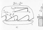
Schematic electrical diagram of the constant current regulator.
A graph explaining the operation of the power unit, made according to a single-phase bridge asymmetric circuit (U2 is the voltage coming from the secondary winding of the welding transformer, alpha is the thyristor opening phase, t is the time).
The regulator can be connected to any welding transformer with a secondary voltage U2 = 50. 90B. The proposed design is very compact. Overall dimensions do not exceed the dimensions of a conventional unregulated bridge-type rectifier9raquo; for direct current welding.
The regulator circuit consists of two blocks: control A and power B. And the first is nothing more than a phase-pulse generator. It is made on the basis of an analogue of a single-junction transistor assembled from two semiconductor devices of n-p-n and p-n-p types. The variable resistor R2 is used to regulate the direct current of the structure.
Depending on the position of the R2 slider, the capacitor C1 is charged here to 6.9 V at different rates. When this voltage is exceeded, the transistors open abruptly. And C1 begins to discharge through them and the winding of the pulse transformer T1.
The thyristor, to the anode of which a positive half-wave approaches (the pulse is transmitted through the secondary windings), opens at the same time.
Industrial three-winding TI-3, TI-4, TI-5 with a transformation ratio of 1: 1: 1 can be used as a pulse one. And not only these types. For example, good results are obtained by using two two-winding TI-1 transformers with a series connection of the primary windings.
Moreover, all the above types of TIs make it possible to isolate the pulse generator from the control electrodes of the thyristors.
There is only one "but9raquo;" The power of the pulses in the secondary windings of the TI is insufficient to turn on the corresponding thyristors in the second (see diagram), power block B. The exit from this "conflict9raquo; the situation was found to be elementary. To turn on the powerful, low-power thyristors with high sensitivity to the control electrode are used.
Power block B is made according to a single-phase bridge unbalanced circuit. That is, the thyristors work here in one phase. And the shoulders on VD6 and VD7 work as a buffer diode when welding.
Mounting? It can also be made mounted, based directly on the pulse transformer and other relatively “large-sized9raquo; elements of the circuit. Moreover, the radio components connected into this design, as they say, are minimum-minimum.
The device starts working immediately, without any adjustments. Collect one for yourself - you will not regret it.
A. CHERNOV, Saratov. Model constructor 1994 №9.
Heading: "Electronic homemade products"
Simple electronic regulator of welding current, diagram
Often it is necessary to cook metal of different thickness and use electrodes of different diameters, and in order for the welding to be of high quality, it is necessary to adjust the welding current so that the seam lies flat and the metal does not splash. But, it is quite problematic to regulate the current of the secondary winding of the welding transformer, because it can reach up to 180-250A.
As an option, nichrome spirals are used to adjust the welding current, including them in series in the primary or secondary winding of the welding transformer, or throttles. It is inconvenient to regulate the current in this way, and the regulator itself turns out to be cumbersome. But there is another way out - to make an electronic regulator of the welding current, which would regulate the current in the primary winding of the welding machine.
The welding current regulator for a homemade welding machine is still very useful in those cases when you have to weld metal in places where there is a weak power grid, in villages, for example. As a rule, the current consumption for each house is limited there, putting an input circuit breaker for 16 A, i.e. you can not turn on a load of more than 3.5 kW. A good welding machine, welding with electrodes with a diameter of 4-5 mm, consumes 6-7, or even 8 kW.
Therefore, we reduced the welding current and at the same time reduced the consumption current of the swap machine, thus invested in those 3.5 KW and welded what you need with a "C".
Here is a simple circuit of such a regulator on 2 thyristors and it has a minimum of non-scarce parts. It can be done on 1 triac, but, as practice has shown, it is more reliable on thyristors.
The welding current regulator works as follows: a regulator is sequentially connected to the primary winding circuit, which consists of two controlled thyristors VS1 and VS2 (T122-25-3, or E122-25-3), for each half-wave. The moment of opening of the thyristors is determined by the RC circuit (R7, C1, C2). By changing the resistance R7, we change the moment of opening the thyristors and thereby change the current in the primary winding of the transformer, and therefore the current in the secondary winding also changes.
Transistors can be used of the old model - P416, GT308, their lecco can be found in old receivers or televisions, and capacitors are used like MBT or MBM for an operating voltage of at least 400 V.
Transistors VT1, VT2 and resistors R5, R6, connected as shown in the diagram, are analogous to dinistors and in this version they work better than dinistors, but if you wish, instead of VT1, R5 and VT2, R6, you can put ordinary dinistors - such as KH102A.
When assembling and adjusting the welding current regulator, do not forget that the control takes place under a voltage of 220V. Therefore, in order to prevent electric shock, all radioelements, as well as thyristor heat sinks, must be isolated from the case!
In practice, the above mentioned electronic regulator of welding current has proven itself well.
The material is taken as a basis from the magazine Radioamator. - 2000.-№5 "Do-it-yourself welding transformer".
Recently I talked with my teacher at the university, and unfortunately revealed my radio amateur talents. In general, the conversation ended with the fact that I undertook to assemble a thyristor rectifier with a smooth current regulator for his welding "donut 9". Why is this needed? The fact is that alternating voltage cannot be cooked with special electrodes designed for a constant, and given that welding electrodes come in different thicknesses (most often from 2 to 6 mm), then the current value must be proportionally changed.

Choosing a welding regulator circuit, I followed the advice of -igRomana- and settled on a rather simple regulator, where the current is changed by applying pulses to the control electrodes, formed by an analogue of a powerful dynistor, assembled on a KU201 thyristor and a KS156 zener diode. See the diagram below:
Despite the fact that an additional winding with a voltage of 30 V was required, I decided to make it easier, and in order not to touch the welding transformer itself, I put a small additional 40 watts. Thus, the controller attachment has become completely autonomous - it can be connected to any welding transformer. The rest of the parts of the current regulator were assembled on a small board made of foil-coated PCB, the size of a pack of cigarettes.


As a base, I chose a piece of vinyl plastic, where I screwed the TC160 thyristors with radiators themselves. Since there were no powerful diodes at hand, two thyristors had to be made to perform their function.


It is also attached to a common base. To enter the 220 V network, terminals are used, the input voltage from the welding transformer is supplied to the thyristors through the M12 screws. We remove the constant welding current from the same screws.

The welding machine is assembled, it's time for testing. We feed the regulator a change from the torus and measure the output voltage - it almost does not change. And it should not, since at least a small load is needed to accurately control the voltage. It can be a simple 127 (or 220 V) incandescent lamp. Now, without any testers, a change in the brightness of the lamp filament is visible, depending on the position of the slider of the resistor-regulator.

So it is clear why the second trimming resistor is indicated according to the diagram - it limits the maximum value of the current that is supplied to the pulse shaper. Without it, the output already from half of the engine reaches the maximum possible value, which makes the regulation not smooth enough.

For the correct setting of the current range, the main regulator must be brought to the maximum current (minimum resistance), and the trimmer (100 Ohm) gradually reduce the resistance until its further decrease leads to an increase in the welding current. Fix this moment.


Now the tests themselves, so to speak, for the hardware. As intended, the current is normally regulated from zero to maximum, however, the output is not a constant, but rather a pulsed constant current. In short, the DC electrode neither cooked nor does it cook properly.

We'll have to add a capacitor bank. For this, 5 pieces of excellent electrolytes were found at 2200 uF 100 V. By connecting them using two copper strips in parallel, I got just such a battery.

We carry out tests again - the direct current electrode seems to have begun to cook, but a bad defect was found: at the moment of touching the electrode, a microexplosion and adhesion occurs - this is the capacitors being discharged. Obviously, you can't do without a throttle.

And then luck did not leave us with the teacher - in the locker there was just an excellent choke DR-1S, wound with a copper bus 2x4 mm along the W-iron and having a weight of 16 kg.


Quite another matter! Now there is almost no sticking and the DC electrode cooks smoothly and efficiently. And at the moment of contact there is not a microexplosion, but a type of slight hiss. In short, everyone is happy - the teacher is an excellent welding machine, and I get rid of the head clogging with an archimandrite subject that has nothing to do with electronics :)
How to make a simple current regulator for a welding transformer
 An important design feature of any welding machine is the ability to adjust the operating current. In industrial devices, different methods of adjusting the current are used: shunting with the help of chokes of all kinds, changing the magnetic flux due to the mobility of the windings or magnetic shunting, the use of active ballast resistors and rheostats. The disadvantages of such an adjustment include the complexity of the design, the bulkiness of the resistances, their strong heating during operation, and the inconvenience when switching.
The most optimal option is to make it with taps even when winding the secondary winding and, by switching the number of turns, change the current. However, this method can be used to adjust the current, but not to adjust it over a wide range. In addition, the regulation of the current in the secondary circuit of the welding transformer is associated with certain problems.
So, significant currents pass through the regulating device, which leads to its bulkiness, and for the secondary circuit it is almost impossible to select such powerful standard switches so that they can withstand a current of up to 200 A. Another thing is the primary winding circuit, where the currents are five times less.
After a long search, through trial and error, the optimal solution to the problem was found - the well-known thyristor controller, the circuit of which is shown in Fig. 1.

With the utmost simplicity and accessibility of the element base, it is easy to operate, does not require settings and has proven itself well in work - it works only as a "clock".
Power regulation occurs when the primary winding of the welding transformer is periodically disconnected for a fixed period of time at each half-cycle of the current. In this case, the average value of the current decreases.
The main elements of the regulator (thyristors) are connected opposite and parallel to each other. They alternately open with current pulses generated by transistors VT1, VT2. When the regulator is connected to the network, both thyristors are closed, the capacitors C1 and C2 begin to charge through the variable resistor R7. As soon as the voltage on one of the capacitors reaches the voltage of the avalanche breakdown of the transistor, the latter opens, and the discharge current of the capacitor connected to it flows through it.

Following the transistor, the corresponding thyristor also opens, which connects the load to the network. After the beginning of the next, opposite in sign, half-cycle of the alternating current, the thyristor closes, and a new cycle of charging the capacitors begins, but already in reverse polarity. Now the second transistor opens, and the second thyristor reconnects the load to the network.
By changing the resistance of the variable resistor R7, you can adjust the moment of turning on the thyristors from the beginning to the end of the half-period, which in turn leads to a change in the total current in the primary winding of the welding transformer T1. To increase or decrease the adjustment range, you can change the resistance of the variable resistor R7 up or down, respectively.
Transistors VT1, VT2, operating in avalanche mode, and resistors R5, R6, included in their base circuits, can be replaced by dinistors. The anodes of the dinistors should be connected to the extreme terminals of the resistor R7, and the cathodes should be connected to the resistors R3 and R4. If the regulator is assembled on dinistors, then it is better to use devices of the KN102A type.
Variable resistor of the SP-2 type, the rest of the MLT type. Capacitors of the MBM or MBT type for an operating voltage of at least 400 V.

A properly assembled regulator does not require adjustment. You just need to make sure that the transistors are stable in the avalanche mode (or in the stable switching on of the dinistors).
Attention! The device has a galvanic connection to the mains. All elements, including thyristor heat sinks, must be isolated from the case.
j &; electrician In o - electrical engineering and electronics, home automation; and much more for electricians and their homes.
Information and tutorials for the new electrician.
Key &; s, example and technical solutions, obk &; ies of interesting electrical innovations.
The information on the l &; website j &; electrician in about is provided in the ok &; accumulative and naval spruces. The administration of this website is not responsible for the use of this information. Say you can get materials 12+
Interpretation of materials of the l &; website k &; is prohibited.
Assembling homemade DC welding machines
- Welding machine: arc characteristic
- Dynamic characteristic
- Possible details and calculations
- Schematic diagram
- Welding scheme operation:
- Transformer and chokes design
- Apparatus design
- Parts and materials of the welding device:
- Assembly tools
To make homemade DC welders, you will need a high-power power source that converts the rated voltage of a conventional single-phase network and provides a constant value (in amperes) of the appropriate current to directly generate and hold a normal arc.

Diagrams of a homemade DC welding machine.
The power source of increased power is a circuit of the following components:
- rectifier;
- inverters;
- current and voltage transformer;
- current and voltage regulators that improve the quality characteristics of the electric arc (thyristors, triacs);
- auxiliary devices.
In fact, based on the homemade schemes, the transformer was and remains the source of the electric arc, even if you do not use auxiliary nodes and circuits of various control units.
Homemade device: block diagram

Schematic diagram of the power supply unit of the welding machine.
The power supply fits into a suitable plastic or metal box. It is supplied with the necessary elements: connectors, various switches, terminals and regulators. The welding machine can be equipped with carrying handles and castors.
Such a construction of a fairly good quality of welding can be done independently. The main secret of such a device is a minimal understanding of the welding process, the choice of material, as well as the skill and patience in the manufacture of this device.
But to assemble the device yourself, you must at least understand and study the basic skills, the moment of the appearance and combustion of the electric arc and the theory of electrode melting. Know the characteristics of welding transformers and their magnetic circuits.
Back to the table of contents
Homemade device: transformer
The basis of any scheme of a welding device is a transformer that lowers the normal voltage (from 220 V to 45-80 V). It operates in a special arc mode with maximum power. Such transformers are simply required to withstand very high currents with a nominal value of about 200 A. Their characteristics must be consistent, the I - V characteristic of the transformer must certainly fully comply with special requirements, otherwise it cannot be used for arc welding mode.
Welding machines (their designs) vary greatly. The variety of self-made welding transformers is huge, because there are a lot of truly unique solutions in the designs. In addition, self-made transformers are very simple: they do not have additional devices designed to directly adjust the current of the structure, which flows:

The design of a homemade semi-automatic welding machine.
- with the help of highly specialized regulators;
- by switching a certain number of turns of the coils.
The transformer mainly consists of the following elements:
- The magnetic core is metal. It is carried out by means of a set of transformer steel plates.
- Windings: primary (mains) and secondary (working). They come with leads for adjustment (by switching) or for a device circuit.
When calculating a transformer for the required current, cooking is carried out, as a rule, immediately from the working winding, without hanging circuits and various elements of limitation and regulation. The primary winding must be performed with terminals, taps. They serve to increase / decrease the current (for example, to adjust the transformer at low mains voltage).
The main part of any transformer is its magnetic circuit. In the manufacture of homemade developments, magnetic circuits are used from decommissioned stators of electric motors, old television and power transformers. Therefore, there is a huge variety of various magnetic circuits developed by folk craftsmen for such devices.
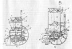
![]()
Welding transformer based on the widespread LATR2 (a).
- dimensions of the magnetic circuit;
- windings - the number of turns;
- input-output voltage level;
- I p - current consumed;
- I max - maximum output current.
Additional characteristics are simply impossible to evaluate or measure at home, even with the help of instruments. But it is they who determine the suitability of the transformer of the apparatus for the formation of a high-quality seam when powered in the welding mode by hand.
It directly depends on how the transformer "holds the current" and is called the external VAC (VVAC) of the power supply.
VVAC - the dependence of the potentials (U) at the connectors and the welding current, which changes from the load properties of the transformer and from the electric arc.
For welding by hand, only a steeply falling characteristic is used, and in automatic machines, a flat and rigid one is used.