CCFL or LED?
The actively developing LED industry could not help but influence the industry LCD displays, now it does not matter if it is the screen of a phone, tablet, laptop, monitor or TV. LED or, in other words, LED backlighting of matrices has almost completely replaced the backlighting on CCFL and EEFL lamps. And this is quite logical, LED backlighting has much more advantages, such as high efficiency, long service life, no mercury, no burnout and wide color gamut.
But what if your laptop has CCFL backlighting and it is out of order? Should I put the CCFL lamp back on or replace it with an LED backlight? My advice is the following: if this laptop is dear to you, and you do not plan to sell or donate after the repair, then it is better to install LED backlighting and forget about the problem of CCFL lamps burning out forever. Yes, in some cases it can get a little more expensive, and replacement requires some technical skills, but in this article I will try to tell you about one of the ready-made kits for such a modification of your laptop screen, which can help you when choosing and installing the kit.
Features of the CA-166 LED backlight kit and circuit design
LED backlight set CA-166, designed to replace backlight lamps with LEDs in laptops of different diagonal. Appearance backlight is shown in the figure below.
General view of LED backlight with diode strip
The form factor of the board is specially designed for installation in laptops instead of the classic CCFL backlight... On the left side, the board has a connector with 4 pins: "+ Power", "ground", "backlight on", "brightness control". On the second side there is a connector for connecting an LED strip.
The DF6113 chip is used as a LED backlight driver. You can view the datasheet for DF6113 here. The controller is a specialized controller designed specifically to operate in the power supply circuits of the LED backlight of the LCD display.
The DF6113 microcircuit is capable of operating at an input voltage of 5 to 24V and at the same time maintaining a constant current value on the LEDs. Looking ahead, I want to note who the circuitry solution implemented in the CA-166 requires an input voltage of at least 10 volts, read more about this below. The controller supports linear dimming in a range as claimed by the manufacturer from 10 to 100% (1:10). But it is worth making a reservation that this is true when using the connection scheme proposed by the manufacturer. If you make simple changes, you can expand the brightness adjustment range to 1:40.
Brightness control is possible, both direct and inverse. In addition, DF6113 has soft start function, overvoltage protection function and short circuit... The CA-166 LED backlight adopts these functions accordingly.
Connectable LED Strip Light consists of LEDs connected in parallel-series in groups of 3 pcs. If necessary, you can shorten the tape to the desired length, but keeping the diode ratio equal to three.
Note! When shortening the tape, it is desirable to change the driver stabilization current, otherwise, at maximum brightness, the backlight LEDs may begin to degrade from heating, which will shorten their service life. How to change the current will be written later.
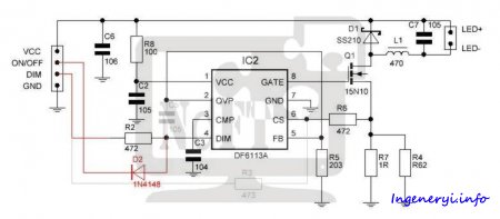
Let's consider a schematic solution. The illumination circuit is shown in Fig ...
 |
LED backlight circuit on the DF6113A controller
The location of the inductor says that it is built on the principle of a step-down DC-DC converter, hence the limitation on the minimum input voltage mentioned earlier. For the backlight to work, you need a voltage equal to the power supply 3x sequential LEDs(average 9.6V) + 420mV voltage feedback... Therefore, the supply voltage must be at least 10V and no more than 24V (microcircuit limitation). Resistors R4 and R7 are used to set the operating current of the LED backlight. The current strength is chosen on the basis that one section of three diodes at maximum brightness consumes about 20mA. And based on these data, they are calculated using the formula Imax = 420mV / Rout. The table below shows the recommended resistance values.
|
Diagonal, inch |
Length of tape, mm |
Number of diodes, pcs |
|
|
15 ”square |
|||
|
14 "wide. |
|||
|
14 ”square |
|||
|
13.3 "wide. |
|||
|
12 ”square |
|||
|
12 "wide. |
|||
Using larger resistors will not damage the LEDs, but will only reduce the maximum brightness. Installing lower resistors is also possible, but with the obligatory activation of the laptop brightness adjustment function.
The brightness control is analog and occurs by changing the voltage level at the DIM pin. This decision was made in order to increase the versatility of the device, because when using this backlight in notebooks with PWM dimming, it will also work, but it is possible that the brightness level will not be dimmable. If you are not satisfied with the resulting brightness adjustment range, then you can carry out simple modifications described below.
Modification 1. Modification of the LED backlight for working with a PWM signal for dimming
This revision will slightly expand the range of brightness control and better adapt the board to work with a PWM control signal.
Below is a diagram in which the red lines indicate the introduced elements and connections, and the gray lines - deleted elements and connections.
 |
Scheme of changes in the LED backlight driver for working with a PWM dimming signal
For revision you will need
Diode 1N4148 or similar (in SMD SOD-323 * package)
2.2 ohm resistor ** (SMD 1206)
Resistor 3.0 Ohm ** (SMD 1206)
* The indicated types of enclosures are optional, but recommended, since they are very convenient to install on the board.
** The resistor values were selected for reasons of the gentle operation of the LED backlight. If necessary, you can use the resistance values from the table above.
Delete C5
Remove R3
Replace current resistors R4 and R7. Instead of 2 resistors, you can set one to 1.3 Ohm, while the maximum brightness will slightly decrease.
Install the 1N4148 diode diagonally, with the cathode to the left terminal of the resistor R3, and the anode to the lower terminal of the capacitor C5.
The photo below clearly shows the changes to the LED driver board. The locations of the changes are circled in red.
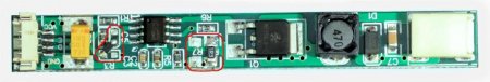 |
After this modification, the DIM input will be fully compatible with the PWM luminance signal. The trigger input is also fully PWM compatible. The current delivered by the driver at maximum brightness will be approximately 320mA. The minimum brightness depends on the duty cycle of the PWM signal. With a common PWM frequency of 60Hz, the minimum brightness is about 36mA, which corresponds to a 1: 9 brightness control. Since the PWM signal frequency in most laptops is only 60Hz, some people may notice slight flickering. If you need to get rid of it, then I recommend taking a look at the next revision, which is devoid of this drawback.
Refinement 2. Remove the influence of the PWM signal on the image
This refinement is somewhat more complicated than the previous one, but it gives more noticeable results. With this refinement, it is possible to completely get rid of brightness modulation, increase the conversion efficiency, and expand the brightness adjustment range up to 1: 100.
Below is a diagram with the indicated modifications
 |
For revision you will need
Diode 1n4148 (or similar in DO35 * package)
220kΩ resistor 1% accuracy
12kΩ resistor (SMD 0603)
Resistor 330kΩ (SMD 0603)
Capacitor 25V 0.1µF (SMD 0603 MLCC)
N-channel MOSFET (ZVN2106A, 2N7000 or analogs)
Resistor 1.8 ** Ohm (SMD 1206)
Resistor 3.9 ** Ohm (SMD 1206)
If it is necessary to expand the range of dimming, then it will also be necessary to replace the inductance L1, the nominal value of which is selected based on the requirements for dimming. The dependence of the brightness range on the inductance is shown in the following table:
* The given casing of elements is selected for ease of installation and is not a mandatory requirement.
** Resistor ratings are selected according to the length and consumed LED backlit current. See the table above.
Sequence of actions for revision
Remove capacitor C5.
Remove resistor R3.
Replace current-sensing resistors R4 and R7 with 1.8 Ohm and 3.9 Ohm resistors (or with those chosen from the table).
If necessary, replace the inductance L1 - 47µH with a larger inductance. This will reduce the minimum settable output current from 16 mA to 8 mA.
Replace resistor R6 with a 12kΩ resistor.
Solder the 330 kΩ resistor with one leg to pin 6 of the DF6113 microcircuit.
Solder the 0.1µF capacitor to the 7th leg of the DF6113 microcircuit.
Connect the free leads of the resistor from point 6 and the capacitor from point 7 together.
Solder the source field-effect transistor to the ground terminal of the resistor R5.
Solder the drain of the field effect transistor to the anode of the 1N4148 diode.
Connect the cathode of the 1N4148 diode at the point formed between the resistor and capacitor from step 8.
Connect the lead of the 220K resistor to the positive lead of the input tantalum capacitor C6. Connect the second terminal to the drain of the transistor, this is the terminal to which we previously connected the anode of the 1N4148 diode.
Solder the gate of the transistor to the left pad of the resistor R3.
When using surface mount components, be extremely careful not to short-circuit between leads.
The location of the parts can be seen in the following pictures:
After this modification, the PWM dimming signal will be converted to analog. This will eliminate possible flicker, result in more linear brightness control and wider range of brightness control.
Conclusion
The reviewed set of LED backlighting, which is designed specifically for CCFL replacements in laptop screens, has a number of advantages that compensate for some of the complexity of installation. The advantages include the affordability of the set, durability, improved color rendering, etc. Although the above design of the LED backlight driver board does not realize all the advantages of the DF6113 microcircuit, it can be easily fixed with a pair of common radio elements and a soldering iron.
TVs with liquid crystal LED screens capable of providing crisp images, sophisticated design and many useful features. In these models, the image is transmitted to the display using LED backlight, evenly spaced across the matrix area.
Signs of a broken LED backlight
A chain of LED lamps, consisting of many links, is responsible for the backlight function, therefore, breakdowns of its individual elements often occur. In the event that the backlight fails, LED TV there may be no picture, although sound is present and the unit reacts to commands from remote control: Switches channels, changes the volume level. If you look closely at the display, you can see a dark image and even distinguish the silhouettes of figures, but the damaged backlight makes it impossible to reproduce the picture as expected.
LED backlight LCD TV can fail for one of two reasons:
burnout of one or more LEDs ;
malfunction LED drivers
It is quite difficult to identify the cause of the breakdown, since checking all the links in the backlight chain is a long and painstaking work... The technician must measure the voltage at each LED and thus find the damaged one.
There is another way to check LED backlight - supply independent power to each backlight strip, thus finding out the strip on which the faulty LEDs are located, and then separately check each diode on this strip.
If all the elements are in order, then the cause of the breakdown lies in LED driver usually installed on the TV's power supply.
If the image looks distorted or twitches, the cause of the failure is driver malfunction, mechanical damage to the loops, or loss of contact. Also, the image may be distorted with a picture of normal brightness, the appearance of stripes and streaks in certain areas of the screen. It should be noted that the same symptoms occur when the loop contacts are broken, so it is important to correctly identify the problem. If, when you press the screen, the picture is restored or, conversely, new stripes appear, then the problem is in the loop and LED backlight it has nothing to do with it.
Breakdown reasons LED drivers
LED lights often gets out of standing even on TVs with LCD screens from leading brands. The main reason for the failure is overpowering: manufacturers by default adjust the image to maximum clarity and brightness in order to increase the product's appeal. Typically, customers use the preset settings and as a result, the current is supplied to LEDs exceeds acceptable level and the elements burn out quickly.
LED driver is a power supply for the backlight. With a constantly increased load, the electrolytic capacitors of the unit break off and the backlight is turned off. The breakage is easy to fix if you replace the part with a more powerful one. There are frequent cases when power surges occur in the power grid. In this case, one of the elements may fail. LED driver :
a transistor required to convert electrical impulses;
low-resistance resistor that serves as a fuse;
capacitors.
If one or more elements of the unit fail, the TV screen turns on for a short time and then goes out. In this case LED lights flashes for a few seconds, then the circuit is overloaded and the driver is completely turned off. This happens when overheating: the tightly closed housing of the unit has no ventilation and may malfunction when the temperature rises.
When the driver is overloaded, the overvoltage protection is triggered and the current supply to the backlight circuit is cut off. In this case, an open circuit occurs in the circuit and the backlight goes out.
If the LEDs are supplied with excessive power, the lamps quickly burn out. In this case, even with the naked eye, you can notice darkening on the back of the chain. The LED driver is responsible for stabilizing the voltage and, when the recommended load is exceeded, interrupts the current supply. With a standard current of 400mA, the load on LED lamp exceeds the norm and they fail after a short time. To avoid damage, it is necessary to limit the flow of electric current until the moment when the load becomes excessive. With a power of 300 mA, the brightness of the LCD screen will slightly decrease, but the heating temperature of the LED will drop by 35 ° C: from 95 to 60 degrees.
To fix such a breakdown, it is necessary to replace the electrolytic capacitors and do several ventilation holes in the block body.
In order to prevent the problem in advance and increase the life of the TV, it is necessary to reduce the brightness of the screen backlight set by the manufacturer. This will not affect the quality and clarity of the picture, the image will become more natural and easier to understand, and an expensive TV will last much longer.
The article is devoted to the repair of LED floodlight drivers. Let me remind you that recently I already had an article on, I recommend that you read it.
An article on LED driver circuits and their repair
Sasha, hello.
In particular, on the topic of lighting - diagrams of two modules from automotive LED floodlights with a voltage of 12V. At the same time, I want to ask you and the readers a few questions about the components of these modules.
I am not good at writing articles about the experience of repairing some electronic devices(this is mainly power electronics) I write only on the forums, answering questions from forum participants. In the same place I share the diagrams I sketched from devices that I had to repair. Hopefully schematics LED drivers, drawn by me, will help readers to repair.
I drew attention to the diagrams of these two LED drivers because they are simple, like a scooter, and it is very easy to repeat them with your own hands. If there were no questions with the YF-053CREE-40W module driver, then there are several of them according to the topology of the circuit of the second module of the TH-T0440C LED floodlight.
LED driver circuit of LED module YF-053CREE-40W
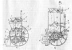
The appearance of this spotlight is given at the beginning of the article, and this is how this lamp looks from the back, the radiator is visible:
The LED modules of this spotlight look like this:
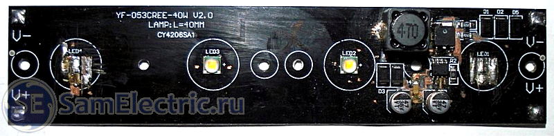
I have a lot of experience in drawing circuits from real complex devices, so I easily copied the circuit of this driver, here it is:
YF-053 CREE LED floodlight driver, wiring diagram
Schematic diagram of the TH-T0440C LED driver
What this module looks like (it is a car LED headlight):
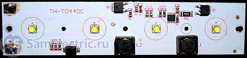
Electrical diagram:

There is more incomprehensibility in this scheme than in the first one.
Firstly, due to the unusual switching circuit of the PWM controller, I could not identify this microcircuit. In some connections, it is similar to the AL9110, but then it is not clear how it works without connecting its Vin (1), Vcc (Vdd) (6) and LD (7) pins to the circuit?
Also, the question arises about connecting the MOSFET Q2 and its entire strapping. After all, he has an N-channel, and is connected in reverse polarity. With such a connection, only its antiparallel diode works, and the transistor itself and all its "entourage" are completely useless. It was enough to put instead a powerful Schottky diode, or "button accordion" from the smaller ones.
LEDs for LED drivers
I could not decide on the LEDs. They are the same in both modules, although their manufacturers are different. There are no inscriptions on the LEDs (with back side- too). I was looking for different sellers on the line "Superbright LEDs for LED spotlights and LED chandeliers." They sell a bunch of different LEDs, but all of them, either without lenses, or with 60º, 90º and 120º lenses.
Maybe it will be interesting:
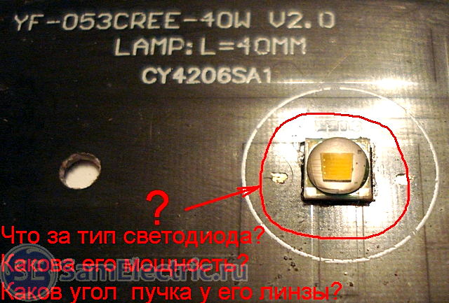
Similar in appearance to mine, I have never met.
Actually, both modules have one fault - partial or complete degradation of LED crystals. I think the reason is the maximum current from the drivers set by the manufacturers (Chinese) for marketing purposes. Like, look how bright our chandeliers are. And the fact that they shine from the power of 10 hours does not bother them.
If there are claims from buyers, they can always answer that the projectors are out of order from shaking, because such "chandeliers" are mainly bought by the owners of jeeps, and they drive not only on the highway.
If I can find LEDs, I will reduce the driver current until the brightness of the LEDs noticeably decreases.
It is better to look for LEDs on Aliexpress, there big choice... But this is roulette, as luck would have it.
Datasheets (technical information) for some powerful LEDs will be at the end of the article.
I think the main thing for the long-term operation of LEDs is not to chase brightness, but to set the optimal operating current.
Until next time, Sergey.
P.S. I have been "sick" with electronics since 1970, when I assembled my first detector receiver at a physics lesson.
More driver schemes
Below I will post a little information on the schemes and repair from me (the author of the blog SamElektrik.ru)
LED floodlight Navigator, considered in the article (I already gave a link at the beginning of the article).
The circuit is standard, the output current changes due to the ratings of the piping elements and the power of the transformer:

LED Driver MT7930 Typical. Typical electrical schematic diagram for LED floodlights
The circuit is taken from the datasheet for this microcircuit, here it is:
/ Description, typical scheme inclusions and parameters of the microcircuit for drivers of LED modules and matrices., pdf, 661.17 kB, downloaded: 787 times. /
The datasheet describes in detail what and how to change in order to get the desired output current of the driver.
Here is a more detailed diagram of the driver, closer to reality:

See the formula to the left of the diagram? It shows what the output current depends on. First of all, from the resistor Rs, which stands at the source of the transistor and consists of three parallel resistors... These resistors, and at the same time the transistor, burn out.
Having the circuit, you can start to repair the driver.
But even without a diagram, you can immediately say that first of all you need to pay attention to:
- input circuits,
- diode bridge,
- electrolytes,
- power transistor,
- soldering.
I myself have repaired just such drivers several times. Sometimes only helped complete replacement microcircuit, transistor and almost the entire strapping. It is very labor intensive and economically unjustified. As a rule, it is much easier and cheaper to buy and install a new Led Driver, or refuse to repair it altogether.
Download and Buy
Here are the datasheets (technical information) for some high-power LEDs:
/ Technical information on powerful LED for headlights and spotlights, pdf, 689.35 kB, downloaded: 151 times. /
/ Technical information on high-power LED for headlights and floodlights, pdf, 1.82 MB, downloaded: 194 times. /
Special thanks to those who have schematics of real LED drivers for the collection. I will post them in this article.
In the articles, we examined the operation of the backlight on CCFL lamps, which require ultra-high voltage. An inverter producing such a voltage must monitor the current of the lamps, match the output stage of the inverter with input impedance lamps, provide short circuit protection.
Backlighting on CCFL lamps has a more complex circuitry and significant power consumption. LED backlight is devoid of such disadvantages.
LED (Light Emitting Diode) or light emitting diode is a semiconductor device that converts electricity directly into light radiation. A low voltage is used to "light" the LED. It has high efficiency, long service life, no mercury, no burnout and wide color gamut.
Attention!!! There is a life-threatening voltage in the monitor, so everything that is further described in the article, you do at your own peril and risk!
We will change the backlight in the Samsung SyncMaster 2343NW monitor to LED. The backlight kit that will be used for replacement consists of two lines of high-brightness white LEDs and a DC driver through which the LEDs are controlled:
The LED driver is marked as CA-155 Rev: 02 and has the following pins
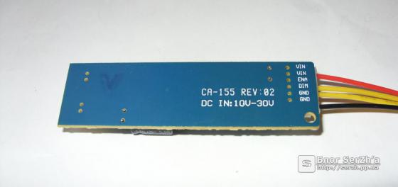
- VIN - plus power supply DC 10-24V (red wire)
- ENA - disable / enable backlight 0 - 3.3V (yellow wire)
- DIM - dimming LEDs 0.8 - 2.5V (yellow wire)
- GND - minus power supply (black wire)
![]()
The heart of the backlight driver is an ASIC (8-pin SOP-8L). I want to immediately draw your attention to the fact that the maximum voltage supply of the microcircuit is 24V according to the datasheet. With the specified value on the board at 30V, the microcircuit will not work for you for long !!! Chip capabilities:
- input voltage in the range from 5 to 24V
- smooth start
- brightness adjustment from 10% to 100%
- short circuit and overvoltage protection
- LED bar current control
The microcircuit supports three modes of brightness control - separate, single signal and mixed control. Inverted analog brightness control is implemented on the CA-155 module. Module dimensions 65mm x 20mm.
The LED line has the following marking CA-540-530MM-24W-96LED

The length of the LED strips I ordered is 537mm, which is more than enough for a 23 "Samsung SyncMaster 2343NW monitor.

The LED strip is a 4mm wide PCB strip, onto which 96 super-bright white LEDs SMD3528 with dimensions of 3.5 x 2.8 x 1.8 mm (L x W x H) are soldered. LEDs are connected in parallel-series in groups of 3 pcs. The supply voltage of the group is 9.6V. If necessary, the tape can be shortened to the desired length, while maintaining the diode ratio equal to three.
Installing LED backlight
For LED installations backlighting, we need double-sided white or transparent tape. The width of the LED bar is such that it fits exactly into the groove where they used to stand CCFL lamps First, we need to cut the LED strip to the required length. In my case, I had to cut off the three outermost LEDs. After shortening the LED strips, we re-check them in operation. We glue the tape on the underside of the ruler and free the other side of the tape from the film, glue the LED rulers into the grooves on the top and bottom. It is very important to bring the wires of the LED line out from the side where they were taken out earlier.

Now you can put on the white reflective tape, diffuse plexiglass and check before the final assembly of the matrix. If done correctly, you will see a solid color bright backlight screen. Then we collect everything in the reverse order, according to the instructions described in the first part of the article.
Moving on to the inverter board and making a little revision. To do this, we solder fuse F41, through which + 16V is supplied to the inverter power supply. In my case, the inverter transformer was also dropped, due to the burned out winding.
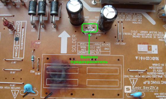
Let's figure out the signals that we need to connect the DC driver to the combo board.

The required signals are marked with rectangles:
- "Pin 2" + 16V plus driver power supply
- "Pin 3" GND minus power supply of the driver
- "Pin 7" A-DIM brightness adjustment
- "Pin 8" ON / OFF turn on / off the backlight
Let's see why A-DIM and not B-DIM. I've experimented with both signals. The difference between the signals is that the first is used for analog dimming. The A-DIM signal is generated by the monitor microprocessor and changes the magnitude of the DC voltage. An increase in the A-DIM signal leads to an increase in the feedback voltage and vice versa. However, when adjusting the brightness from the monitor control panel, the value changes only in the range from 1 to 10 units. This is quite enough for me.
Perhaps someone wants to use the PWM signal to adjust the brightness, then you need to connect to "Pin 1" of the B-DIM. The B-DIM signal is low frequency pulses that follow at a specific frequency. By adjusting the brightness, the width of these pulses changes. It is the width of these pulses that determines the width of the "packs" alternating current... When this DC driver is connected to the B-DIM, the brightness control is inverted, that is, when the value is increased from 0 to 100, the brightness value changes from 100 to 10. This can be bypassed if the DC driver is modified according to this scheme. On some forums, users complain that their eyes get tired faster with LED backlighting. some eyes are sensitive to backlight flicker. This affects the PWM dimming, but this can also be corrected if the DC driver is modified according to a different scheme.
From all of the above, I chose the connection to A-DIM without modifications. The limits of changing the brightness control completely suit me.
Let's go back to connecting the DC driver to the combo board. The wires with the connector included in the kit are pretty short, so I called the track tester on the board and soldered the wires to the nearest sections. That's what I did:
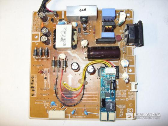
I positioned the DC backlight driver board so that it was on the main board of the inverter and there was free access to the connection of the LED strips. I put the driver board itself on hot melt glue. You can now test the backlight and reassemble the monitor. After assembling all the boards, connecting the LEDs turned out to be quite convenient.

After final assembly I wanted to check the consumption of the monitor at full brightness. According to the passport data, the consumption of the Samsung SyncMaster 2343NW monitor is 44W. After installing the LEDs, the consumption was 23.8W, almost two times less!

After installing the LEDs, the monitor began to "turn green" a little, but this is solved by adjusting the RGB channels in the monitor or video card menu. Brightness and contrast are enough, the picture is quite juicy.

Summing up
Minuses:
- White balance slightly shifted towards green tones
- Dimming with PWM can produce a flickering effect
Pros:
- Minimum consumption when using LEDs
- Sufficient brightness and contrast of the screen
- Simpler circuitry than CCFL inverter
- Absence high voltage, heating and burnout like CCFL lamps
- Longer life compared to CCFL lamps
Rapid development LED technology made it possible to reduce the dimensions of equipment, improve their characteristics, and most importantly, significantly reduce energy consumption, which in our time is one of the most important indicators.