Often, in the manufacture of various devices, it becomes necessary to use LEDs and LED indicators. The connection of the LED to the power supply is carried out, as a rule, through a current limiting resistor (damping resistor). Below are the principles and formulas for calculating a damping resistor, as well as a small calculator for quick calculation.
Calculation of a damping resistor for an LED
First of all, we will figure out how to calculate the resistance of the damping resistor, what it depends on and what power the resistor should be to power the LED from the power source.

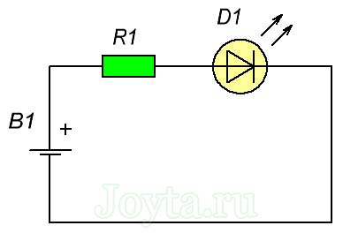
Rice. 1. Diagram of connecting an LED to a power source through a resistor.
As you can see from the diagram, the current (I) through the resistor and the LED flows the same from the same. The voltage across the resistor is equal to the difference between the supply voltage and the voltage across the LED (VS-VL). Here we need to calculate the resistance of the resistor (R), at which voltage I will flow through the circuit, and the voltage VL will be on the LED.
Let's say that we will power the LED from the battery. voltage 5V, as a rule, such a supply voltage is used when powering microcontroller circuits and other digital equipment.
Let's calculate damping resistor voltage, for this we need to know the voltage drop across the LED, this can be found out in the reference book for a specific LED.
Approximate voltage drop values for LEDs (AL307 and others low-power in a similar case):
- red - 1.8 ... 2V;
- green and yellow - 2 ... 2.4V;
- white and blue - 3 ... 3.5V.
Let's say we will use blue LED , the voltage drop across it is 3V.
We calculate the voltage across the damping resistor:
Ugrez = Usup - Ulight = 5V - 3V = 2V.
For calculating the resistance of the damping resistor we need to know the current through the LED. The rated current of a specific type of LED can be found in the reference book. Most have little high-power LEDs(like AL307) rated current is in the range of 10-25mA.
Let's say that for our LED rated current for its bright enough glow is 20mA (0.02A). It turns out that a voltage of 2V will be extinguished on the resistor and a current of 20mA will pass. Let's perform the calculation according to the Ohm's law formula:
R = U / I = 2V / 0.02A = 100 Ohm.
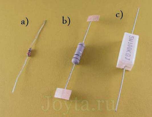
In most cases, a low-power resistor with a power of 0.125-0.25W (MLT-0.125 and MLT-0.25) is suitable. If the current and voltage drop across the resistor is very different, then it does not hurt to produce resistor power calculation:
P = U * I = 2V * 0.02A = 0.04 W.
Thus, 0.04 W is clearly less than the rated power even for the smallest MLT-0.125 resistor (0.125 W).
Let's make a calculation for red led (voltage 2V, current 15mA).
Ugrez = Usup - Ulight = 5V - 2V = 3V.
R = U / I = 3V / 0.015A = 200 Ohm.
P = U * I = 3V * 0.015A = 0.045 W.
A simple calculator for calculating a damping resistor
LED is a device that emits light when current passes through it.
Depending on the type of material used to make the device, LEDs can emit light different colors... These miniature, reliable, economical devices are used in engineering, lighting and advertising purposes.
The LED has the same current-voltage characteristic as a conventional semiconductor diode. In this case, with an increase in the forward voltage on the LED, the current passing through it increases sharply.
For example, for a green LED type WP710A10LGD from Kingbright, when the applied forward voltage changes from 1.9 V to 2 V, the current changes 5 times and reaches 10 mA. Therefore, when the LED is directly connected to a voltage source, with a small voltage change, the LED current can rise to a very high of great importance which will lead to combustion p-n transition and LED.
carried out using letters and numbers, with which you can determine quality characteristics devices.
Therefore, at parallel connection LEDs are usually connected to each device in series with its own limiting resistor. The calculation of the resistance and power of such a resistor is no different from the previously considered case.
When the LEDs are connected in series, it is necessary to turn on devices of the same type.
In addition, it must be borne in mind that the voltage of the source must be no less than the total operating voltage of the entire group of LEDs.
The calculation of the current limiting resistor for the series LEDs is considered the same as before. The exception is that when calculating, instead of the value of Ub, the value of Ub * N is used. In this case, N is the number of devices turned on.
Conclusions:
- LEDs are widespread devices used in technology for lighting and advertising.
- Limiting resistors are often used to avoid LED damage due to their sensitivity to voltage changes.
- The calculation of the resistance value of the limiting resistor is done based on Ohm's law.
Resistor calculation for connecting LEDs on video
Being a semiconductor device, it has a nonlinear current-voltage characteristic (VAC); the dependence of current on voltage is exponential. Even a slight excess of the supply voltage can cause the appearance of a current that can disable the LED (hereinafter LED).
Therefore, to limit the current, an ordinary resistor is used as a damping ballast, the operation of the LED and its service life depend on the correct calculation of the resistance.
With a supply voltage exceeding the operating voltage range, the LED can simply burn out, with an underestimated voltage, it either shines “half-burned” or does not turn on at all.
Resistor Resistor Calculator for LEDs
The calculator can be used to calculate the resistance of a resistor for one or more, LEDs connected in series (!). The resistance value of the resistor is selected from the nearest of greater importance standard row.
When calculating on the proposed calculator, such initial data as the number of LEDs in the circuit and their connection scheme, as well as the forward voltage, LED current and the value of the supply voltage are used.
To determine the forward voltage a of the LED current in the absence of technical documentation, the forward voltage can be determined based on the color of the diode glow (see table below). Please note that the forward voltage values given in the table will be correct for LEDs rated for 20 mA.
LED connection diagrams
If a single resistor is sufficient to daisy chain several LEDs to a power supply to limit the current, then parallel connection we should avoid using one damping resistor (see diagrams).

This is due to the fact that, due to even a small difference in the LED's own resistances, for the correct operation of each, an individual voltage value is required.
Otherwise, one or more LEDs will glow noticeably brighter than the others, consuming, respectively, more current, which is fraught with acceleration of the process of degradation of diode crystals and their rapid failure.
Therefore, when connected in parallel, each LED should be provided with its own current-limiting resistor.
Speaking about connecting the LED, one cannot but mention the obligatory observance of the polarity of the connection: the “positive” conductor must be connected to the anode of the diode, and “negative” conductors from the power source must be connected to the cathode.
To determine the required resistance of the current limiting resistor for one or more LEDs, the following information is required:
Power supply voltage;
- the forward voltage of the LED and the current for which it is designed;
- the number and connection diagram of LEDs.
In the absence of reference data, the forward voltage of the LED can be quite accurately determined by the color of its glow using the table:
Most of these modern semiconductor devices are designed for a current of 20 mA, however, there are diodes designed for high currents (150 mA or more). Therefore, for an accurate determination of the rated current, the technical data of the diode brand will be required.
In the complete absence of data on the brand and technical characteristics We recommend taking the LED as the nominal current 10 mA and the forward voltage 1.5-2 V.
The choice of the connection diagram for semiconductor devices depends on required amount damping resistors. So, when they are connected in series, one thing is quite enough: at all points the values of the flowing current are the same.
When diodes are connected in parallel, the use of one common damping resistor is unacceptable. Due to the fact that there are no LEDs with exactly the same characteristics; having a certain spread in resistances and, accordingly, consumed currents, an element with a lower resistance will consume more current, which can cause its premature failure.
Thus, if one of several parallel-connected LEDs burns out, an increased voltage will go to the rest due to the resistance of a resistor designed for a certain number of diodes, for which they are not designed, which, in turn, will cause them to fail.
Therefore, when connecting LEDs in parallel, it is recommended to provide a separate resistance for each element. In the proposed calculator this recommendation taken into account.
The calculation is made according to the formula:
R = U damping / I LED;
U damping = U power supply – U LED.
Important! Be sure to observe the correct polarity of the LEDs. The anode (longer lead) is connected to the plus of the power source, the cathode is connected to the minus (there is a characteristic cut on the diode bulb on its side).
Today we will start by examining a new element, namely the LED. Basic information about the LED is collected in a separate article.
The LED basically has 2 leads: the long lead (anode) is connected to the positive of the power supply, the shorter lead (cathode) is connected to the negative. The LED connected on the contrary will not light up, and in addition, if a certain voltage is exceeded, it may even burn out.
Where to start when working with an LED? From viewing technical parameters to a specific LED! Sometimes the information we need can also be obtained when purchasing from a store. What do we need to know? What we are looking for is forward current and forward voltage.
For an LED, the main thing is the correctly selected current, since it directly affects the life of the LED. Therefore, we say that an LED is an element powered by something com (not energized!).
When looking at the datasheet for 5mm single color LEDs, here's what I found:
- red LED: 20mA / 2.1V
- green LED: 20mA / 2.2V
- yellow LED: 20mA / 2.2V
- orange LED: 25mA / 2.1V
- blue led indicator: 20mA / 3.2V
- LED white: 25mA / 3.4V
(LED parameters may vary slightly depending on the instance and LED manufacturer)
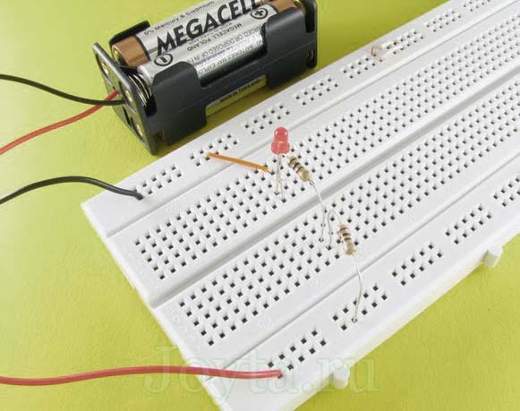
Our power supply, as in the previous exercises, is a cassette of 4 batteries, giving a voltage of about 6 volts. Now the question arises: how to choose a resistor to limit the current of a red LED connected according to the following diagram:
Our battery provides a voltage of about 6 volts. The red LED needs a current of about 20mA. Plus, you need to take into account the voltage drop across this LED, i.e. 2.1 volts:
U R1 = U B1 - U D1
U R1 = 6V - 2.1V
Now it's enough to substitute our data into the formula:
R1 = 3.9V / 20mA
R1 = 3.9V / 0.02A
So here in a simple way we calculated the resistance of the resistor R1 for the red LED, which must have a minimum resistance of 195 ohms. But you won't be able to find such a denomination! What to do in this case? It is necessary to take from a resistor of a larger value, but with the closest possible resistance.
The closest resistor in the nominal row of resistors is a 200 ohm resistor, and this is what we should use in our circuit. Why? Of course, nothing prevents us from using a resistor with a higher resistance, for example, 470 Ohm, 2.2 kOhm ... But how will this affect the glow of our LED? Let's check!
In the photo, this is certainly not noticeable, but the LED shines very brightly with a 200 Ohm resistor. But what happens if we replace the resistor with another one with a higher resistance, for example, 470 ohms? The LED is still on. Then we will sequentially increase the resistance: 2.2 kOhm, 3.9 kOhm, 4.7 kOhm ... Please note that the LED shines weaker and weaker as the resistance of the resistor increases, until finally it stops glowing at all.
One more note in essence - it is necessary to use resistors slightly larger than it follows from the calculations (for example, 210 ohms instead of 200 ohms). Why? You probably noticed that for the calculations we took the nominal voltage of our battery, in reality, fresh batteries can give more high voltage and therefore, the resistance of the resistor may be insufficient. The current on the LED will be higher than required, which ultimately will affect its service life.
Another example from life (or rather from frequently asked questions). How to choose a resistor for a circuit (in a car) in which two red LEDs are connected in series (forward current 20 mA, forward voltage 2.1 V)?
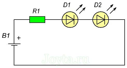
We calculate the resistance value of the resistor R1 in the same way as in the example above, with the only difference that from the voltage of the vehicle's on-board network (14V), it is necessary to subtract the voltage drop across both diodes D1 and D2:
U R1 = U E1 - U D1 - U D2
U R1 = 14V - 2.1V - 2.1V
Now let's substitute the data into the formula:
R1 = 9.8V / 20mA
R1 = 9.8V / 0.02A
Resistor R1, to which two red LEDs are connected in series, must have a minimum resistance of 490 ohms. The closest in the row is a 510 ohm resistor. If you do not have a 510 ohm resistor, remember that you can connect multiple resistors in series, for example 5 100 ohm resistors.
And can we connect 5 more LEDs in series in this circuit? No! There is some voltage drop on each of the connected LEDs, in other words, each of them consumes a certain amount of voltage, for example, each red LED needs 2.1 volts. It is easy to calculate that our battery is not able to provide such a voltage:
14B< 2,1В + 2,1В + 2,1В + 2,1В + 2,1В+ 2,1В + 2,1В
14B< 14,7В
The above example is for a circuit installed in a car where the voltage source is 14V.

The next example will deal with the parallel connection of LEDs, as shown in the following figure:

This time, let's say LED D1 is red (forward current 20mA, forward voltage about 2.1V) and LED D2 has White color(forward current 25mA, forward voltage 3.4V).
From the first Kirchhoff's law we know that:
I = 20mA + 25mA
When connecting LEDs in parallel with the power supply, remember that each LED must have its own resistor! Now let's calculate the voltage drop across each of the resistors:
U R 1 = U B 1 - U D 1
U R1 = 6V - 2.1V
U R 2 = U B 1 - U D 2
U R2 = 6V - 3.4V
We know the current and voltage, let's calculate the resistance:
R1 = U R 1 / I 1
R1 = 3.9V / 20mA
R1 = 3.9V / 0.02A
R2 = 2.6V / 25mA
R2 = 2.6V / 0.025A
Resistor R1 must have a resistance of at least 195 ohms (the closest resistor in the nominal row is 200 ohms), and resistor R2 must have a resistance of at least 104 ohms (the closest in the row will be 120 ohms).

What is the best way to connect LEDs: in series or in parallel? The answer is not easy, because both options have their pros and cons:
|
LED connection type |
|
|
consistent |
parallel |
| one LED is enough for all LEDs resistor |
each LED must have its own resistor |
| damage to one LED leads to switching off the entire LED chain |
if one or more LEDs are damaged, the rest of the LEDs will light up |
| low current | the current in the circuit increases with each successive LED (current each branch is summed up) |
| higher power supply voltage required taking into account the voltage drop across each of the LEDs |
the supply voltage in the circuit can be low |
At the end of the lesson, we will consider another popular type - powerful LEDs. Thanks to them, we can get bright light... High-power LEDs are used, for example, in cars, so the next example will deal specifically with the problem of installing high-power LEDs in a car.
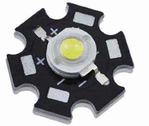
The voltage in the car network is 14 volts. The high-power LED has a forward current of 350 mA and a voltage drop of 3.3 volts. Let's calculate the resistance for a high-power LED as we did above:
U R1 = U E1 - U D1
U R1 = 14V - 3.3V
R1 = U R1 / I
R1 = 10.7V / 350mA
R1 = 31 Ohm
For our example, you need to choose a resistor of at least 31 ohms. The problem is that a high-power LED, as the name itself indicates, has a lot of power and a regular resistor is not enough here. In addition to the appropriate resistance, our resistor must have an appropriate rated power, i.e., the allowable power that is released on the resistor during its operation.
Remember that the primary function of a resistor is to resist current. With resistance, heat will always be released to one degree or another. Too much power can damage the resistor.
We calculate the power using the following formula:
P = 10.7V x 350mA
The power rating of our resistor is 3.7W minimum. Therefore, our standard 0.25W resistors will burn out quickly. In the above example, a 5W resistor needs to be applied, but the best solution use of several 5 W resistors connected in series or in parallel. Why? The reason is that resistors do not dissipate heat well (at least because of their shape), and using multiple resistors will immediately increase the total surface area through which heat is released.
When choosing a resistor for a high-power LED, it is necessary to additionally take into account a significant increase in the temperature of the LED itself, which causes a change in the forward current. Therefore, it is better to take a resistor of higher resistance, which will ensure stable operation of the LED when the forward current increases due to its heating during operation.
But in practice, current stabilizers are used to power high-power LEDs, which will be discussed in subsequent lessons.
A general rule of thumb when selecting the resistor (s) for LEDs is to use a slightly higher resistance than the calculation suggests. It is better to measure the forward current and voltage drop flowing through the LED with a multimeter in order to take into account the real parameters of a particular LED in the calculations.