Instructions
First, we need to figure out what is electricity and how alternating current differs from direct current. The ordered movement of charged particles is called electric current. In a constant electric current, the same amount of charged particles passes through the cross-section of the conductor at the same time intervals. But in alternating current, the number of these particles for the same time intervals is always different.
But now you can transgress directly to the transformation of the variable current to constant, a device called "diode bridge" will help us with this. A diode bridge or bridge circuit is one of the most common devices for rectifying alternating current.
It was originally developed using radio tubes, but was considered complex and expensive decision, instead, a more primitive circuit with a double secondary winding in the transformer supplying the rectifier was used. Now, when semiconductors are very cheap, in most cases it is the bridge circuit that is used. But the use of this circuit does not guarantee 100% rectification. current, therefore, the circuit can be supplemented with a filter on a capacitor, and also, possibly, a choke and a voltage stabilizer. Now, at the output of our circuit, as a result, we get a constant current
To get permanent current, it is enough to take an ordinary battery. The voltage of such a source current and, as a rule, the standard is 1.5 Volts. By connecting several such cells in series, you can get a battery with a voltage proportional to the number of such cells. To obtain permanent current and you can also use a charger from mobile phone(5 V) or car battery (12V). However, if it is necessary to obtain a non-standard voltage, for example, 42 V, then you will have to build homemade rectifier with the simplest power filter.

You will need
- Step-down transformer 220 V. / 42 V.
- Power cord with plug
- Diode Bridge PB-6
- Electrolytic capacitor 2000uF × 60v
- Soldering iron, rosin, solder, connecting wires.
Instructions
Assemble the rectifier according to the diagram shown in the figure:
To properly assemble and use such a device, minimal knowledge of the processes taking place in the device is required. Therefore, carefully read the circuit and the principles of operation of the rectifier. The circuit of the diode bridge, explaining the principle of its operation: During the positive half-cycle (small dotted line) current moves along the upper right shoulder of the bridge to the positive terminal, through the load it enters the left lower shoulder and returns to the network. During negative half cycle (large dash dotted line) current flows on another pair of rectifier bridge diodes. Here Tr. - a transformer, which reduces the voltage from 220 to 42 Volts, galvanically separates high and low voltage. D - diode bridge, rectifies the alternating voltage received from the transformer. Number 1 denotes the primary (network) winding of the transformer, number 2 - the secondary (output) winding of the transformer.
Connect the mains cable with a plug to the primary winding of the transformer. Connect two wires of the secondary winding of the transformer to the two input terminals of the diode bridge. Solder the output of the diode bridge marked "minus" to the negative terminal of the capacitor.
The negative terminal of the capacitor is marked on its body with a light strip with a minus sign. Solder a blue wire to the same terminal. This will be the negative output of the rectifier. Solder the lead of the diode bridge with the plus sign to the second lead of the capacitor together with the red wire. This will be the positive lead of the rectifier. Before switching on, carefully check the correct installation - errors are not allowed here.
Related Videos
The capacitor acts as a power filter, smoothing the ripple remaining after rectification diode bridge alternating current.
To charge the heating battery, a charger is used, which can be purchased in a retail network or made by hand, spending a minimum of money and time.

You will need
- Half liter glass jar, aluminum and lead plate, rubber tube, lid with a hole in the middle.
Instructions
Take a glass or half-liter glass jar, aluminum and lead plates measuring 40x100 mm and a rubber tube 2 cm in diameter. Cut a 2 cm long ring from the rubber tube, pull it over the aluminum plate, to the level of the electrolyte. This is necessary, since during the operation of the rectifier, the electrolyte strongly corrodes aluminum at the very surface of the solution. Rubber protects it from corrosion and thus allows the rectifier to work much longer.
Use sodium bicarbonate (baking soda) as the electrolyte. Take soda at the rate of 5-7 grams. per 100 ml of water. In this rectifier, the positive pole will be aluminum, the negative pole will be lead. When the device is connected to a normal city AC network with a lead plate, through rectifier current will flow. But it will only go in one direction. At this time, there will always be a positive voltage pole on the aluminum plate. If the aluminum plate is connected to the network, then there will be a negative voltage pole on the lead plate. It turns out half-wave rectifier, because an electric current passes through it for only one half-cycle. In the first case, for example, only a positive current will flow through the device.
Full-wave rectifiers are used to fully utilize the voltage. They need to be composed of two or four elements, depending on the current required for charging. And they are connected to both phases of the power supply.When connecting the device to the AC power supply, use fuses. Adjustment of the voltage supplied for charging can be done using a rheostat, which will allow "extinguish" excess voltage in the circuit and, accordingly, create normal conditions for charging the battery.
Related Videos
note
To charge the heating batteries, it is advisable to use a rectifier of 4 elements, since a rectifier with an aluminum plate area of 100 square meters is required to remove the current of one ampere. cm.
Helpful advice
The charging current of the batteries must be 0.1% of its capacity.
Sources:
- Battery charging rectifier
If you decide to make a transformer yourself, then you need to know some things about this device, including how to calculate current v transformer, which will be discussed below.

Instructions
Find out if you did not know before, the maximum current loads and voltage on the secondary winding.
Multiply current maximum load(in amperes) by a factor of 1.5 - you will recognize the winding of the second transformer (in amperes).
Calculate the power consumed by the rectifier from the secondary winding of the transformer. To do this, multiply the secondary voltage by the maximum current that goes through it.
Calculate the power of the transformer. To find out the power, multiply the maximum power on the secondary winding by 1.25.
Calculate the value of the tone on the primary winding. For this, the power received in the last paragraph must be divided by the mains voltage at the primary winding.
Calculate the parameters of the magnetic core area
"Belorussian State University informatics and radioelectronics "
Department of Information Security
« ELECTRIC CONVERTERS »
Inverter- converts direct current to alternating current.
Converter- a DC-to-DC converter, but of a different level (with an intermediate conversion of the input voltage to AC and transformation to the desired level).
The central link is a DC-to-AC converter.
Apply various schemes such devices:
Transistor and electronic tubes;
Constructed on transistors with saturable cores;
Relaxation generators, triggers, multivibrators;
Single-cycle, push-pull and bridge circuits;
Thyristor simple and bridge circuits (in powerful devices).
Simple circuit push-pull thyristor inverter
Figure 1 - a simple circuit of a push-pull thyristor inverter
From T2, control pulses are sent to the thyristor circuit.
From a constant source, voltage is supplied to the input of the circuit. It goes through
to the VD anodes. charges up to double the input voltage. If you now apply pulses to VD2, VD1 immediately closes, recharges, all signs in T1 will change to the opposite and the current will flow through VD2.As can be seen from the operation of the circuit, on the switching capacitance
at the moment of closing the thyristor, a voltage equal to twice the supply voltage acts, which is a disadvantage for the circuit.It is eliminated by the bridge circuit of the thyristor inverter.
Thyristor inverter bridge circuit
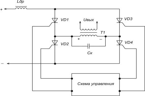
Figure 2 - Bridge circuit of a thyristor inverter
The control circuit opens first VD1 and VD4, and then, when the capacity is charged to
, at this moment, if you open other thyristors, VD1 and VD4 will instantly close.In this circuit, only the power supply voltage acts on the closed thyristors.
Thyristor rectifiers are effective promising inverters. They are used at significant power and are currently used to replace electric machine units that convert DC energy of backup batteries into alternating current in guaranteed power supply devices (UGP) of equipment at communications enterprises.
DC voltage converters
Often when eating electronic devices The power supplies are low-voltage, and significant voltages are required to power the consumption circuits. In this case, they resort to voltage conversion. For this, inverters and converters are used. Used electromagnetic transducers, vibration transducers and static transducers on p / p devices.
Electromagnetic transducers produce a sinusoidal voltage, while semiconductor and vibration transducers produce a rectangular voltage. Currently, there are static converters with an output voltage close to sinusoidal. Disadvantage of an electromagnetic converter: large dimensions and weight. Vibration transducers are low-power and unreliable. Therefore, the greatest application is found for semiconductor converters with small dimensions and weight, high efficiency and operational reliability.
The construction of converters on thyristors and transistors should be associated with the magnitude of the supply voltages, the required power, the nature of the load change.
Transistor voltage converters
They are subdivided by the excitation method into 2 types: self-excitation and power amplification converters.
Transistors can be switched on according to the scheme with OE, OK, ON, but the most widely used are the switching on with OE, since in this case the maximum amplification of transistors in power is realized and the more simply self-excitation conditions are achieved.
Self-excited converters are performed on powerful ones, up to several tens of watts, according to single-cycle and push-pull circuits. The simplest single-ended converter circuit is a feedback relaxation oscillator.


With reverse incl. diode. With direct connection. diode.
When the supply voltage is connected through a resistor, a reference potential is applied to the base of the transistor. The transistor opens and a current flows through the primary winding Wk of the transformer, which causes a magnetic flux in the magnetic circuits of the transistor. The resulting voltage on the winding Wk is transformed in the winding feedback Wb, the connection polarity of which is such that it contributes to the unlocking of the transistor. When the collector current reaches its maximum value: Ik = Ib * h21e, the increase in magnetic flux will stop, the polarity of the voltages on the transformer windings is reversed and an avalanche-like process of transistor locking occurs. The voltage on the secondary winding of the transformer is rectangular.
The polarity of the connection of the rectifier power diode on the secondary winding of the transformer determines the method of transferring energy to the load. The diode opens when the transistor closes, the capacitor is charged, which maintains a constant current in the load.
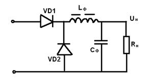
When the diode is switched on directly, the transfer of energy from the power source Uп to the load Rн occurs during the time period tu, when the transistor and the power diode VD1 are open. The choke stores energy W = 0.5 * Lf * In ^ 2 * tu. In this case, the capacitor of the smoothing filter Cf is charged with a rectified voltage up to Uп.
During the pause tp, when the transistor is closed, the current circuit Iн is closed through the choke Lf and the blocking diode VD2, as in a pulse regulator with sequential regulation.
In single-ended converters, the transformer works with bias, to combat which you can use a core with a charge. However, it is not suitable when using torus. transistor. In our case, a blocking capacitor is used, which, during the pause tp, is discharged through the winding W1, reversing the magnetization of the core with the discharge current.
Capacity Cbl. It is selected from the condition that at the maximum filling factor φmax the duration of the pause tp is at least a quarter of the period of the oscillatory circuit L, Cbl.
Such a reverse diode converter provides isolation and protection of the output voltage from noise on the input power rails.
Transistor converters are determined by the following formulas:
Uп = Uп (Iкм / 2Iн-W1 / W2)
tu = Ikm * L1 / Uп
tp = Ikm * L2 / Un * W2
φ = fp * Ikm * L1 / Up = tu / (tu + tp)
The best weight and dimensions have push-pull converters with a step-down transformer.
Transformers are made on a magnetic circuit with a rectangular hysteresis loop. Positive feedback is also used here. The generator works as follows. When the supply voltage Uп is turned on, due to the non-identical parameters, one of the transistors, for example VT1, begins to open and its collector current increases. The OS windings Wb are connected so that the EMF induced in them completely opens the transistor VT1 and closes the transistor VT2.
Switching of transistors begins at the moment of transistor saturation. As a result, transf. The voltages decrease to zero and then reverse their polarity.
Now a negative voltage is supplied to the base of the previously opened transistor VT1, and a positive voltage is supplied to the base of the previously closed transistor VT2 and it begins to open. This regenerative process of forming the output voltage front is very fast. In the future, the processes in the scheme are repeated.
 The switching frequency depends on the value of the supply voltage, the parameters of the transformer and transistors and is calculated by the formula: fп = ((Uп-Uke us) * 10000) / 4 * B * s * Wк * Sc * Kc.
 This mode is more economical than switching due to the collector current limit and the operation of the converter is more stable.
Such converters are used as master oscillators for power amplifiers and as stand-alone low-power power supplies. Main advantages: simplicity of the circuit, as well as insensitivity to short circuit in the load circuit.
The disadvantage of a converter with a saturable core is the presence of collector current surges at the moment of switching the transistors, which increases the losses in the converter.
The voltage across the closed transistor can reach the value:
Uкэm = (2,2: 2,4) Uпmax
two voltages are the sum of Uп + EMF on the idle winding, in addition, voltage surges during switching are taken into account. To reduce the latter, shunt diodes are sometimes included in the circuit.
When converting large capacities most widespread received converters using a power amplifier. Self-excited converters can be used as a master oscillator. The use of such converters is advisable if it is necessary to ensure the constancy of the frequency and voltage at the output, as well as the constancy of the shape of the AC voltage curve when the load of the converter changes.
In the case of a high input voltage, bridge power amplifiers are used.
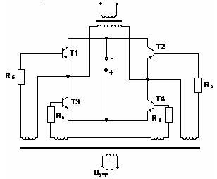 Suppose transistors T1, T2 work simultaneously during the first half cycle. In the second T2, T3. The supply voltage is applied to the primary winding of the transistor, its polarity changes every half cycle. The voltage across the closed transistor is equal to the voltage of the power supply. The output transistor operates in an unsaturated mode, it is made from a material with a non-rectangular hysteresis loop.
 Thyristor converters
Thyristors, unlike transistors, have one-way control. To block thyristors in converter circuits, reactive elements are used mainly in the form of switching capacitors.
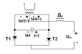 When the first thyristor is unlocked, the capacitance is charged to a voltage of 2Up. When the second thyristor is unlocked, the capacitor voltage is applied in the opposite direction to the first transistor; under its action, it is locked. The capacitor is recharged, and the voltage on its windings and on the primary winding of the thyristor changes sign (potentials are shown in the diagram in brackets). In the next half-cycle, thyristor T1 is unlocked again and the process is repeated.
 To ensure the locking of the thyristors, it is necessary that the energy of the switching capacitor be sufficient so that in the process of recharging the reverse voltage across the thyristors drops rather slowly and would have time to ensure the restoration of their locking properties.
The disadvantage of such an inverter is the strong dependence of the output voltage on the load current.

To reduce the influence of the nature and magnitude of the load on the shape and magnitude of the output voltage, circuits with reverse diodes are used, which in turn are necessary to return the reactive energy accumulated in the inductive load and reactive switching elements in the converter power supply.
Power supply with transformerless input
A feature of such sources is the use of the process of converting the input voltage using high frequency.
The absence of a power transistor at the input and the use of transistors at an increased frequency significantly improves the weight and size characteristics.
The functional diagram of the IPBV based on an adjustable converter is as follows:

HFF - prevents the penetration of interference from the IPBV into the input circuits and vice versa.
VU - rectifier device,
SF - smoothing filter;
RP - adjustable converter;
ЗГ - synchronizing master oscillator;
GPN - sawtooth voltage generator.
The operation of the IPBV with stabilization of the input voltage using PWM is easy to imagine by examining the voltage diagrams in individual sections of the circuit.

In order to simplify the adjustment, the converter is usually built according to a single-cycle scheme with the provision of recuperation of a part of the energy accumulated in the reactive elements to the input voltage source. At the output of the converter at voltages of 5 - 10V, a rectifier with a midpoint is installed. In order to reduce the switching time of power transistors at their inputs, circuits are used that provide a significant excess of the blocking voltage in relation to the negative one.
LITERATURE
1. Ivanov-Tsyganov A.I. Electrical devices radio systems: Textbook. - Ed. 3rd, rev. and additional-Mn: graduate School, 200
2. Alekseev OV, Kitaev VE, Shikhin A.Ya. Electrical devices / Ed. A.Ya. Shikhina: Textbook. - M .: Energoizdat, 200–336 p.
3. Berezin O.K., Kostikov V.G., Shakhnov V.A. power supplies for electronic equipment. - M .: Tri L, 2000 .-- 400 p.
4. Shustov M.A. Practical circuitry. Power supplies and stabilizers. Book. 2. - M .: Altex a, 2002. –191 p.
Power outages in our homes, alas, are becoming a tradition. Does the child have to do homework by candlelight? Or just an interesting film on TV, that would be to finish watching. All of this is fixable if you have a car battery. To it you can assemble a device called a DC-to-AC converter (or, in Western terminology, a DC-AC converter).
Figures 1 and 2 show two main circuits of such converters. The circuit in Fig. 1 uses four powerful transistors VT1 ... VT4, operating in key mode... In one half-cycle of voltage 50 Hz, transistors VT1 and VT4 are open. The current from the GB1 battery flows through the transistor VT1, the primary winding of the transformer T1 (from left to right according to the diagram) and the transistor VT4. In the second half-cycle, transistors VT2 and VT3 are open, the current from the GB1 battery goes through the transistor VT3, the primary winding of the transformer TV1 (from right to left according to the diagram) and the transistor VT2. As a result, the current in the winding of the transformer TV1 turns out to be variable, and in the secondary winding the voltage rises to 220 6. When using a 12-point battery, the coefficient K = 220/12 = 18.3.
A pulse generator with a frequency of 50 Hz can be built on transistors, logic microcircuits and any other element base Figure 1 shows a pulse generator based on an integral timer KR1006VI1 (DA1 microcircuit). From the DA1 output, 50 Hz pulses pass through two inverters on transistors VT7, VT8. From the first of them, the pulses are fed through the VT5 current amplifier to the VT2, VT3 pair, from the second - through the VT6 current amplifier to the VT1, VT4 pair. If you use transistors with a high current transfer ratio ("superbet") as VT1 ... VT4, for example, such as KT827B or powerful field-effect transistors, for example, KP912A, then the current amplifiers VT5, VT6 can be omitted.
In the circuit in Fig. 2, only two powerful transistors VT1 and VT2 are used, but the primary winding of the transformer has twice as many turns and a midpoint. The pulse generator in this circuit is the same, the bases of the transistors VT1 and VT2 are connected to points A and B of the pulse generator circuit in Fig. 1.
The operating time of the inverter is determined by the capacity of the battery and the power of the load. If you allow the battery to discharge at 80% (such a discharge is allowed lead-acid batteries), then the expression for the operating time of the converter is:
T (h) = (0.7WU) / P, where W is the battery capacity, Ah; U is the nominal voltage of the battery, V; Р - load power, W. This expression also takes into account the efficiency of the converter, which is 0.85 ... 0.9.


Then, for example, when using a car battery with a capacity of 55 Ah with a nominal voltage of 12 V with a load on a 40 W incandescent bulb, the operating time will be 10 ... 12 hours, and with a load on a 150 W television receiver, 2.5-3 hours.
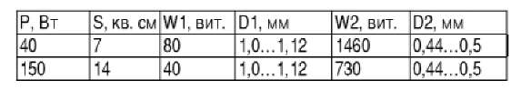
We give the data of the transformer T1 for two cases: for a maximum load of 40 W and for a maximum load of 150 W.
In the table: S - cross-sectional area of the magnetic circuit; W1, W2 - the number of turns of the primary and secondary windings; D1, D2 - diameters of wires of primary and secondary windings.
You can use a ready-made power transformer, do not touch the mains winding, but wind up the primary winding. In this case, after winding, you need to turn on the mains winding and make sure that the voltage on the primary winding is 12 V.
If you use KT819A as powerful transistors VT1 ... VT4 in the circuit in Fig. 1 or VT1, VT2 in the circuit in Fig. 2, then you should remember the following. The maximum operating current of these transistors is 15 A, therefore, if you count on a converter power of more than 150 W, then you must install either transistors with a maximum current of more than 15 A (for example, KT879A), or connect two transistors in parallel. With a maximum operating current of 15 A, the dissipation power for each transistor will be approximately 5 W, while without a radiator, the maximum power dissipation is 3 W. Therefore, on these transistors, it is necessary to install small radiators in the form of a metal plate with an area of 15-20 cm.
The output voltage of the converter has the form of bipolar impulses with an amplitude of 220 V. This voltage is quite suitable for powering various radio equipment, not to mention electric bulbs. However, single-phase electric motors with this form of voltage do not work well. Therefore, you should not include a vacuum cleaner or tape recorder in such a converter. A way out of the situation can be found by winding an additional winding on the transformer T1 and loading it on the capacitor Cp (shown by a dotted line in Fig. 2). This capacitor is chosen such that it forms a circuit tuned to a frequency of 50 Hz. With a converter power of 150 W, the capacitance of such a capacitor can be calculated by the formula C = 0.25 / U2, where U is the voltage generated on the additional winding, for example, at U = 100 V, C = 25 μF. In this case, the capacitor must operate at an alternating voltage (you can use metal-paper capacitors K42U or similar) and have operating voltage not less than 2U. Such a circuit takes up part of the power of the converter. This part of the power depends on the quality factor of the capacitor. So, for metal-paper capacitors, the dielectric loss tangent is 0.02 ... 0.05, so the efficiency of the converter decreases by about 2 ... 5%.
To avoid damage battery the converter does not interfere with equipping with a discharge alarm. A simple diagram of such a signaling device is shown in Fig. 3. Transistor VT1 is a threshold element. While the battery voltage is normal, the transistor VT1 is open and the voltage on its collector is below the threshold voltage of the DD1.1 microcircuit, therefore the audio frequency signal generator on this microcircuit does not work. When the battery voltage drops to a critical value, the transistor VT1 is locked (the locking point is set variable resistor R2), the generator on the DD1 microcircuit starts to work and the acoustic element HA1 begins to "beep". Instead of a piezoelectric element, you can use a low-power dynamic loudspeaker.
The battery needs to be charged after using the inverter. For charger you can use the same transformer T1, but the number of turns in the primary winding is not enough, since it is designed for 12 V, and you need at least 17 V. Therefore, in the manufacture of the transformer, an additional winding for the charger should be provided. Naturally, when charging the battery, the converter circuit must be turned off.
V. D. Panchenko, Kiev
Page 1
The conversion of direct current into alternating current in a dynamic capacitor is carried out due to the periodically changing capacitance of the capacitor when one of the plates vibrates.
Converting DC to AC is called inverting, and a device that performs this function is called an inverter.
Converting DC to AC and modulating AC signals. For DC voltage amplification, amplifiers with direct galvanic coupling between stages are usually used. A significant disadvantage of all DC amplifiers is zero drift. The presence of a zero drift and the difficulty of directly amplifying small direct voltages were the reason for the emergence of a number of amplifier circuits with the conversion of direct voltage to alternating voltage and amplifying the latter using an alternating current amplifier. Mechanical, microphone, electronic and other devices are used as converters.
Conversion of direct current to alternating current is carried out by periodically interrupting the load supply circuit. If the output voltage level of the inverter is different from that of the DC input voltage, the load is connected through the transformer.
DC to AC conversion and reverse conversion.
Conversion of direct current to alternating current (inversion) can be carried out using electric valves, the conductivity of which can be controlled. Thyristors are used for this purpose. As shown, the phase-controlled rectifier and the mains-driven inverter (inverter, the current frequency of which corresponds to the mains frequency and P0 Rin) operate in the same way and any of these modes can be implemented in the same circuit. When operating as a rectifier, the device transfers energy to a DC load. When it works as an inverter, a constant voltage source is needed to create a current in the device and transfer power to the AC side, the inverter mode occurs at 90 hours - 180 el. The grid-driven (non-autonomous) inverter is used for rheostat testing of energy recovery locomotives. Such attitudes are becoming more widespread about every year.
The conversion of direct current into alternating current is performed by a capacitor, the capacitance of which changes periodically (for example.
1.3. AC conversion
to constant and constant to variable
Electricity is generated in power plants by synchronous generators, i.e. alternating current generators, which can be conveniently converted by transformers and transmitted over long distances. Meanwhile, there is a number technological processes requiring direct current: electrolysis, battery charging, etc. Therefore, it is often necessary to convert alternating current into direct current and vice versa.

Widespread at the beginning of the XX century. electrical machine converters (single-armature converters and motor-generator sets) have given way to more compact and quiet semiconductor rectifiers. Due to the high

Rice. 1.12. Single-phase push-pull rectifier
operating indicators and small dimensions of semiconductor rectifiers, there is a tendency to replace DC generators with synchronous generators having a semiconductor rectifier at the output. Thus, new classes of machines appeared - transformers and synchronous ones - constantly working with rectifiers. However, the operation of an electric machine on a rectifier has features that must be taken into account when designing these machines and analyzing the processes occurring in them.
AC conversion v constant is produced using semiconductor valves with one-way conductivity. In fig. 1.12 and 1.13 show the most common rectifier circuits: single-phase (Figure 1.12, a) and three-phase (Figure 1.13, a) and voltage and current curves (Figure 1.12.5. v, rice. 1.13.6, v respectively). Current can pass through semiconductor valves (diodes) only when a positive potential is applied to the anode (in the direction of the apex of the triangle in Fig. 1.12, a), and therefore the voltage across the load is pulsating.

Rice. 1.13. Three Phase Bridge Rectifier
With single-phase rectification, the voltage ripple at the ^ -load is very significant, and the frequency of the variable component is 2 times higher than the frequency of the alternating current (Fig. 1.12, b). With three-phase bridge rectification, the circuit is six-cycle and the voltage ripple is small - less than 6% of the DC component (Fig.1.13, b).
The current in the load circuit is usually smoothed more than the voltage, since the load circuit often contains inductance, which represents high resistance for the AC component of the current and small for the DC component.
If we count the current in the load /<* полностью сглаженным, то по обмоткам трансформатора проходит ток, имеющий вид прямоугольников (рис. 1.12,6 и 1.13, v), containing higher harmonics that increase the heating of the windings. In addition, when using rectification circuits with a zero point, there is a constant component of the current in the windings (Fig. 1.12.6). Because of this, the effective value of the current rises sharply and measures must be taken against the creation of a permanent bias of the rod. To prevent this phenomenon, for example, in single-phase transformers, either armored structure (Fig. 1.14), or on each rod all the windings of the transformer are placed, dividing them in half.
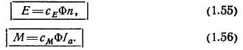
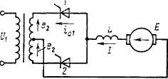
A great influence on the operation of the rectifier (Fig. 1.15, o) is provided by current switching - the process of transition from one valve to another.
Due to the presence of inductances in the current-conducting circuit and the inductance caused by the leakage fluxes of the transformer, the current from one valve does not pass to another immediately, but during the switching period Г к, which corresponds to the switching angle at(Figure 1.15, b).
For simplicity, let's assume that the load current Id perfectly smoothed. Then the sum of the currents through the first and second valves i a \ and iai unchanged during the commutation:

Rice. 1.14. Schematic drawing of an armored transformer
At the moment of the beginning of switching, when the value of the EMF passes through zero and changes sign, the transformer winding becomes short-circuited and for its circuit one can write the equation
During switching, the voltage across the load SLg = 0.5 (e 2a + + e 2 b) and in a single-phase rectifier is zero (Fig.1.15, b). Consequently, due to commutation, the rectified voltage decreases and its ripple increases. Since the switching angle y is the larger, the greater the load current I d and inductive reactance x a, to improve the quality of the rectifier, it is desirable that the machine supplying it has a small inductive resistance. In the transformer x a equal to the inductive resistance due to leakage fluxes, and is determined from the short-circuit experience In a synchronous generator
where Ha" and x q "- super-transient inductances along the longitudinal and transverse axes, respectively, taking into account the presence of current in the damper winding.
Thus, synchronous generators designed to operate on a rectifier must be designed to operate with non-sinusoidal current and have a damper winding.

The power factor of a generator driven by an unregulated rectifier is
Rice. 1.16. Single phase inverter circuit
where v «0.9 - distortion coefficient; > ф «0,5у - current shift angle relative to the first voltage harmonic.
Converting DC to AC produced with the help of inverters that use controlled valves: transistors, thyristors, etc.
The diagram of a single-phase inverter is shown in Fig. 1.16. The inverter valves are turned on alternately every half-cycle so that the direction of the current in the secondary winding of the transformer is opposite to the direction of the EMF in this winding, that is, so that energy is transferred from the direct current source to the alternating current network.
Inverters have a comparatively complex system automatic control, which leads to an increase in their cost and a decrease in reliability compared to uncontrolled rectifiers.
In addition, the mode may appear in the inverter. through combustion, when the current in the winding is in phase with its EMF. This mode is possible either in the event of a malfunction in the control system, or when the switching angle is too large. During through burning, the current usually rises to an unacceptable value and usually the semiconductor valves fail. A large number of elements in the control system and the possibility of an emergency mode of through combustion make the reliability of inverters much lower than that of uncontrolled rectifiers: the MTBF is reduced by 50 ... 100 times.
The idea of supplying induction and synchronous motors from inverters is promising. By changing the frequency of switching on the valves, it is possible to change the frequency of the voltage at the terminals of the stator of the motor and thereby economically (without resistances) regulate the angular velocity. This method of speed control is called frequency control. However, the low reliability of systems with inverters - frequency converters prevents their widespread use.
At present, frequency regulation of speed is applied only in special conditions where DC motors immersed in liquid cannot work: motors of ships, oil pipelines, motors of ball mills, etc.

Rice. 1.17. DC machine device
There are experimental samples with frequency control in crane and traction electrical equipment.
The DC machine has a kind of collector converter, which is a rectifier in generator mode, and a frequency converter in motor mode.
The design of a DC machine is similar to the design of an inverted synchronous machine, in which the armature winding is on the rotor and the magnetic poles are stationary. When the armature (rotor) rotates, an EMF is induced in the winding conductors, directed as shown in the cross-section of Fig. 1.17, a.
In conductors located on one side of the line of symmetry separating the poles, the EMF is always directed in one direction, regardless of the angular velocity. When rotating, some conductors go under the other pole, other conductors come in their place, and in space, under the pole of one polarity, the picture is almost motionless, only some conductors are replaced by others. Therefore, it is possible to obtain a practically unchanged EMF from this part of the winding.
A constant EMF is obtained using a sliding contact between the winding and an external electrical circuit.
Conductors are connected in turns with a pitch usht, as in AC machines, and then the turns are connected in series one after the other, a closed winding is formed.
In half of the winding (in a two-pole machine), an EMF of one sign is induced, and in the other, the opposite, as shown in the equivalent winding circuit (Fig.1.17, b). Along the contour of the winding, the EMF in its parts is directed oppositely and is mutually balanced. As a consequence, at idle generator, that is, in the absence of an external load, the current does not pass through the armature winding.
The outer chain is connected to the armature via brushes mounted on geometric neutral.
To improve contact, the brushes are made in the form of rectangular graphite bars, and they slide over the surface of the collector, which is assembled from copper plates isolated from each other.
In large machines, the beginning and end of each turn are attached to manifold plates; small plate machines
less than turns, and therefore a part of the winding of several turns is soldered between the two plates - a section.
Under load, a current flows through the armature conductors, the direction of which is determined by the direction of the EMF.
Due to the fact that the load current is constant, in the turns of the armature winding, the current has a shape close to rectangular (Fig. 1.18, a).
When a coil passes from one parallel branch to another, it is short-circuited with a brush for a time called switching period(Fig. 1.18, b)
T K = bJv KOn,(1.66)
where B u- brush width; and K ol is the linear velocity of a point located on the surface of the reservoir.
In the simplest case, when the brush is narrower than the collector plate, for the section closed by the brush (Fig. 1.18,0),
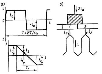
Rice. 1.18. Switching current diagrams
where iiRi = AUi and i 2 R2 = AU 2- voltage drop in the brush contact, respectively, with the first and second collector plates; R c- active resistance of the section; L pe3 - the resulting inductance of the section; e to- EMF from an external field. Neglecting iR c due to the smallness R c, get
The resulting basic commutation equation(1.68) coincides with the commutation equation in the rectifier(1.61). The solution of this equation is easy to obtain, assuming that A £ A-A £ / 2 «0,
So that when the first plate leaves from under the brush, no current break occurs, at the time t = T K the current through the first plate should be equal to zero: 11 (Гк) = 0 = 21 а - |
This condition for sparkless switching is reduced to the fact that, in all modes, the switching angle at was unchanged:
y = * T K = 2vJ> JD a v Koll = 2b "jD a, (1.71)
where D a- anchor diameter; v a - linear speed of a point on the surface of the anchor; B "u = bshO a / O KO l- the width of the brush, reduced to the diameter of the armature.
To fulfill this condition, EMF in the EMF switching zone e to created by special additional poles, the winding of which is connected in series to the armature circuit, and their magnetic circuit is made unsaturated.
The switching process in rectifiers, inverters and DC machines is similar. In both cases, the process of changing the current during the switching period is determined by the value and shape of the EMF in a short-circuited circuit. Therefore, the collector cannot be likened to a mechanical rectifier, as is sometimes done.
The presence of a collector also introduces its own peculiarities: the design of the machine becomes more complicated and operation becomes more expensive. However, these disadvantages of electric machines are atoned for by their main advantage: in the motor mode, accidental switching faults usually lead to a slight burnout of the collector and brushes, and not to emergency mode. rollover, as in inverters.
As a result, the reliability of the DC collector machine is much higher than the reliability of the "induction motor-frequency converter" system, its efficiency is 3 ... 5% higher, the machine is much cheaper, has smaller dimensions and weight.
These advantages make us give preference to a DC machine, limiting the use of an asynchronous motor with frequency control to the narrow scope of specific devices (motors operating in a liquid, etc.).