Powerful voltage stabilizers with current protection
To power some radio devices, a power supply with increased requirements for the level of minimum output ripple and voltage stability is required. To provide them, the power supply has to be performed on discrete elements.
Shown in fig. 4.7 the circuit is universal and on its basis it is possible to make a high-quality power supply for any voltage and current in the load.
The power supply is assembled on a widely used dual operational amplifier (KR140UD20A) and one power transistor VT1. In this case, the circuit has current protection, which can be adjusted over a wide range.
The operational amplifier DA1.1 has a voltage regulator, and DA1.2 is used to provide current protection. Chips DA2, DA3 stabilize the power supply of the control circuit assembled on DA1, which improves the parameters of the power supply.
The voltage stabilization circuit works as follows. Voltage feedback is removed from the source output (X2). This signal is compared with the reference voltage coming from the zener diode VD1. A mismatch signal is applied to the input of the op-amp (the difference between these voltages), which is amplified and fed through R10-R11 to control the transistor VT1. Thus, the output voltage is maintained at a given level with an accuracy determined by the gain of the op-amp DA1.1.
The desired output voltage is set by resistor R5.
In order for the power supply to be able to set the output voltage to more than 15 V, the common wire for the control circuit is connected to the "+" (X1) terminal. In this case, to fully open the power transistor (VT1), a small voltage is required at the output of the op-amp (on the basis of VT1, Ube = + 1.2 V).
Such a construction of the circuit allows you to make power supplies for any voltage, limited only by the allowable collector-emitter voltage (Uke) for a specific type of power transistor (for KT827A, the maximum Uke = 80 V).
In this circuit, the power transistor is composite and therefore can have a gain in the range of 750 ... 1700, which allows you to control it with a small current - directly from the output of the op-amp DA1.1. This reduces the number of required elements and simplifies the circuit.
The current protection circuit is assembled on the op-amp DA1.2. When current flows through the load, voltage is generated across resistor R12. It is applied through the resistor R6 to the connection point R4-R8, where it is compared with the reference level. As long as this difference is negative (which depends on the current in the load and the resistance value of the resistor R12) - this part of the circuit does not affect the operation of the voltage regulator.
As soon as the voltage at the specified point becomes positive, a negative voltage will appear at the output of the op-amp DA1.2, which, through the VD12 diode, will reduce the voltage at the base of the power transistor VT1, limiting the output current. The level of output current limitation is adjusted using resistor R6.
Diodes connected in parallel at the inputs of operational amplifiers (VD3...VD7) protect the microcircuit from damage if it is turned on without feedback through the transistor VT1 or if the power transistor is damaged. In operating mode, the voltage at the inputs of the op-amp is close to zero and the diodes do not affect the operation of the device.
The capacitor SZ installed in the negative feedback circuit limits the band of amplified frequencies, which increases the stability of the circuit, preventing self-excitation.
A similar power supply circuit can be performed on a transistor with a different conductivity KT825A (Fig. 4.8).
When using the elements indicated in the diagrams, these power supplies allow the output to receive a stabilized voltage of up to 50 V at a current of 1 ... 5 A.
The technical parameters of a stabilized power supply are obtained no worse than those indicated for a circuit similar in principle to operation, shown in fig. 4.10.
The power transistor is mounted on a radiator, the area of which depends on the current in the load and the voltage 11ke. For normal operation of the stabilizer, this voltage must be at least 3 V.
When assembling the circuit, the following parts were used: tuned resistors R5 and R6 of the SPZ-19a type; fixed resistors R12 of the C5-16MV type for a power of at least 5 W (the power depends on the current in the load), the rest are from the MLT and C2-23 series of the corresponding power. Capacitors C1, C2, SZ type K10-17, oxide polar capacitors C4 ... C9 type K50-35 (K50-32).
The chip of the dual operational amplifier DA1 can be replaced by an imported analog tsA747 or two 140UD7 chips; voltage regulators: DA2 on 78L15, DA3 on 79L15.
The parameters of the network transformer T1 depend on the required power supplied to the load. For voltage up to 30 V and current 3 A, you can use the same one as in the circuit in Fig. 4.10. In the secondary winding of the transformer, after rectification on the capacitor C6, a voltage of 3 ... 5 V must be provided more than is required to be obtained at the output of the stabilizer.
In conclusion, it can be noted that if the power supply is supposed to be used in a wide temperature range(-60 ... + 100 ° С), then in order to obtain good specifications additional measures need to be taken. These include improving the stability of reference voltages. This can be done by choosing zener diodes VD1, VD2 with a minimum TKN, as well as stabilizing the current through them. Usually, current stabilization through a zener diode is performed using field effect transistor or by using an additional microcircuit operating in the current stabilization mode through a zener diode, fig. 4.9. In addition, zener diodes provide the best voltage thermal stability at a certain point in their characteristic. In the passport for precision zener diodes, this current value is usually indicated and it is it that must be set with tuned resistors when setting
node of the reference voltage source, for which a milliammeter is temporarily included in the zener diode circuit. . ",
We offer conventional and high-precision stabilizing devices for adjusting low-quality input power from a popular manufacturer in Russia - ETK Energia. In stock current section our specialized online store presents the most simple apparatus relay type with the possibility of wall or floor installation. The performance of the single-phase electrical equipment recommended for ordering occurs automatically. All of them successfully protect against emergencies in a variable network 220V, working in wide range network surges and drawdowns. You can buy a simple voltage stabilizer with current protection in Moscow, St. Petersburg and the region. The accuracy of the brand Energia ASN is ±6%, and the universal series Energy Voltron is ±10%. These proven 1-phase electrical appliances have latest system microprocessor control, which ensures the operation of all models for 1, 2, 3, 5, 8, 10, 15, 20, 30 kW Russian production in a very economical energy-saving mode. Majority automatic devices ideally adapted for round-the-clock operation in houses, apartments, cottages, as well as modern office and industrial premises.
 Single-phase simple voltage stabilizers with current protection, dangerous overloads, and short circuit in a 220 Volt household network, regardless of the selected line from the current catalog, they have a minimum noise level, which allows you not to disturb the favorable environment in everyday life or office space. Selling high performance domestic equipment There are also special models for gas boiler- Energy ARS with protection against electromagnetic and impulse interference. On sale there are simple and with a reinforced case frost-resistant devices of high and low power. You can buy a simple voltage stabilizer with current protection in Moscow, St. Petersburg from us at affordable price. Enhanced Security household appliances during continuous operation and the mains single-phase 220V equipment is qualitatively supported by premium multi-level protection. All certified brands from the current Russian assembly catalog Energia and Voltron are developed using an additional built-in self-diagnostic unit, which increases the reliability of home, country and office connected devices. Warranty 1 year. It is very convenient to track information in the 220V electrical network by the presence of a digital display on the main panel.
The current stabilizer for LEDs is used in many fixtures. Like all diodes, LEDs have a non-linear volt-ampere dependence. What does it mean? When the voltage rises, the current slowly begins to gain power. And only when the threshold value is reached, the brightness of the LED becomes saturated. However, if the current does not stop growing, the lamp may burn out.
The correct operation of the LED can only be ensured by a stabilizer. This protection is also necessary because of the variation in LED voltage thresholds. When connected via parallel circuit light bulbs can simply simply burn out, as they have to pass an amount of current that is unacceptable for them.
Types of stabilizing devices
According to the method of limiting the current strength, devices of a linear and pulse type are distinguished.
Since the voltage across the LED is a constant value, current regulators are often considered LED power regulators. In fact, the latter is directly proportional to the change in voltage, which is typical for a linear relationship.
The linear regulator heats up the more, the more voltage is applied to it. This is his main shortcoming. The advantages of this design are due to:
- lack of electromagnetic interference;
- simplicity;
- low cost.
More economical devices are stabilizers based on pulse converter. In this case, power is pumped in portions - as needed for the consumer.
Line device diagrams
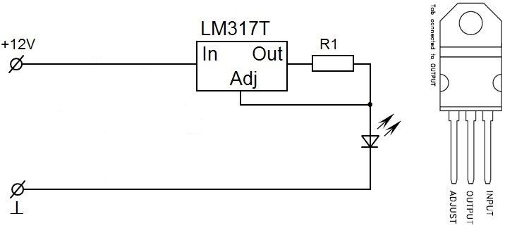
The most the simplest circuit stabilizer is a circuit based on LM317 for LED. The latter are an analogue of a zener diode with a certain operating current that it can pass. Given the low current strength, you can assemble a simple device yourself. The simplest driver LED lamps and tapes are collected in this way.
The LM317 chip has been a hit with beginner radio amateurs for decades due to its simplicity and reliability. Based on it, you can assemble an adjustable power supply, led driver and other BP. This will require several external radio components, the module works immediately, no settings are required.
The LM317 integrated stabilizer, like no other, is suitable for creating simple regulated power supplies, for electronic devices with different characteristics, both with adjustable output voltage and with given load parameters.
The main purpose is the stabilization of the given parameters. The adjustment takes place in a linear way, in contrast to pulse converters.
LM317 are produced in monolithic cases, made in several variations. The most common model TO-220 marked LM317T.
Each output of the microcircuit has its own purpose:
- ADJUST. Input for output voltage regulation.
- OUTPUT. Input for generating the output voltage.
- INPUT. Input for supplying voltage.
Technical indicators of the stabilizer:
- The output voltage is within 1.2–37 V.
- Overload and short circuit protection.
- Output voltage error 0.1%.
- Switching circuit with adjustable output voltage.
Power dissipation and device input voltage
The maximum “bar” of the input voltage should be no more than the specified one, and the minimum one should be 2 V higher than the desired output voltage.
The microcircuit is designed for stable operation at a maximum current of up to 1.5 A. This value will be lower if a good heat sink is not used. The maximum allowable power dissipation without the latter is approximately 1.5 W at a temperature environment no more than 30 0 C.
When installing a microcircuit, it is required to isolate the case from the radiator, for example, using a mica gasket. Also, efficient heat dissipation is achieved through the use of heat-conducting paste.
Short description
Briefly describe the advantages of the LM317 electronic module used in current stabilizers as follows:
- brightness luminous flux provided with output voltage range 1, - 37 V;
- output indicators of the module do not depend on the frequency of rotation of the motor shaft;
- maintaining the output current up to 1.5 A allows you to connect several electrical receivers;
- fluctuation error of output parameters is 0.1% of the nominal value, which is a guarantee of high stability;
- there is a protection function for limiting current and cascading shutdown in case of overheating;
- the chip package replaces the ground, so when external fastening the number of installation cables is reduced.
Switching schemes
Undoubtedly, in the simplest way current limit for LED lamps will become series connection additional resistor. But this tool is only suitable for low-power LEDs.
1. The simplest stabilized power supply
To make a current stabilizer you will need:
Chip LM317;
Resistor;
Mounting aids.
We assemble the model according to the scheme below:
The module can be used in schemes of different chargers or regulated information security.
2. Power supply on the integral stabilizer
This option is more practical. LM317 limits the current consumption, which is set by the resistor R.
Remember that the maximum current you need to drive the LM317 is 1.5A with a good heatsink.
3. Scheme of a stabilizer with an adjustable power supply
Below is a circuit with a regulated output voltage of 1.2-30V / 1.5A.
The alternating current is converted to direct current by a bridge rectifier (BR1). Capacitor C1 filters the ripple current, C3 improves the transient response. This means that the voltage regulator can work perfectly under DC on the low frequencies. The output voltage is adjusted by the P1 slider from 1.2 volts to 30 V. The output current is about 1.5 A.
The selection of resistors at face value for the stabilizer must be carried out according to an accurate calculation with tolerance(small). However, arbitrary placement of resistors on the circuit board is allowed, but it is advisable to place them away from the LM317 heatsink for better stability.
Application area
The LM317 chip is an excellent option for use in the stabilization mode of the main technical indicators. It is characterized by simplicity in execution, inexpensive cost and excellent operational characteristics. The only downside is that the voltage threshold is only 3V. The TO220 style case is one of the most affordable models that dissipates heat fairly well.
The microcircuit is applicable in devices:
- current stabilizer for LED (including LED strips);
- Adjustable .
The stabilizing circuit based on the LM317 is simple, cheap, and at the same time reliable.
To power some radio devices, a power supply with increased requirements for the level of minimum output ripple and voltage stability is required. To provide them, the power supply has to be performed on discrete elements.
Shown in fig. 4.7 the circuit is universal and on its basis it is possible to make a high-quality power supply for any voltage and current in the load.
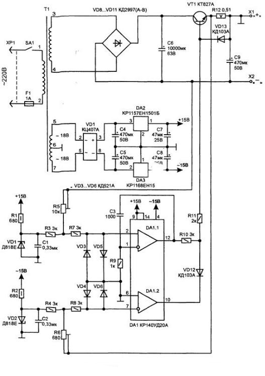
Rice. 4.7. Wiring diagram power supply
The power supply is assembled on a widely used dual operational amplifier (KR140UD20A) and one power transistor VT1. In this case, the circuit has current protection, which can be adjusted over a wide range.
A voltage regulator is made on the DA1.1 operational amplifier, and DA1.2 is used to provide current protection. Chips DA2, DA3 stabilize the power supply of the control circuit assembled on DA1, which improves the parameters of the power supply.
The voltage stabilization circuit works as follows. Voltage feedback is removed from the source output (X2). This signal is compared with the reference voltage coming from the zener diode VD1. A mismatch signal (the difference between these voltages) is supplied to the input of the op-amp, which is amplified and fed through R10-R11 to control the transistor VT1. Thus, the output voltage is maintained at a given level with an accuracy determined by the gain of the op-amp DA1.1.
The desired output voltage is set by resistor R5.
In order for the power supply to be able to set the output voltage to more than 15 V, the common wire for the control circuit is connected to the "+" (X1) terminal. In this case, to fully open the power transistor (VT1), a small voltage is required at the output of the op-amp (based on VT1, Ube = + 1.2 V).
Such a construction of the circuit allows you to make power supplies for any voltage, limited only by the allowable collector-emitter voltage (Uke) for a specific type of power transistor (for KT827A, the maximum Uke = 80 V).
In this circuit, the power transistor is composite and therefore can have a gain in the range of 750 ... 1700, which allows you to control it with a small current - directly from the output of the op-amp DA1.1. This reduces the number of required elements and simplifies the circuit.
The current protection circuit is assembled on the op-amp DA1.2. When current flows through the load, voltage is generated across resistor R12. It is applied through the resistor R6 to the connection point R4-R8, where it is compared with the reference level. As long as this difference is negative (which depends on the current in the load and the resistance value of the resistor R12) - this part of the circuit does not affect the operation of the voltage regulator.
As soon as the voltage at the specified point becomes positive, a negative voltage will appear at the output of the op-amp DA1.2, which, through the VD12 diode, will reduce the voltage at the base of the power transistor VT1, limiting the output current. The level of output current limitation is adjusted using resistor R6.
Diodes connected in parallel at the inputs of operational amplifiers (VD3 ... VD7) protect the microcircuit from damage if it is turned on without feedback through the VT1 transistor or if the power transistor is damaged. In operating mode, the voltage at the inputs of the op-amp is close to zero and the diodes do not affect the operation of the device.
The capacitor C3 installed in the negative feedback circuit limits the band of amplified frequencies, which increases the stability of the circuit, preventing self-excitation.
A similar power supply circuit can be performed on a transistor with a different conductivity KT825A (Fig. 4.8).
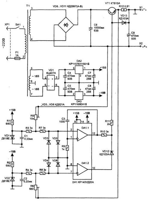
Rice. 4.8 The second version of the power supply circuit
When using the elements indicated in the diagrams, these power supplies allow you to obtain a stabilized voltage of up to 50 V at a current of 1.5 A at the output.
The technical parameters of a stabilized power supply are obtained no worse than those indicated for a circuit similar in principle to operation, shown in fig. 4.10.


Rice. 4.10. Wiring diagram
The power transistor is mounted on a radiator, the area of \u200b\u200bwhich depends on the current in the load and the voltage Uke. For normal operation of the stabilizer, this voltage must be at least 3 V.
When assembling the circuit, the following parts were used: tuning resistors R5 and R6 of the SPZ-19a type; fixed resistors R12 of the C5-16MV type for a power of at least 5 W (the power depends on the current in the load), the rest are from the MLT and C2-23 series of the corresponding power. Capacitors C1, C2, C3 type K10-17, oxide polar capacitors C4 ... C9 type K50-35 (K50-32).
The DA1 dual operational amplifier chip can be replaced by an imported analog maA747 or two 140UD7 chips; voltage regulators: DA2 on 78L15, DA3 on 79L15.
The parameters of the network transformer T1 depend on the required power supplied to the load. For voltage up to 30 V and current 3 A, you can use the same one as in the circuit in Fig. 4.10. In the secondary winding of the transformer, after rectification on the capacitor C6, a voltage of 3.5 V must be provided more than is required to be obtained at the output of the stabilizer.
In conclusion, it can be noted that if the power supply is supposed to be used in a wide temperature range (-60 ... + 100 ° C), then additional measures must be taken to obtain good technical characteristics. These include improving the stability of reference voltages. This can be done by choosing zener diodes VD1, VD2 with a minimum. TKN, as well as stabilization of the current through them. Usually, current stabilization through a zener diode is performed using a field-effect transistor or using an additional microcircuit operating in the current stabilization mode through a zener diode, fig. 4.9.
: