Having decided to keep up with the times, and to save money in the future, I decided to make some useful innovation. Or rather, remake lamps with lamps daylight in luminaires with LED lamps. The lifespan is high, the savings are great, and the cost is not much more expensive. Of course, you can buy it, but believe me, it's a little expensive to buy, compared to the version made.
Let's start. To begin with, I bought a 13-watt fluorescent lamp (you need 2 pieces) and about half a meter long.
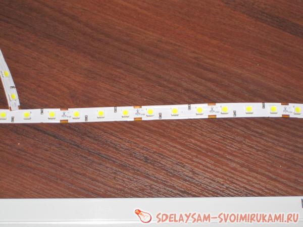
Then I bought led strip... I didn’t just buy it, but it took a long time to choose more, to be precise. There is a wide variety of LED strips in the electronics market: both colored and white, and small and large. Stop your choice on a tape with natural light (not cold and not warm - pure white), with a power of 14 watts per meter when powered by 12 volts.
Here is its diagram:

As you can see from the diagram, the LEDs are connected by 3 in a group. I will rework this circuit to connect a 230-volt AC LED strip without any expensive and unnecessary converters.
We disassemble the lamp.


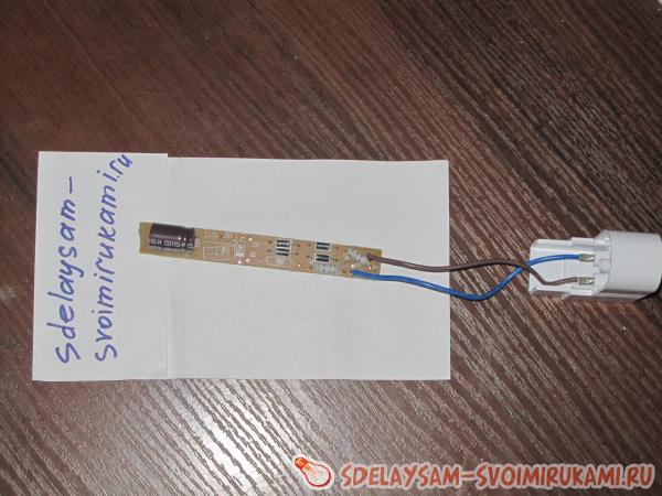
We see inside pulse converter for fluorescent lamp... We put it off not far - it will still be useful to us.
Now we need to do some small calculations to calculate how many LED groups we need for a 230 volt network. 230 volts after rectification will turn into 250 V, or even more, there is such an effect of converting alternating voltage to direct voltage. We take 250 volts and divide by 12 V (so one section of three LEDs is powered by 12 volts), we get 20.8333. We always round up and take another section in stock, and we get 22, that is, 22 sections. In total, there will be 66 LEDs shining. Serial connection diagram:

I connected it like this: I cut out pieces with scissors and soldered them with a wire, see the pictures.

![]()

Next we need a rectifier direct current, I made it from the same lamp. We take out the converter torn out of the lamp and bite off the capacitor. The diodes with the capacitor are located separately, so you just need to break off the board in the appropriate place, you practically don't have to solder, except for just the wire.
Here is a diagram, in case anyone is unaware of what this is about.


a series-connected LED strip (of 22 sections) I got about a meter long. Naturally, it is difficult to conclude this number of LEDs in one lamp - it is very narrow, and it is not necessary. Therefore, I bought two lamps, connected them in series, glued an LED strip in one row to each. Self-adhesive tape with adhesive layer, but I advise you to additionally smear with superglue. Glued, assembled, connected.


I can't say anything about the minuses, but about the pluses: It shines one and a half times better than the previously installed 13-watt lamp. Two fluorescent lamps consumed 26 watts, while here two consume less than 10 watts. Durability, reliability.
The biggest plus, in my opinion, is the directionality of the glow: they practically do not shine to the side and do not dazzle, but the table is illuminated perfectly.

Keep up with the times friends! All the best!
This short article will discuss how to do it yourself fluorescent lamp based on electronic ballasts for utility and technical rooms, which do not require external beauty and exquisite design from the lamp. The luminaire will be designed for tubular fluorescent lamps with G13 base, 1200 mm long. These lamps have low price and are capable of lighting great at th area.
To make a lamp you need:
- Frame. It can be made from scrap material. In fact, the body is just a rectangular piece made of non-combustible material (metal, textolite, electrical plastic, etc.). You can use an old body from a worn-out "ancient" lamp.
- Electronic ballast - electronic ballast. It is also called "electronic choke". Compared to a conventional choke, electronic ballasts have a number of advantages at the same price: instant start of lamps, no lamp flickering, low dependence of lamp brightness on supply voltage drops. This article describes a luminaire based on 2x36 W electronic ballasts.
- G13 sockets at the rate of two sockets per lamp.
- Monofilament copper wires section 0.2-0.5 sq. mm. You can also use multi-wire (flexible), tinned the ends.
- Suitable screws, nuts for attaching all parts to the body.
The manufacturing process of the luminaire is reduced to the following mounting and connection operations.
- Fixing the sockets at the required distance from each other, depending on the length of the lamp and the desired distance between the lamps.
- Electronic ballast mountings. Since the electronic ballast heats up during operation, it is recommended to place it so that the electronic ballast receives a minimum of additional heating from the operating lamp. The minimum heating zone of the lamp is closer to its center.
- Connecting cartridges to electronic ballasts using pre-prepared wires the desired length and according to the wiring diagram, which is usually drawn on the electronic ballast housing. The wires are simply inserted into the holders and held inside by a leaf spring. For this reason, it is betteruse monofilamentwires, since it is almost impossible to stick stranded wires (without preliminary maintenance).
- Fixing the luminaire to the ceiling or wall. Connecting the luminaire to a 220 V power supply.
Despite the fact that the presence protective glass for lamps low pressure optional, it is advisable to cover the lamps with a suitable transparent material, in order to avoid accidental damage glass flask lamps. Photos of the manufactured luminaire and a drawing with a wiring diagram are attached.

For reliability, the luminaire body (left, right and between the sockets) has been reinforced with metal corners.


ECG on the lamp. The electronic ballast is located between the lamps, closer to their center (in the zone of minimum heating).
Connecting the socket G13.
A typical socket G13 for a fluorescent lamp is connected without the use of tools, it is enough to remove the insulation from the wire for a length of about 1 cm and insert it all the way into the hole. The wire must be solid and of an acceptable cross-section (according to the specification for the cartridge). In the case of using a stranded wire, it must be tinned or crimped into a sleeve lug. Inside the cartridge, the wire is held by a flat-spring contact made of elastic non-ferrous metal. The G13 socket, as a rule, has four holes for entering wires - two for each contact. Thus, it is possible not only to lead the wire into the cartridge, but also to branch the wire from the cartridge, which is often required. If you need to remove the wire, you need to press a special lever inside the case with a thin awl, while the contact bends, releasing the wire.

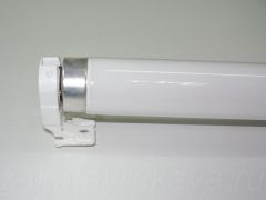
To install the lamp in the holder, it is necessary to place the contacts in the slot at the same time from both ends of the lamp and turn the bulb through an angle of 90 °.
Chuck G13 closed. The central black pivot piece blocked the exit of the lamp contacts through the slot in the holder body.
![]()
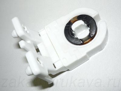
Holes for wires. The same color of the arrows indicates the connection to the same pin.


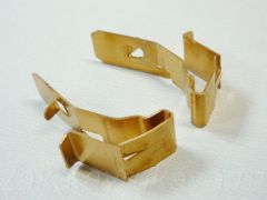
Flat spring contacts.

A flat spring presses on the wire, at the same time keeping it from being pulled out.
![]()

Holes (yellow arrows) required when removing the wire (photo above).
A platform on a flat contact (shown in disassembled form for clarity), which must be pressed to release the wire (photo below).
Time has shown that this self-made fluorescent lamp starts up well and works in the ambient temperature range from -10 ° ... + 30 ° C, more extreme temperature tests have not been carried out. The luminaire is insensitive to high room dust and power surges (which may occur, for example, during use welding machine or starting powerful electrical equipment), great for organizing quality lighting in a workshop or garage. To make the light more pleasing to the eye, it makes sense to install lamps of different color temperatures(as in the pictures above).