A properly installed fire alarm is the key to the safety of your property and own safety. There are several available on the modern market effective systems, working on different principles. Explore the features available options, select the most suitable type of fire alarm, and then read the guide for calculating and installing sensors and what to do in case of a false alarm.
There are systems that use smoke and heat sensors. The principle of operation of the devices is clear from their name: thermal sensors are triggered when the temperature rises, while smoke sensors are activated when smoke forms within their range. The sensors can be directly powered by special control and control devices or batteries.
Good for home addressable analogue system, and address-interrogation signaling. Installations of the addressable survey type find fires as quickly as possible. Modern addressable analogue alarms are able to determine the location of the fire and even take some actions, for example, turn off ventilation system, close or open everything in the house, turn on sound alarm and so on.
Modern ones are available for sale fire alarms with built-in GSM transmitter. In the event of a fire, such a system will call or send an alarm message to a specified number. This will give the owner the opportunity to immediately call the fire department and personally come home. Modern GSM systems can be programmed to notify several phone numbers at once, which is very convenient.
The nuances of installing and maintaining a fire alarm system
Fire detectors must be installed on every floor and in every room of the house. Attics and basements are also no exception. The best place The ceiling is used to place fire alarm sensors.

You can install the sensors yourself, but if possible, it is better to entrust this work to a licensed company.
Once installed, the alarm system will require regular maintenance. If the sensors are powered by batteries, check the functionality of the controllers every month. The batteries themselves usually use up their life in a year. It is recommended to replace the sensors with new ones at least every 7-10 years.
If the system elements are powered from lithium battery, sensors also need to be tested monthly. If it is necessary to replace the battery with a new one, all warning devices must be replaced at the same time.
If your apartment or house has a wired system, check its serviceability every month. The power supply needs to be changed annually. The service life of the entire system is on average 7-10 years.

During installation fire protection system pay special attention to the cross-section and location of the cables. Consider the fact that in the future you may want to redesign rooms or make basic repairs. Try to think things through so that any repairs can be performed without making changes to the alarm system configuration.
Provide reliable protection systems from various kinds unacceptable external damage (insect damage, chemicals etc.). The norms and rules for installing the systems in question are dictated by the relevant GOSTs. Carefully study the current regulatory documentation before starting installation work.
Buy equipment only from verified and licensed suppliers. Alarms of dubious manufacture usually behave unpredictably. For example, they often operate without any hint of a fire, but during a real fire they remain stubbornly silent. Therefore, do not skimp on your own safety and buy a high-quality system from a reputable manufacturer. All the same, the alarm system will not have to be replaced very often.
After installation, set your alarm to service maintenance. To do this, it is better to contact a specialized company.
In preparation for installing a fire alarm, a number of special calculations must be performed. They will help you choose the most best option systems and avoid unnecessary costs during installation and maintenance of sensors.
One of the most important stages of alarm calculation is Determining suitable power supply capacity. Decide which energy source will be most convenient for you to connect the sensors to. There are quite a lot of such sources: from ordinary batteries to solar batteries.

The required battery capacity is indicated in the instructions for the alarm. Check the value found with the information on the battery case. If the battery capacity is not enough, purchase a more powerful battery or connect several batteries in parallel.
If you connect multiple batteries in parallel, make sure their voltage is the same. Otherwise total capacity battery circuit will decrease.
Check the required wire cross-section for connecting fire alarm sensors. This information is usually provided in the system manual. Also pay attention to indicators such as battery capacity for standby and alarm modes. Add these values up and you will get the total required battery capacity specifically for your system.
Connecting an alarm using the example of typical sensors
First stage . Define required quantity alarm sensors. To determine the required number of controllers, you need to know the area of the room served and the ceiling height. In the current regulatory documentation it is said that if the ceiling has a height of no more than 350 cm, then one sensor is sufficient to service 80 m2. At the same time, fire safety rules require that even in the most small room there were at least two controllers. Follow the last rule.
Second phase. Mark locations for installing fire detectors. Maximum permissible distance from the wall to the sensor, according to regulatory documents, is 450 cm. The sensors themselves must be installed in increments of at least 900 cm. This rule is relevant for situations where the ceiling is single-level and its height does not exceed 350 cm.
Wall-mounted models of fire sensors should be placed at a distance of 200 mm from the ceiling surface.
Third stage. Fix the sensors at the marked places and connect them to the power source using two-wire wires. The sensors are connected to each other in series. You need to install a resistor in the terminal block of the last controller.
Fourth stage. Test each sensor after connection. To do this, light a candle and pass its flame near the detector.
If the fire alarm goes off without any sign of a fire, you need to follow a few simple steps to turn it off. Otherwise, loud sound alerts and the activation of unnecessary additional funds will cause you a lot of trouble.

First option. Find out why the alarm went off in the first place. You cannot turn off the system without first checking all serviced premises. Quality systems extremely rarely they work without any reason. Maybe there was smoke or a real fire in some room of the house. If there is an “irritant”, eliminate it, and the system will turn off on its own. Be sure to check the condition of the electrical wiring.
Second option. If you have not found any reasons for the alarm to go off, proceed to turn it off. The shutdown procedure depends on the type specific system. The simplest option is to disconnect the alarm from the power source. However, this option can be considered solely as a temporary solution to the problem, because With a disabled alarm, you are jeopardizing the safety of your home and everyone in it.
Third option. If your home has a centralized control panel, turn off the alarm from it. In some situations, this procedure requires entering a special code. If you don't know it, contact the company that services your fire alarm.
Fourth option. If the controller becomes very dusty, for example, when repair work, to turn it off, it will be enough to remove the front panel from the sensor and rub its “insides” with a cotton swab lightly moistened with alcohol. If this was the problem, after such cleaning the alarm will turn off. From now on, monitor the condition of the sensors and clean them promptly.
Fifth option. If you need to turn off the fire alarm in a particular room, you can wrap the sensor with adhesive tape. However, after such processing the controller will become useless. Remove the tape immediately after identifying and correcting the problem.
Sixth option. If none of the above helped, use the most radical solution - cut the wires connected to the sensor. The fire alarm will turn off, but will become completely useless until you repair it. Try to figure out the cause of the false alarms of the sensors as quickly as possible and eliminate the malfunctions.
If this is possible, contact a specialized company. Its employees will diagnose the fire alarm system and give recommendations on further actions from your side.
Thus, in self-installation There is absolutely nothing complicated about fire alarms. You just need to understand in detail the sequence of connecting the sensors and follow the instructions. Be sure to check the manufacturer's recommendations. Many modern systems have a number of features that need to be clarified separately. Your safety depends on the correct installation and connection of sensors, remember this.
Good luck!
Video - DIY fire alarm installation
The fire alarm system is a necessary condition for the construction of some objects. First of all, this applies to buildings where explosive substances are stored. This includes buildings in the healthcare, general education, and manufacturing industries.
The safety of any premises depends on the correct installation of fire alarms. Incorrectly performed installation work will not only not protect the structure during a fire, but will also contribute to the issuance of fines.
Alarm device
The main function of a fire alarm system is to detect a fire in a room using installed systems sensors Modern manufacturers I propose to use the following sensors in fire alarm systems:
- optical;
- smoke;
- thermal.
Optical sensors are capable of detecting infrared or ultraviolet radiation that is released during the combustion process. Smoke detectors respond to increased smoke levels, and thermal detectors respond to a sharp increase in temperature. Often, for system reliability, devices are combined different types.
All sensors can be divided into wired and wireless. All of them are connected to a central console, which receives the corresponding signals from the sensors. After processing the information, the location of the fire is determined, a control signal is turned on, which starts the warning and fire extinguishing system.
This system is quite complex, so installation of a fire alarm can be carried out if there is project documentation, which takes into account the purpose of the object.
Design, connection and maintenance of alarm systems are permitted only to those companies that have certificates and licenses to carry out this work.
When preparing design documentation, they develop technical task. It is subsequently used to make a layout of cables and devices.
Installation norms and rules
The list of all norms and rules that describe installation features is quite large. But the main ones should be mentioned.
Acquainted with full list rules you can in GOST and SNIP. In addition, you should pay attention to the Federal laws on which the design documentation is based. It is also necessary to comply with the requirements of Fire Safety Standards.
If the installation requirements are not met, it is necessary to dismantle the installed equipment and carry out all work in accordance with the standards. In this case, dismantling will be carried out at the expense of the performing company.
The installation of a fire alarm must be carried out taking into account all the requirements:
- fully comply with the design documentation and the specifics of the premises;
- high-quality performance of work.
In a protected building, it is advisable to divide all the premises into several control zones, in each of which a certain number of sensors are installed.
Electrical network standards
Power and communications networks also focus on Special attention. After all, they must be resistant to fire. As the room temperature rises, their insulation must be maintained.
Communication and power wiring must be laid in different channels. Where they intersect with the electric main, they must be equipped with additional reliable insulation.

The central control panel must be located in a specific room. Access to it should be limited service personnel. There are several types of control panels. Each of them can be used in certain conditions. Accordingly, the assembly of each device is individual.
When choosing, choose a conductor with a larger cross-section than for lighting fixtures.
Installation
Current legislation does not prohibit installing fire alarm systems yourself. All work must be carried out in accordance with certain rules that are prescribed in the project documentation.
But experts recommend that the system be installed by professionals. On your own, with the skills to work with such systems, you can assemble a system for your home. Complex designs should only be carried out by specialists who guarantee the serviceability of the structure as a whole.

Specialists connect the sensors in accordance with previously prepared diagrams and instructions for the devices.
An example of installing a foam or water fire extinguishing device. They are used in libraries, shops, hospitals, hotels, etc. The water flow in such a system must be at least 10 l/s. In case of fire, the water supply should be at least 30 minutes, and the distance between sprinklers should be no more than 4 m.
The installation of a fire alarm should be carried out at a temperature of about +200, humidity of about 60%, in the presence of supply and exhaust ventilation.
After installation of the structure, it is necessary to carry out inspection work.
The cost of installing an alarm directly depends on the area of the protected premises, and, accordingly, the amount of equipment used.
End of work
After the installation of the fire alarm system by the performing company and the customer, it is necessary to draw up a summary executive documentation. It is necessary to prepare the following documents:

- journal and executive diagrams;
- certificates of statements and tests, examination of hidden work;
- quality certificates of the materials used, their certificates;
- working drawings.
A complete list of all necessary documents can be found on the website of the Ministry of Emergency Situations.
How to disable the fire alarm system
Well, the connection is made in accordance with all the rules. The work order was followed. But during operation fire system may be triggered for no reason. At this time, you need to make sure that there is no fire, after which the device must be turned off. We figured out how to connect the systems, but how to turn them off? After all, an unpleasant specific sound is often produced. To turn off the alarm you must:
- determine the reason why the alarm went off. Maybe for some reason there was an accumulation of smoke in the house or a small fire broke out. In this case, the room must be well ventilated;
- If no reason is observed, then you need to turn off the device. A simple alarm can be easily turned off by turning off the power source from the sensors. The difficult one involves turning off the system from rooms with a central control panel. In this case, you will need to enter a certain code;
- radical method of elimination unpleasant sound is the cutting of wires. But remember, to restore the functionality of this alarm, in this case it will be necessary to carry out a number of sequential works.
Installation of fire detectors certainly implies their connection into a fire alarm loop. The connection diagram for fire detectors is given below. Two-wire (most commonly used) are considered
- fire smoke detectors (DIP),
- thermal fire detectors (IP),
- manual fire detectors (IPR).
The connection diagram for security detectors is shown on another page.
A fire alarm loop can simultaneously contain detectors of one or more (combined alarm loop) of the specified types. In addition, the connection diagram for fire detectors may provide for receiving control device fire alarm (generation of a “fire” notification) when only one fire alarm loop sensor is triggered or when two or more fire detectors are triggered. (such organization of the fire alarm loop after the activation of one detector generates an “attention” signal).
Addressable fire detectors also have their own connection diagram. I would like to note that the connection diagram for fire alarm sensors may vary (depending on the type of control panel), however, the differences are insignificant, mainly affecting the ratings (values) of additional (ballast), terminal (remote) resistors.
In addition, different types of control and monitoring devices allow the connection of different maximum quantity smoke fire detectors into one alarm loop - this value is determined by the total current consumption of the sensors. Remember, the current consumption of a smoke detector depends on its type.
All types of non-addressable two-wire smoke detectors use the same pin numbering: (1,2,3,4).
Pin connection diagrams smoke detectors from different manufacturers they may visually differ slightly (options 1,2), but, from an electrical point of view, they are identical, because inside the detector body, pins 3,4 are short-circuited.
However, the second option has a serious drawback - when the detector is removed from the socket, the control device will not detect its absence and will not generate a “fault” signal. Therefore, it is better not to use it.
Note!
- Even for one specific type of fire alarm control and control device, resistors Radd. may have different values (determined by the current consumption of various types of smoke detectors, read the device data sheet carefully).
- Connection diagram shown fire manual call point is valid when its executive element is normally closed electrical contacts. For example, for IPR 3 SU this connection diagram is not suitable.
- Thermal fire detectors are connected according to the above diagram if they have normally closed contacts (the majority of them).
- A situation may arise when an IPR, connected according to the above diagram (recommended in the device data sheet) for an alarm loop that provides for activation by two sensors, when triggered, causes the receiving and control device to generate an “attention” signal instead of a “fire”. Then try to reduce the value of the resistor (Radd), through which this IPR is connected to the alarm loop.
- Before connecting (installing) addressable detectors, their address must be pre-programmed.
- Connecting smoke fire detectors requires compliance alarm loop polarity.

Fire and security systems are in demand and are used at a wide variety of facilities. The complexes differ in functionality and are presented in a wide variety. Therefore, before installing an alarm, it is best to know the features of different types of equipment.
Alarm system and its operating principle
The security and fire complex consists of equipment that allows timely detection and notification of danger. Key element are sensitive sensors. They react to rising temperatures and smoke, notifying owners of a fire. The system is activated automatic fire extinguishing, sound signal about danger. This way the equipment allows you to save life and property.

Sensors are placed on the ceiling
The complex of devices includes sensor devices, which are presented in the form of sensors and detectors. Processing of information received from sensors is carried out by other devices, and the control unit allows you to control the operation of the system. The set of devices also includes peripheral components that are connected to the control panel:
- control panel;
- printer for printing messages;
- sound and light alarms;
- module for short circuit isolation.
All devices interact with each other, providing timely notification of home owners about danger. The configuration of the system may differ in functionality and the type of elements used, but the security and fire system works as efficiently as possible when configured correctly.
Design and calculation
For arranging a security and fire complex system in a room, it is important correct project, allowing you to create a complex that meets the established requirements. A single standard presupposes that the system complies with basic standards, which is necessary for correct and efficient work alarms. Design is important stages. The premises are inspected, and in this process the specialist receives the information necessary to calculate the parameters. And also design involves taking into account the following GOST requirements:
- conductive external or internal pipes designed using the ring method. Conductive installations can be dead-end, but only for control nodes of less than three. The length of the external dead-end wire should not exceed 200 m;
- sanitary or industrial complex equipment cannot be connected to the pipelines supplying power to the fire extinguishing system;
- pipelines are attached to the main structural elements of the house, but do not support other structures;
- the estimated volume of water for the fire extinguishing system must be stored in water supply containers, but it is important to provide for the presence of devices that prevent the flow of liquid for other needs;
- The period of filling the design volume during local extinguishing cannot exceed 180 s.
When calculating, it is worth considering that one sensor monitors a square in space with sides equal to the height of the ceiling, but not more than 4 m. The design and calculation of systems are carried out taking into account the requirements of GOST R 50800, as well as GOST 3262. NPB 88–2001 is often the main document , according to which a complex of pipelines is being installed.
Fire alarm: types of systems
There are main types security and fire alarm system, differing in parameters, functionality and installation rules. Complexes different levels complexities are necessary for fire warning and differ in their operating principle.
Non-addressable fire alarm
A non-addressable system involves the use of receiving and control devices that measure the current in the alarm loop with installed detectors. These elements can be in the following states: “fire” or “normal”. If a fire is detected, the internal resistance in the detector changes abruptly, as well as the current in the system loop. As a result, an emergency alert is generated.

The traditional signaling circuit is simple
Addressable analog complex
In this equipment complex, the control panel (RCD) is a monoblock with one or several loops. They have a ring structure. At the same time, it is easy to connect up to 200 elements to one loop. The ring complex includes the following components:
- addressable automatic fire detectors;
- addressable manual fire call points;
- address relays;
- addressable sirens;
- control modules.
In an analogue addressable system, the detector is not responsible for deciding whether there is a fire, but is only a measuring device. The sensor transmits information to the control panel about the received parameters, which makes it possible to distinguish a malfunction electrical circuit detector against dust accumulation in the smoke chamber. Equipment of this type does not use single indicators to make a decision about a fire, but pre-prepared information about the state of the controlled space. In this case, intermittent short-term interference is not perceived, but persistent indicators and signals from a real ignition source are taken into account.

The system is efficient and easy to use
Threshold type system with radial stubs
In a threshold-type complex with radial loops, there are special fire alarms that are already configured to a certain threshold or level for operation. The thermal sensitive sensor is responsible for deciding whether a fire occurs when a certain temperature threshold occurs, and then an alert is given. The peculiarity of the complex is the radial topology of the cables. So, loops of wires with connected detectors are diverted from the central unit. Up to 30 warning elements can be connected to one beam. When one of them is triggered, the loop number is displayed on the main panel, but it is impossible to obtain other information.

The threshold system design is quite simple
Threshold alarm with modular structure
Systems of this type do not have a central receiving and control device. It has been replaced by interconnected blocks that are placed next to sensitive sensors. Such blocks receive signals from 100 or more loops. When installing an alarm system with a model structure over a large area, it is necessary to increase the capacity of the receivers by installing additional blocks. Receiving devices transmit signals to the main panel. This system also installs one- or two-threshold wire loops. Using the latter option, it is easy to detect a fire and find out about its level.
Modern types of sensors
Sensors various types present in any type of security and fire alarm system. Their number and functionality may vary, but it is thanks to sensitive devices that the system reacts to a fire. The classification of devices depends on the type of signal transmitted, the type of parameter change being monitored, and also depending on the location and type of sensor. Sensitive devices are classified by purpose, and one system may include several types of elements. This ensures the functionality of the fire and security alarm system.
temperature sensor
Heating devices that are sensitive to an increase in room temperature are always present in fire and security alarm systems. The action of such a device is activated when the air temperature in the controlled environment increases. Some devices operate based on changes in electrical resistance based on changes in temperature, while others use deformable structures.

The sensors also differ in appearance
Smoke detectors
Sensitive components that are triggered when smoke appears are in demand and effective option for security and fire alarm systems. They quickly detect smoke manifestations and allow you to take the necessary actions in a timely manner. For example, short circuit electrical wiring often occurs with poor access to oxygen and is characterized by a long period of smoldering. In this case, the smoke detector gives necessary signal and the fire extinguishing system is activated, if such a design is provided for in the project.

The smoke detector is unnoticeable on the ceiling
Flame sensor: operating principle and features
High-quality flame sensors actively respond to an open fire or smoldering hearth. The devices are practically not used in residential areas, but they are effective in industrial or open areas. The principle of operation is based on the fact that the flame is always accompanied by electromagnetic radiation, the degree of which depends on the intensity and temperature of the fire. Radiation is divided into visible, infrared and ultraviolet. The sensitive component of the device quickly detects such manifestations in one or more ranges. Such sensors are often used in the gas and petrochemical industries.

The appearance of the flame sensor is quite simple
Gas sensor
This device is very rarely used in automatic fire extinguishing alarms, since there is a high risk of false alarms. For domestic purposes, the sensor is effective and notifies of gas leaks from communications. The device reacts to manifestations of carbon monoxide or carbon monoxide.
Installation and connection of security and fire alarm systems
Installation security and fire system requires proper design, which is carried out taking into account the area of the premises, the type of sensors and other factors. At the initial stage of work, it is necessary to calculate all the parameters of the system, which only a specialist can do. This is due to the complexity of the alarm system, which includes many devices.

The system may include several types of sensors
A simple warning system can be installed in a private residential building or apartment. In this case, you need to select devices with optimal characteristics, as well as determine the location of their installation.
Recommendations in video format allow you to master the installation technology step by step. You can learn the specifics of installing and connecting devices in a private home from the video instructions.
Video: fire alarm installation
Installation of fire detectors
Before installing the system, you should determine the installation location of the sensors. Sensitive devices are optimal in areas of high fire risk: in the kitchen, in the living room with a fireplace. In the house, the devices are installed in the boiler room if there is a gas heating boiler. In this case, it is best to use combined sensors that will respond to open flames, smoke, and gas.

For installation, you need to determine the number of sensors
For proper functioning, you need to take into account the rules for choosing the location and installation of sensitive elements:
- the distance between sensors should be 9 m, and from corners and walls - 4.5 m;
- the correct diagram is the key to the correct arrangement of elements;
- sensors are installed at a distance from heat and flame sources;
- in narrow and long corridors, you must first take into account the gap between the sensors.
Action of the warning system
For household use Local warning systems are often used. The complexes may not have a common centralized control, and the sound signal is recorded in advance. The system requires an amplifier and a speech processor. The disadvantage is that it is impossible to quickly manage evacuation using the equipment. Control is important when non-standard situation or in the case of rapidly changing events.
Possible malfunctions after installation
All fire and security alarm malfunctions are often associated with incorrect installation of sensors. If the distance between elements is violated or if they are located close to heating devices, a continuous beep may sound. The following factors can lead to malfunction:
- low quality sensors;
- electromagnetic interference;
- strong acoustic vibrations;
- dust and insects getting into the sensors;
- malfunction of the device design.
If any violations are detected, it is best to remove the alarm, determine the cause and fix the problem. In any case, you should not use low-quality devices that will not ensure safety.
How to remove an alarm with your own hands?
Dismantling a security and fire alarm system includes the removal of all the elements that make up the complex. If sound notification is false, you should make sure of it. If there is no source of ignition, smoke or gas leak, the sensors must be turned off. To do this, remove the battery from them or turn it off from the centralized control panel. To temporarily deactivate sensors in only one room, cover the sensitive element with adhesive tape or film.
Security and fire alarm sensors are important components systems. The correct operation of the entire complex of devices depends on the quality of their connection. You can master installation and connection using video recommendations.
Video: connecting sensors
Security and fire alarms are effective and provide security. Correct installation and selection of sensors - important points for correct operation of the system. To do this, design is carried out, as well as the features are mastered and the characteristics of the devices are selected.

It has always been difficult to honestly ensure your well-being, but losing what you have justly acquired in a fire or theft is a shame, and you need to earn money again... A fire and security alarm (FS) allows you to reduce the risk of property loss due to misfortune to a minimum, and the insurance premium rates for housing equipped with it are significantly below. Nowadays, another favorable circumstance has appeared - the installation of a fire alarm can be done by a person familiar with the basics of electrical engineering and household work, and the legalization of a correctly assembled system most often does not require compliance with complex formalities.
Really? OPS is a serious matter; the Ministry of Emergency Situations must respond to an alarm. And by law, the installation of a fire alarm must be carried out by a licensed organization, everyone knows this. Yes, but modern electronics have so simplified the construction of automatic security systems (AOS), while at the same time increasing their functionality and reliability, that, figuratively speaking, well-fed wolves vigilantly guard the grazing herd: professionals have a stable income, focusing exclusively on security functions, and citizens without straining your budget, ensure your safety.
To understand why do-it-yourself security and fire alarm systems have become quite real, and how to do it correctly, let’s briefly take a look at the evolution of AOS, the design of their entirety and its component parts, and the principles of organizing security services for residential premises.
How AOS developed
Before chips and reed switches
Initially, AOCs were built in the form of a chain of opening temperature sensors: spring contacts were soldered with Wood or Rose alloys with a melting point of 70-86 degrees. The chain was forcibly closed manual call point with normally closed contacts. All this together formed a loop Ш. When heated, the solder melted, the contacts diverged, the circuit broke, the relay included in it, also with normally closed contacts, was released, its contacts closed and turned on an alarm. By pressing the detector button, it was possible to give an alarm manually.
Such systems at the very least worked as local ones, but for communication with the central control panel they required a long line (LAN), prone to faults and having its own leakage resistance, wire resistance, capacitance and inductance, which could cause both false operation and non-operation due to real danger .

Therefore, on the consoles they began to include rays - loops from the LS - into the diagonal of the electric bridge, and into its opposite diagonal - the balanced circuit of the BC (see figure). The beam was no longer characterized by the resistance of the loop R Ш, but by the total resistance (impedance) of the subscriber Z A. By adjusting the BC, we achieved equality of its impedance Z to the impedance of the subscriber Z A. Under this condition, the potentials in the diagonal of bridge 1-2 turned out to be equal, and the voltage U 1 -2 =0. When the sensor was triggered, U 1-2 >0 occurred, which triggered the alarm.
The AOC bridge circuit made it possible to make an important improvement: They began to turn on a resistor of a strictly defined value R Ш in parallel to the detector. This made it possible to judge the nature of the operation by the value of U 1-2: if R Ш remained in the circuit, then someone pressed the detector button, then U 1-2 will be approximately half the maximum ; This is an "Attention" signal. If the sensor opens, we will see a clear open circuit and a maximum of U 1-2; this is “Anxiety”.
Such a system was not very reliable: the slightest malfunction would give a false alarm, a team would come out, and then the installer, expressing his thoughts on this matter in any form, would go to find and fix it. False alarms reduced the degree of trust in the AOS and from the order to the installer the facility remained open. Moreover, splashes of solder sometimes got between the open contacts, and the sensor, “squeaking,” calmed down again. There were cases when criminals shot at the sensors with an air gun through the window, and when they saw that the squad had left, they knew that they had at least an hour to “do the job.”
The BC also caused a lot of trouble: the drug parameters fluctuated greatly. A worker with an electrical engineering education working on a control panel was greeted by the police and firefighters with open arms, but often soon had to sign a statement “on his own”: the salary was small (it wouldn’t go under knife or bullets), and the hassle was no less than that of opera operators.
In large facilities consisting of many subscribers (department store, post office), beams from the premises were combined into a local console - control panel(PKP), which automatically gave an alarm over the telephone line when one of the beams was triggered. This made it possible to reduce the dependence of the BC on the state of the drugs, which were already under the control of the signalmen, but reduced reliability: having competently delved into the control panel, it was possible to disconnect the entire object from the remote control and operate there for your own pleasure.
At the same time, attempts were made to use parallel connection sensors with thermobimetallic normally open contacts, shunted R Ш. In theory, this would allow the value of U 1-2 to judge from a remote control the location of the trigger, which a sequential system does not allow. However, the open bimetal turned out to be extremely unreliable: the sensor with oxidized contacts did not announce itself in any way in advance, and then remained silent, like a fish on ice, when the fire was already blazing with all its might.
Reed switches
Sealed magnetically controlled contacts - reed switches - made the first revolution in AOS and OPS. Reed switches can withstand billions of operations without oxidizing the contact surfaces, and the problem of temperature operation was easily solved by using holding magnets made of materials with a Curie point of 70 degrees: when heated, the magnet stopped magnetizing and the contacts opened.
The principle of the reed switch allows it to be switched, which gives a reliable sensor suitable for both serial and parallel fire alarm systems. True, the accuracy of determining the location of the trigger analog ways remained low, so parallel analog OPS did not become widespread. Nevertheless, it was thanks to reed switches that a fire alarm in the apartment appeared: the reliability and low cost of the sensors ensured the cost of the system, affordable even for the average Soviet consumer.
The first smoke detectors also belong to the “reed switch era,” but they were by no means household ones: smoke detection was ensured by ionization of the gap between the fixed contacts, for which it was illuminated by an ampoule with a radioactive isotope. Alarm installers were afraid of such sensors, in a thick steel case and marked with a radiation hazard sign, as if they were fire, and they were rarely used at particularly important facilities.
At the same time, PKPs also began to transform: the use of microcircuits with a medium degree of integration and analog-to-digital converters (ADCs) made it possible to simplify the BC or completely abandon them and measure the beam parameters directly. The first wireless control panels with autonomous power supply also appeared, which, regardless of telephone lines, gave an alarm to the remote control using the Altai system - the prototype of modern mobile communications, invented in the USSR back in the 50s.
Chips and lasers
A real revolution in the OPS was carried out and made publicly available by the big integrated circuits(LSI, chips) and miniature semiconductor lasers. This affected all links of the OPS, and in new system The best of previous achievements fit in organically (see the picture earlier in the text below).

Sensors using laser detectors monitor temperature and smoke in several parameters at once, which eliminates false alarms (see figure on the left). Some sensors combine the functions of motion detectors; they will be discussed below. “Smart” sensors can also be autonomous, equipped with a built-in battery.
The control panel of our days is a computerized device that can work both with “smart” junior colleagues and with old, but absolutely fail-safe and very cheap reed switches. This made it possible to include SPU in the household fire alarm systems - a signal and triggering device, which, based on a signal from the control panel or directly from the sensor, includes indicator boards, flashing lights, sirens and opens valves automatic system fire extinguishing
Modern alarm systems are digital-analog parallel-addressed: each sensor has its electronic address stitched into it, and the control panel knows exactly where everything happened. Using advanced software, analog sensors are also quite accurately controlled by loop parameters. The alarm signal is sent via GSM to the owner’s mobile phone and to the security company’s computer. The alarm can be duplicated directly from the chip sensor, and the activation of the control system can also be triggered from the gearbox.
Motion sensors on the same chips and infrared lasers have made the alarm systems truly security: they control the entire volume of the room or the area of the yard. The laser scanner signal is converted into a code, and the control panel processor continuously compares the codes one after another, filtering out interference from weather, precipitation, and small safe objects.
The capabilities of a modern fully functional security system are presented in the figure. This one is quite expensive, but the system is simpler, quite reliable for an apartment, and you can assemble it yourself. How will be described below, but for now let’s see what is needed and what can be achieved in general:

- Source uninterruptible power supply(UPS) is necessary for the alarm system to continue to operate in a de-energized apartment;
- Universal sensor-announcers: on the left is a group of autonomous ones, for example. in the garage;
- Motion sensors;
- Electronic lock;
- Reed anti-burglary contactor;
- Sign board;
- Local alarm;
- Display with control panel;
- Automatic OPS.
Let's give some explanations. Firstly, reed tamper sensors are still in their place, not competing with motion sensors, and the point is not only in cheapness and reliability. The small reed contactor is easy to hide; its operation is not detected by the anti-scanner. The search for such a “bug” (and it is unknown whether it exists at all) with skillful installation requires so much time that hacking loses its meaning.
Secondly, instead of any of the devices in pos. 7, 8 can be connected to SPU. Thirdly, according to item 10: the power supply of the alarm system must be supplied from a separate circuit breaker turned on BEFORE the apartment one, otherwise reliable operation system is not guaranteed. And finally, a remote control with an access code display allows you to independently reset, test and reconfigure the alarm system.
Organizational structure
A radical improvement in the technical base has also entailed an improvement in the organizational structure of the emergency response system: subscribers rarely connect to the EMERCOM console, it is expensive and overloads both equipment and personnel. The role of signal concentrator was taken over by private security firms. It does not light up or is stolen everywhere and not always, and with an acceptable load they can gain a lot of subscribers, which provides a decent income for a small monthly fee.
This system is also beneficial for the owners: a private licensed security guard will be happy to advise, help with advice, and he has no experience in interacting with the Ministry of Emergency Situations and the police. And since the owner still pays him with his hard-earned money, it is easier to demand it if something happens than from a government agency.
Let's take care of the alarm
Do you need a project?
A fire alarm project is needed, and not so much for formal reasons. Only a security guard with extensive experience will be able to accurately indicate the location of devices, their types and connection diagram. Otherwise, the flame can rage beyond repair, and the attacker, immediately spotting the “homemade” (they are well versed in alarms), will only grunt and, having “bombed the hut”, will sit at ease in the owner’s favorite chair, drinking the owner’s cognac, smoking the owner’s cigar, gently stroking the bag on her knees, tightly stuffed with the owner's goods and looking ironically at the sensors in full combat readiness.
However, security companies, generally rightly believing that the main thing is real security, not paperwork, often make concessions to potential subscribers: they agree to do a cheaper project, a sketch, or limit themselves to an even cheaper consultation: where to install which sensors, where to place the alarm control panel, what cable and how to connect everything.
Then, after checking the work, they put him under guard, and based on the documents, they pass him by retroactively. The owner is no worse off for this: once the contract is signed and the apartment is already under control, the security guards bear all the responsibility. The components of a modern fire alarm system are completely reliable; fire alarm maintenance comes down to periodic checks of its operability and readiness, which, together with the security company on duty, can be carried out by the owner himself, so, as a rule, there are no problems with service.
How to do what?
The law does not prohibit you from making an OPS yourself, but they won’t take one on the remote control. We will have to limit ourselves to displaying an alarm on a mobile phone, but this is already a serious help in misfortune: the Ministry of Emergency Situations and the police are obliged to respond to any signals from citizens. Therefore, we will describe which equipment to choose for which case, and how to correctly assemble it into a workable whole.
PKP
The types of modern control panels are shown in the figure. The first one on the left is a professional multi-beam analog-to-digital one. These can work with any security system schemes, connect in cascade, ensuring the protection of objects of any degree of complexity and conduct a dialogue with the computer of the security organization, recording and transmitting a complete picture of the development of the situation. They are not used in everyday life.

The next one is semi-professional, digital for parallel address fire alarm systems. It is shown open because From the outside it is a blank box. At the bottom right there is an individual entrepreneur; Next to it is a battery, quite powerful, apparently, for several hours, up to a day, autonomous operation.
On the top left is the electronic unit, and on empty space A control panel is located near it in 24-hour guarded premises, but it is usually placed further away. The fact is that the heart of the security system, although equipped with a self-defense system, is still the most vulnerable point of the security system. The work of the processor can be detected by a special scanner, similar to what car thieves do, and interfered with in a manner undesirable for the owner.
Therefore, the control panel is strongly recommended to be placed in a secret, hard-to-reach and fairly well electrically shielded place, say, in reinforced concrete basement. As for the RS482 serial interface, which connects the control panel and the remote control, its signals are very well encoded, and it is impossible to get through it to the processor.
Semi-professional control panels are used in everyday life in elite estates individually or collectively in residential complexes: one such control panel allows you to connect up to 255 sensors to it.
The next one is a multi-beam household control panel. This is a device that is already affordable for the average citizen. This device is intended for private households with outbuildings: in addition to servicing reed switches and chip wire beams, it can process signals from 2-8, depending on the model, wireless sensors.
The one on the far right is the simplest apartment control panel. The cheapest models serve only one beam (you don’t need more in an apartment), but, like all of the above, they can transmit a signal to a mobile number. The number in inexpensive household control panels without access using a code from your own remote control is updated upon purchase or from a security company, so you need to keep the phone with it charged and with a valid account: mobile operators charge a fee for receiving messages via GSM.
Household control panels must be equipped with detailed instructions with typical OPS diagrams, a list of types and models of sensors compatible with the device and recommendations for installing the system. Often the kit includes a flashing beacon for front door and a “Protected object” sticker. These are very useful additions: their presence most often forces villains and vandals to go away.
The control panel must comply with the European standard EN54, which is ensured by SSPB, LPCB or VdS certificates.
Sensors
Sensors and their connecting wires are the key component of the alarm system, which determines its reliability as a whole. First of all, about the wires. Sensors are no longer connected using telephone “noodles”, fragile and unreliable: on sale there are many types of signal two- and multi-core cables in a round outer sheath, which can be laid along the walls so as not to be conspicuous, and hidden under decorative sheathing. But we should talk in more detail about the sensors themselves.
Choice

For an apartment, the best option is the good old reed caps, see fig. For the kitchen, it is desirable to have a chip one that reacts, in addition to heat, to smoke. If significant valuables are stored in the apartment, then it is better to install fully functional ones with motion detectors near their locations.
In a private house, a motion sensor in the yard with a built-in control system loaded onto a lighting lantern would be useful. And it will scare away uninvited guests, and you won’t have to stumble in the dark: the SPU will illuminate it.
Multifunctional sensors are necessarily equipped with an indicator LED, while the simplest ones can be with or without it. The first is preferable: the glow or, conversely, the extinguishing of the indicator indicates a malfunction of the sensor. If there is a false alarm, there is no need to climb the ceiling with the tester - the bad sensor is immediately visible.
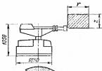
Accommodation

At first glance, the standards for placing OPS sensors are very liberal, see Fig.: no further than 4.5 m from a wall or corner and no more than 9 m between sensors. But this was done only for the convenience of configuring a specific OPS, but in fact the placement of sensors is a delicate matter.
Firstly, when placing them on walls, there must be at least 0.2 m to the ceiling, otherwise the sensor may end up in a smoke pocket and give a false alarm. Have you seen smoky rooms? It's most smoky there top corners. Secondly, with beams on the ceiling, the sensors need to be placed on their lower surfaces, and not on the sides or in the space between the beams, for the same reason.
And finally, the sensor does not survey the entire hemisphere, and its sensitivity depends on the distance to the source of danger. The controlled area is in the form of a circle in empty room depends on the ceiling height like this:
- Up to 3.5 m – up to 85 sq. m.
- 3.5-6 m – up to 70 sq. m.
- 6-10 m – up to 65 sq. m.
- From 10 m – up to 55 sq. m.
By flame:
- Up to 3.5 m – up to 25 sq. m.
- 3.5-6 m – up to 20 sq. m.
- 6-9 m – up to 15 sq. m.
- Over 9 m – not controlled; the fire will become a fire before the detector is triggered.
“Before” in front of the area means that this is the maximum achievable value - in empty room with proportions in terms of 3/4. Accurate calculation of the location of sensors in habitable rooms requires computer modeling or the eye of an experienced specialist. If the alarm system is done independently without output to the security console, then we can assume that one sensor in the living room “sees” below a square with side L equal to the ceiling height of up to 4 m. The outermost sensors should be placed at half this distance from the nearest wall, and the intermediate ones – at a distance L from each other. In long and narrow rooms, the main consideration is the distance between the sensors.
Example: corridor in Khrushchev 1.75x4 m; ceiling height - 2.5 m. Two sensors are needed, located 1.75/2 = 0.875 from the end walls. In the bedroom of the same Khrushchev building 2.5x4.5 m, two sensors are also needed 1.25 m from the end walls.
Connection

Fire alarm sensors are connected strictly according to their instructions. The beam loop always ends with a termination resistor R. Its value is indicated in the instructions for the control panel. Default R=470 ohms, but ratings of 680 ohms or 910 ohms may be required. Let us explain in more detail only two frequently requested points.
First– inclusion of five-terminal IP-212 sensors, which have proven themselves, in a two-wire loop. How to do this is shown in the figure on the left.

Second– connection of conventional sensors with one terminal block. The cable wires must enter/exit the terminal block in a MIRROR way, as shown in Fig. on right.
Third– sensors with two terminal blocks. The left block is for the CABLE, which is connected according to the instructions or as described. But the right one should be dealt with before purchasing: it is intended for autonomous activation of the SPU; Some of the most common circuits of such sensors are shown in the last figure.
If the contacts of the loop (terminals 1-4) and the SPU (terminals 6-8) are electrically separated, as in the rightmost position, then you need to find out the permissible voltage and current or power of the SPU. If the contact is common, as in the other three positions, then the voltage is 12 V at a current of up to 200 mA, and it will go to the SPU from the loop, i.e. load the sensor with light bulbs, bells, etc. you can’t - the control panel will fail.