A rectifier diode is a device that conducts current in one direction only. Its design is based on one pn junction and two outputs. The rectifier diode changes the alternating current to direct current. In addition, rectifier diodes are widely practiced in electrical circuits for multiplying voltage, circuits where there are no strict requirements for signal parameters in time and frequency.
- Principle of operation
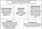
- Basic device parameters
- Rectifier circuits
- Impulse devices
- Imported appliances
Principle of operation
The principle of operation of this device is based on the features p-n junction... Near the junctions of two semiconductors, there is a layer in which there are no charge carriers. This is the locking layer. His resistance is great.
When a certain external alternating voltage is applied to the layer, its thickness becomes smaller, and subsequently disappears altogether. The current increasing in this case is called direct. It runs from the anode to the cathode. If the external alternating voltage has a different polarity, then the blocking layer will be larger, the resistance will increase.
Varieties of devices, their designation
By design, there are two types of devices: point and plane. In industry, the most common silicon (designation - Si) and germanium (designation - Ge). The first working temperature above. The advantage of the latter is a low voltage drop with forward current.
The diode designation principle is an alphanumeric code:
- The first element is the designation of the material from which it is made;
- The second defines the subclass;
- The third denotes work opportunities;
- The fourth is serial number development;
- Fifth - designation of sorting by parameters.
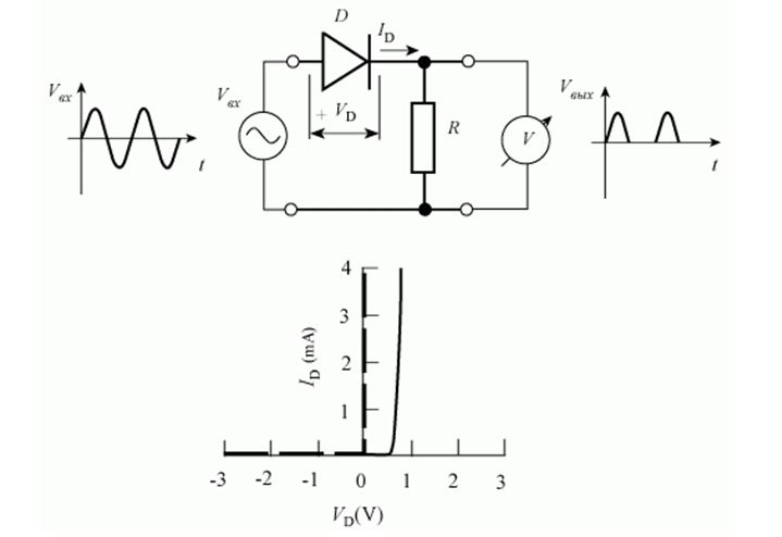
The current-voltage characteristic (VAC) of the rectifier diode can be represented graphically. The graph shows that the I - V characteristic of the device is nonlinear.
In the initial quadrant of the current-voltage characteristic, its direct branch reflects the highest conductivity of the device when a direct potential difference is applied to it. The reverse branch (third quadrant) of the I – V characteristic reflects the situation of low conductivity. This occurs when the potential difference is reversed.
Real current-voltage characteristics are subject to temperature. With increasing temperature, the direct potential difference decreases.
From the graph of the current-voltage characteristic, it follows that with low conductivity, no current passes through the device. However, at a certain magnitude of the reverse voltage, an avalanche breakdown occurs.
![]()
The CVC of silicon devices differs from germanium ones. I - V characteristics are given as a function of different temperatures. environment... The reverse current of silicon devices is much less than that of germanium devices. It follows from the I - V characteristics that it increases with increasing temperature.
The most important property is the sharp asymmetry of the I – V characteristic. Forward bias - high conductivity, reverse - low. It is this property that is used in rectifiers.
Analyzing the instrument characteristics, it should be noted: such quantities as the rectification coefficient, resistance, and capacitance of the device are taken into account. These are differential parameters.
The rectifier ratio reflects the quality of the rectifier.
To save on electricity bills, our readers recommend the "Electricity Saving Box". Monthly payments will be 30-50% less than they were before using the economy. It removes the reactive component from the network, as a result of which the load and, as a result, the current consumption are reduced. Electrical appliances consume less electricity, and the costs of paying for it are reduced.
The straightening factor can be calculated. It will be equal to the ratio of the forward current of the device to the reverse. This calculation is acceptable for an ideal device. The rectification factor can reach several hundred thousand. The larger it is, the better the rectifier does its job.
Basic device parameters
What parameters characterize the devices? The main parameters of rectifier diodes:
- The highest value of the average forward current;
- Highest allowable reverse voltage value;
- The maximum permissible frequency of the potential difference at a given forward current.
Based on the maximum value of the forward current, rectifier diodes are divided into:
- Devices low power... They have a forward current value of up to 300 mA;
- Rectifier diodes of average power. Direct current range from 300 mA to 10 A;
- Power (high power). The value is more than 10 A.
There are power devices, depending on the form, material, type of installation. The most common ones are:
- Medium power devices. Their technical specifications allow you to work with voltages up to 1.3 kilovolts;
- Powerful, high-power, capable of passing currents up to 400 A. These are high-voltage devices. There are different housings for the performance of power diodes. The most common are pin and tablet types.
Rectifier circuits
Connection diagrams power devices are different. To rectify the mains voltage, they are divided into single-phase and multi-phase, half-wave and full-wave. Most of them are single phase. Below is the design of such a half-wave rectifier and two voltage graphs in a timing diagram.
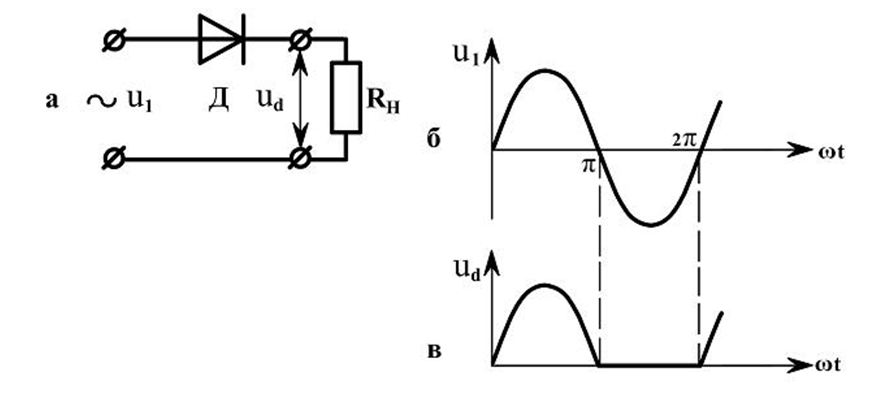
AC voltage U1 is applied to the input (Fig. A). On the right side of the graph, it is represented by a sinusoid. The diode is open. A current flows through the load Rн. With a negative half-cycle, the diode is closed. Therefore, only a positive potential difference is applied to the load. In fig. its time dependence is reflected. This potential difference is valid for one half cycle. This is where the name of the circuit comes from.
The simplest full-wave circuit consists of two half-wave circuits. For such a rectification design, two diodes and one resistor are sufficient.
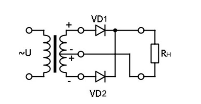
Diodes only pass a positive wave alternating current... The disadvantage of the design is that in a half-period, the variable potential difference is removed from only half of the secondary winding of the transformer.
If four diodes are used instead of two, the efficiency will increase.
Rectifiers are widely used in different areas industry. The three-phase device is involved in car generators... And the use of the invented alternator contributed to the reduction in the size of this device. In addition, its reliability has increased.
In high-voltage devices, high-voltage poles are widely used, which are composed of diodes. They are connected in series.
Impulse devices
An impulse device is called a device in which the transition time from one state to another is short. They are used to work in impulse circuits. Such devices differ from their rectifier analogs in small containers p-n transitions.
For devices of this class, in addition to the parameters indicated above, the following should be attributed:
- Maximum pulse forward (reverse) voltages, currents;
- Forward voltage setting period;
- Reverse resistance recovery period of the device.
Schottky diodes are widely used in high-speed pulse circuits.
Imported appliances
The domestic industry produces a sufficient number of devices. However, today imported ones are most in demand. They are considered to be of better quality.
Imported devices are widely used in TV and radio circuits. They are also used to protect various devices with incorrect connection (wrong polarity). The number of types of imported diodes is diverse. A full-fledged alternative replacement for them with domestic ones does not yet exist.
There are many devices and devices that convert electrical current. We propose to consider what high-power and medium-power rectifier diodes are, their principle of operation, as well as characteristics and application.
Description of rectifier diodes
A high and medium power (microwave) rectifier diode is a device that allows electric current only move in one direction, it is mainly used to operate a specific power source. Rectifier diodes can handle higher currents than conventional conductors. As a rule, they are used to convert alternating current into direct current, the frequency of which does not exceed 20 kHz. The scheme of their work is as follows:
Photo - The principle of operation of a rectifier diode
Many electrical devices need these discrete components because they can act as integrated circuits. Most often, high-power rectifier diodes are made of silicon, due to which their PN-junction surface is quite large. This approach provides excellent current transfer while ensuring that there are no shorts or surges.
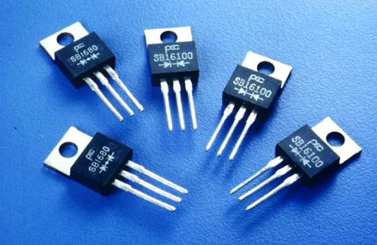
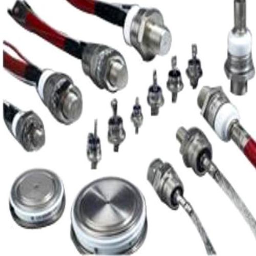
Photo - Rectifier diodes
Silicon semiconductor rectifiers, tube thermionic diodes are made using compounds such as copper oxide or selenium. With the introduction of semiconductor electronics, vacuum tube rectifiers with metal base are outdated, but their counterparts are still used in audio and television equipment. Now, to power devices from very low to very high currents, semiconductor diodes of various types are mainly used (high-speed blocks, foreign germanium devices, domestic devices tablet design, Schottky diodes, etc.).
Other devices that are equipped with control electrodes, where a simpler rectification method or an alternating output voltage is required (as an example, for welding machines) use more powerful rectifiers. These can be silicon or germanium devices. These are thyristors, zener diodes, or other controlled switching solid state switches that function like diodes, passing current in only one direction. They are used by industrial electronics and are widely used in electrical engineering, welding or power transmission control.
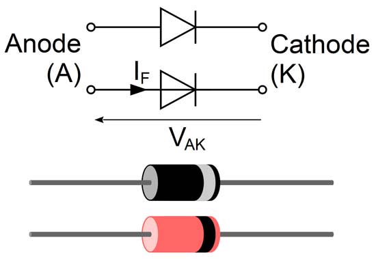
Photo - Rectifier diode and cathode with anode
Types of standard rectifiers
There are various power rectifier semiconductor diodes, depending on the type of mounting, material, shape, number of diodes, and the level of the passed current. The most common are:
- Medium power devices that can transmit a current of 1 to 6 amperes. At the same time, the technical parameters of most devices say that such diodes can change the current from a voltage to 1.3 kilovolts;
- Rectifier diodes of the maximum series can pass currents from 10 Amperes to 400, they are mainly used as ultra-fast converters to control industrial activities. These devices are also called high voltage devices;
- Low frequency diodes or low power.
Before you buy any devices of this type, it is very important to choose the right basic parameters of the rectifier diodes. These include: characteristics of the I - V characteristic (maximum reverse current, maximum peak current), maximum reverse voltage, forward voltage, case material and average rectified current
We provide a table where you can choose the type of diode, depending on your needs. These specifications may change at the request of the manufacturer, so check the seller's information before buying.
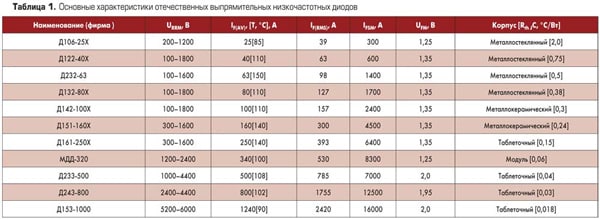
Photo - Table of low-frequency diodes
Imported (foreign) rectifier diodes (type KVRS, SMD):
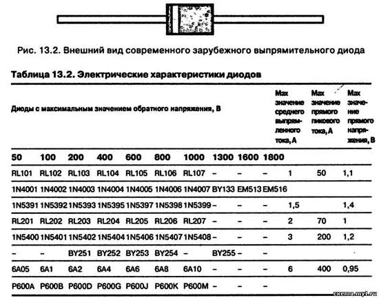
Photo - Table of imported diodes
Data about power or high frequency diodes:
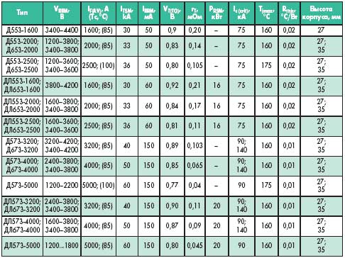
Photo - Power diodes
Rectifier switching circuits are also different. They can be single-phase (such as automotive and avalanche diodes) or multi-phase (three-phase are considered the most popular). Most low power rectifiers for domestic equipment single-phase, but three-phase is very important for industrial equipment... For generator, transformer, machine tools.
But at the same time, six diodes are used for an uncontrolled three-phase bridge rectifier. Therefore, it is often referred to as a six-diode rectifier. Bridges are considered to be impulse and are capable of normalizing and rectifying even unstable currents.
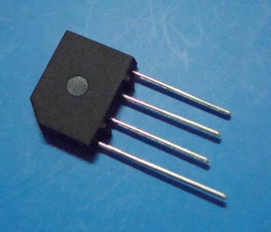
For low-power devices ( charger) double diodes, connected in series with the anode of the first diode, are also connected to the cathode of the second, and are made in a single housing. Some commercially available dual diodes have all four terminals available and can be customized to suit your needs.
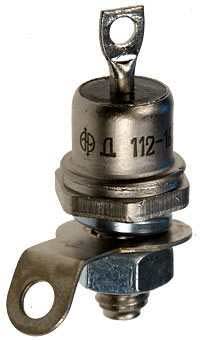
Photo - Medium power rectifier diode
For higher power, one discrete device typically uses each of the six diodes in the bridge. It can be used for both surface equipment and to control more complex devices. Often, six-diode bridges use limiting circuits.
Video: The principle of operation of diodes
Rectifier diode marking
Depending on the design and purpose, rectifier diodes are marked as follows:
Based on such data, we have the following decryptions:
КД - silicon pulse or rectifier diode;
KC - rectifier-type silicon blocks.
Before you buy rectifier diodes in Kharkov, Moscow and any other cities, be sure to check the reference characteristics with sales consultants.
A rectifier diode is a semiconductor-based diode that is designed to convert alternating current to permanent. True, the scope of application of these radio components is not limited to this function: they are used for switching, in high-current circuits, where there is no strict regulation of the time and frequency parameters of the electrical signal.
Classification
In accordance with the value of the forward current, which is the maximum allowable, the rectifier diode can have low, medium and high power:
- small - direct current is rectified up to 300 mA;
- rectifier diodes of average power - from 300 mA to 10 A;
- large - more than 10 A.
Germanium or silicon
According to the materials used, they are silicon and germanium, but more wide application found silicon rectifier diodes due to their physical properties.
They have reverse currents several times less than in germanium ones, while the voltage is the same. This makes it possible to achieve in semiconductors a very high value of permissible reverse voltages, which can be up to 1000-1500 V. In germanium diodes, this parameter is in the range of 100-400 V.
Silicon diodes are capable of maintaining efficiency in the temperature range from -60 ºС to +150 ºС, while germanium diodes are only able to maintain performance in the temperature range from -60 ºС to +85 ºС. This is because when the temperature rises above 85 ºC, the number of formed electron-hole pairs reaches such values that the reverse current sharply increases, and the rectifier stops working efficiently.
Manufacturing technology
The rectifier diode by design is a semiconductor crystal plate, in the body of which there are two regions with different conductivity. This is the reason that they are called flat.
Semiconductor rectifier diodes are made as follows: on the region of the semiconductor crystal with n-type conductivity, melting of aluminum, indium or boron occurs, and phosphorus is melted on the region of the crystal with p-type conductivity.
When exposed high temperatures these two substances are firmly fused with the semiconductor base. In addition, the atoms of these materials diffuse into the crystal to form a region with predominantly electron or hole conduction in it. As a result, a semiconductor device is formed, which has two regions with different types electrical conductivity, and a p-n-junction is formed between them. This is the principle of operation of the vast majority of junction diodes made of silicon and germanium.
Design
In order to organize protection against external influences, as well as to achieve reliable heat dissipation, a crystal with a p-n-junction is mounted in a case.
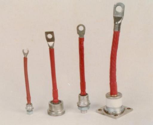
Diodes with low power are produced in a plastic case, provided with flexible external leads. Medium-power rectifier diodes have a metal-glass case already with rigid external leads. High-power parts are housed in a metal glass or cermet body.
Silicon or germanium crystals with p-n-junction are soldered to the crystal holder, which also serves as the base of the case. A body with a glass insulator is welded to it, through which one of the electrodes is output.
Low-power diodes, which are relatively small in size and weight, have flexible leads, through which they are mounted in circuits.
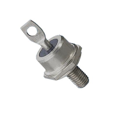
Since the currents with which medium-power semiconductors and high-power rectifier diodes work reach significant values, their leads are much more powerful. Their lower part is made in the form of a massive base that removes heat, equipped with a screw and outer surface flat shape, which is designed to provide reliable thermal contact with an external radiator.
Specifications
Each type of semiconductor has its own operating and limiting parameters, which are selected in order to ensure operation in any circuit.
Rectifier diode parameters:
- I straight max- direct current, which is the maximum allowable, A.
- U return max- reverse voltage, which is the maximum allowable, V.
- I return- DC reverse current, μA.
- U straight- direct voltage constant, V.
- Working frequency, kHz.
- Working temperature, WITH.
- P max- the power dissipated on the diode, which is the maximum allowable.
The characteristics of rectifier diodes are far from being exhausted by this list. However, they are usually sufficient to select a part.
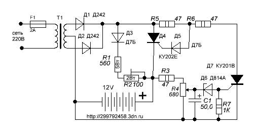
Scheme of the simplest AC rectifier
Consider how the circuit works (the rectifier diode plays in it the main role) a primitive rectifier.
Its input is supplied with mains alternating voltage with positive and negative half-periods. The load (R load) is connected to the output of the rectifier, and the diode (VD) performs the function of the element that rectifies the current.
Positive voltage half-cycles applied to the anode cause the diode to open. At this time, a direct current (I direct) flows through it, and therefore through the load (R load), which is powered by the rectifier.
Negative half-periods of the voltage applied to the anode of the diode cause it to close. A small reverse diode current (I arr.) Flows through the circuit. Here the diode cuts off the negative half-wave of the alternating current.
As a result, it turns out that through the load connected to the network (R load), through the diode (VD), a pulsating current now passes, and not an alternating current of one direction. After all, it can take place exclusively in positive half-periods. This is the meaning of AC rectification.
However, such a voltage can only supply a low power load that is powered by an AC mains and does not impose serious power requirements, for example, incandescent lamps.
The lamp will transmit voltage only when positive pulses pass, as a result of which the electrical appliance undergoes a weak flicker, having a frequency of 50 Hz. True, due to the fact that the thread is subject to thermal inertia, it will not be able to cool down completely in the intervals between pulses, which means that the flickering will be almost invisible.
If such a voltage is applied to an amplifier or power receiver, then a sound will be heard in the loudspeaker low frequency (frequency 50 Hz), which is called AC background. This effect occurs due to the fact that the pulsating current, while passing through the load, induces a pulsating voltage in it, which generates a background.
Such a disadvantage is to some extent eliminated if a filter capacitor (C filter) is connected in parallel with the load, the capacity of which is large enough.
The capacitor will be charged by current pulses during positive half-cycles, and discharged through the load (R load) during negative half-cycles. With sufficient capacitor capacitance during the time that passes between two current pulses, it will not have time to completely discharge, and therefore, the load (R load) will constantly have a current.
But even with such a relatively smoothed current, the load should also not be supplied, because it will continue to flicker, because the magnitude of the ripple (U pulse) is still quite serious.
disadvantages
The rectifier we just discussed uses only half of the AC waves to good use, so it loses more than half of the input voltage. This type of AC rectification is called half-wave, and rectifiers that use this type of rectification are called half-wave. The disadvantages of half-wave rectifiers have been successfully eliminated in rectifiers using a diode bridge.
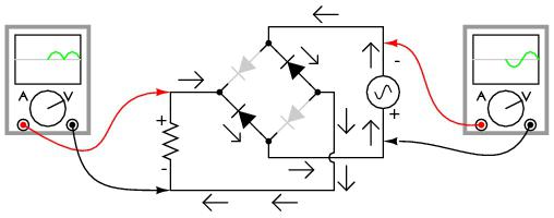
Diode bridge
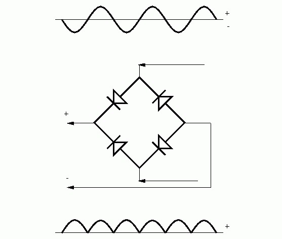
A diode bridge is a compact circuit that is made up of four diodes and serves the purpose of converting AC to DC. The bridge circuit makes it possible to pass current in each half-cycle, which favorably distinguishes it from a half-cycle. Diode bridges are produced in the form of small assemblies, which are enclosed in a plastic housing.
At the output of the case of such an assembly, there are four pins marked "+", " — " or " ~ "Indicating the purpose of the contacts. However, diode bridges are also found not in the assembly, they are often assembled directly on printed circuit board by switching on four diodes. A rectifier that runs on diode bridge, is called full-wave.