Lecture number 1. Classification of sewing machines. Main working bodies sewing machine... Sewing machine parts.
Sewing machines are very diverse in their appearance, design and kinematics. Depending on the nature of the weaving of the threads in the line, they are divided into machines shuttle and chain weave.
The following groups of machines are distinguished by purpose:
- lockstitch shuttle weave;
- straight-stitching single-thread chain weave;
- straight stitching multi-thread chain weave;
- zigzag shuttle stitch;
- overcasting machines; blind stitch machines;
- semiautomatic devices for sewing on buttons and other accessories, operational coupons, for bartacking, and short stitches;
- semiautomatic buttonhole sewing machines;
- semiautomatic devices for assembling and processing individual parts of clothing.
To designate sewing machines, there is a historically established system of simple serial numbers, somewhat modified in recent years. According to the factory classification, sewing machines are divided into classes, options and modifications. Each manufacturer established its own class designations, assigning each newly mastered machine to the next serial number... If options were developed on the basis of this machine (changes or additions of new mechanisms), then they were designated by letters, for example, machines 1, 2, 22-A, 22-B, 22-B, 26, 26-A, 51, 51-A cl ... Podolsk Mechanical Plant named after M.I. Kalinin (PMZ) of the production association "Podolskshveimash". Since 1968, it was decided to keep the designation of their classes for the previously produced machines, and to assign designations to the variants of these machines, consisting of a machine class number with the addition of a serial number, starting with the number 2.
The Orsha plant of light engineering of the production association "Promshveimash" designates its machines in a similar way: machine 97-A class. - lockstitch sewing shuttle weave; 297 cl. - with the landing of the bottom material; Class 397 - with a knife for trimming cuts of parts; 597-M class. - with a deviating needle; 697 cl. - with differential movement of materials, etc. Rostov-on-Don plant "Legmash" of the production association "Promshveimash" produces stitching and overcasting sewing machines and, depending on the nature of the work performed, as well as the purpose, classifies them by entering alphabetic and digital designations ( for example, machines 408-M, 408-AM, 508-M, 1208-A class, etc.).
Despite the fact that the digital and letter designations of sewing machines are abstract, the designations of the classes began to reflect the main provisions of the so-called basic family principle of creating sewing equipment, according to which, on the basis of basic structures machines are being developed for their variants and modifications. Modification - adaptation of a basic sewing machine to a specific operation without making structural changes. An example of a modification is the 852-1x10 machine with a line spacing of 10 mm: basic machine 852x5 cl. PMZ has a distance between the lines of 5 mm.
Domestic sewing enterprises use equipment manufactured by machine-building associations of foreign countries - the Czechoslovak association "Minerva" manufactures industrial machines that perform a zigzag line; Hungarian foreign trade enterprise exports various sewing machines; press equipment; Association "Textima" (GDR) produces industrial and household sewing machines, shuttle and chain weave. Large supplies of sewing equipment to our country are carried out by the Japanese company / Juki. "
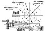
The industrial sewing machine consists of a machine head, an industrial table and an individual electric drive. The head of the sewing machine has a sleeve 2 (Fig. 1), a sleeve stand 4 and a platform 5. The sleeve 2 of the machine on the left has a frontal part 1. Rotation from the electric motor is transmitted to the flywheel 3. The distance a from the post of the sleeve 4 to the line of movement of the needle is called departure cars. This distance is determined by the size of the products that can be placed on the machine platform to the right of the needle.
Rice. 1. Appearance sewing machine and its main working bodies
For sewing shuttle or chain weaving, each sewing machine has the following main working tools:
needle- serves for puncturing materials, passing the upper thread through them and forming a loop (overflow);
thread take-up, and in chain weaving machines, the thread feeder serves to feed the thread to the needle, shuttle (looper), tightens the stitch and pulls off the reserve thread from the bobbin;
shuttle or looper in chain weaving machines - captures the loop of the needle, expands it, wraps it around the bobbin or enters it into the previous loop in chain weave machines, interweaving the threads;
material transfer mechanism(rail) serves to move materials by the length of the stitch;
foot presses the materials against the stitch plate and the bar to aid in the movement of the material.
Drawing up kinematic diagrams of sewing machine mechanisms
It is convenient to study the design of the sewing machine mechanisms, the principles of their operation and their adjustment using flat or spatial kinematic diagrams.
Under kinematic diagram mechanisms of a machine is understood as a simplified representation of the details of mechanisms for displaying the structure and conditions of transformation and transmission of influences. The symbol of parts should be performed in such a way that it reflects the design features of the part that affect the nature of the transformation of motion, or special functionality. For example, the thread take-up has two axes and a free end with an eye; its designation is similar to the connecting rod, but with a reflection of its curved shape and lug.
When drawing up a kinematic diagram, it is necessary to adhere to certain rules:
- the arrangement of parts on the diagram should correspond to their location in the machine;
- should reflect the actual relationship with other parts of the machine;
- the diagram should give an idea of the nature of the transformation of motion;
- the design features of the part that determine the adjustments in the machine (slots in the parts, joints of parts, etc.) must be indicated;
- you should not complicate the diagram with structural details of parts and details that do not affect the nature of movement, adjustments and action of mechanisms.
Spatial kinematic scheme is performed in the AYZ coordinate system where the ordinate axis of the OU is located vertically, the axis OH is held at an angle of 7 "from the horizontal upwards, and the axis OZ – at an angle of 41 ° from the horizontal downward.
Consider the kinematic diagram for the needle mechanism of the shuttle stitch sewing machine.
The construction of a diagram begins with a study of the structure of the mechanism, its parts, their location and movement in the car and the available adjustments, etc. For the needle mechanism (Fig. 2), the working body is needle 1. The needle mechanism consists of a crank 8, fixed on the main shaft 10 screw and pin. Main shaft 10 passes in a rolling bearing 9. A finger is fixed in the crank 8 6, on which the upper head of the connecting rod 11 is put on. Between the connecting rod 11 and the pin 6 inserted needle bearing 7. The lower head of the connecting rod 11 is put on the leash (lever) 3, which with the lag screw 4 connected to the needle bar 2. The cylindrical part of the leash 3 inserted into the slider hole 14. The slider is between the guides 13. Guides 13 fixed in the sleeve of the machine with screws 12. Needle bar 2 passes in two bushings (sleeve bearings) 5, which are fixed with screws in the sleeve of the machine. At the lower end of the needle bar 2 with the screw 15, the needle is fixed 1.
Since the screw fixing of the rails 13 and bushings 5 in the machine sleeve can be replaced on the kinematic diagram with shaded surfaces, then the screws in Fig. 2 are not shown. The spatial kinematic diagram (Fig. 2, c) reflects the real relative position of the parts. Main shaft 10 located horizontally, i.e. coincides with the axis OH. There is a crank at its front end. 8, connecting rod 11 and leash 3. One end of the leash 3 enters the slider 14, and the other is put on the needle bar 2. Since the needle 7 in the lockstitch sewing machine moves vertically, the position of the needle bar 2 coincides with the direction of axis 07. Screw 4 serves for adjustment, therefore, in the diagram, it is necessary, since it reflects the place of the connector of the kinematic connection between the shaft 10 and a needle 1 for height adjustment.
The flat diagram of the needle mechanism (Fig. 2, d) is simpler, but it does not make it possible to imagine a complex spatial mechanism, the movement of parts in different planes (for example, the looper mechanism in the furrier machine 10-B). Therefore, further we will use spatial kinematic schemes.
When constructing a flat kinematic diagram, all parts are projected onto a plane, in this case vertical, parallel to the plane of rotation of the crank. If this is not feasible, then other planes are located in the main one, i.e. in the one in which there is a movement of the working body of the mechanism.
The action of the mechanism according to the kinematic diagram is considered in the following sequence: they determine the position of the working body of the mechanism and the chain (chain) of parts that impart movement to the working body from the main shaft, study the process of transferring motion to the working body, starting from the main (camshaft) of the machine.
Adjustment in the machine mechanism is possible at the connection points through the tightening screws of the levers on the shafts, axles or other bearing parts. Places of adjustments are indicated by elongated lines in the lever, adjusting screws, adjusting nuts, cams, etc.

Fig. 2. Elements of the kinematic diagrams of the machine needle mechanism
b - constructive scheme
c - block diagram in space
d - block diagram on the plane
All sewing machines are composed of parts, assembly units (for example, a shuttle kit) and mechanisms. For the correct connection of parts, their orientation relative to each other and ensuring the interaction of mechanisms in the process of forming stitches and stitches, as well as a number of other functions in sewing machines, parts are used to connect parts of assembly units, to transfer rotation and to convert various types of movements.
Parts for connecting parts of assembly units. The connection of machine parts can be one-piece or detachable. With an integral rigid connection, one part cannot have any displacements relative to the other.
Detachable rigid connections made by screws, bolts, cotter pins, keys and other details are much more widespread. For example, attaching the needle with a screw provides a rigid, detachable fastening of the needle in the needle bar.
Screws can be with or without heads. They have a thread on their rod, and on top there is a slot for a screwdriver. The bolts have hex or square heads for the appropriate wrench.
Widely used in sewing machines are screws with trunnions for hinged joints that ensure the movement of one part relative to another. These screws can have cylindrical and tapered joints. The hinge screws include the center pin, which is secured with a screw. Center pins have a ground tapered end and are paired with another screw or pin to hold the shafts .
Details for transmitting rotational motion. Plain and rolling bearings (ball bearings and needle bearings) are used to support rotating shafts or axes in sewing machines.
To transmit rotation to parallel shafts located on great distance from each other, use belt and gear-belt drives. On parallel shafts, gear drums are fixed, on which the toothed belt is put on . To transmit rotation to parallel shafts, cylindrical helical and spur gears with external and internal gearing are used. The transmission with internal gearing does not increase the size of the sub-assembly, i.e. it is compact.
Details for transforming movements. A crank mechanism is used to convert rotary motion into translational motion in sewing machines. It consists of a crank attached to the end of the shaft and making a rotational movement with it. A connecting rod is put on the crank pin. It has two heads and a body and is the main element in transforming the movement of one kind into the movement of another. The pin of the needle bar driver is inserted into the hole in the lower head of the connecting rod.
An eccentric transmission is used in sewing machines to convert rotary motion into oscillatory motion. Such a transmission consists of an eccentric (cylindrical part), the center of which is offset relative to the center of the shaft.
Lecture number 2. Properties of the shuttle stitch. The principle of forming a lockstitch. Classification of machine needles and methods of their installation. Refueling sewing machines
1. PROPERTIES OF HOOK STITCH
Double thread shuttle stitch is formed from two threads - upper A and lower B , which should be intertwined between the materials to be sewn. Upper thread A called needle, lower B - shuttle, since it comes from the bobbin inside the shuttle set, the distance between the two needle punctures is called the stitch length.
The shuttle stitch is difficult to open and strong enough to tear both along and across the seam. The shuttle stitch is less stretchable than the chain stitch and is widely used for the manufacture of various types of clothing and linen.
When determining the consumption of threads for the formation of a shuttle stitch, the utilization factor is taken into account, which on average is 1.2-1.7. So, with a utilization factor of 1.5, a 10 cm long seam consumes: 15 cm of the upper and 15 cm of the lower thread. The wear rate depends on the stitch length, thickness and properties of the materials to be sewn, the degree of thread tension and other factors. For the formation of a shuttle weave of threads, more complex mechanisms are required than for a chain. For example, a shuttle set consists of a large number parts and requires constant cleaning and lubrication. The presence of a bobbin in the hook set reduces the utilization rate of the machine: during a change, the bobbin can be replaced 70 - 80 times. For example, when sewing step cuts of trousers on a machine 97-A class. OZLM. re-threading the bobbin takes 3-5% of the working time.
2. THE PRINCIPLE OF FORMATION OF THE HOOKBOOK
The intertwining of the threads during the formation of the shuttle stitch can be done with the help of an oscillating, oscillating or rotating shuttle. The most widespread machines are machines with rotating shuttles, therefore, below we will consider the principle of stitching on a machine with a rotating shuttle.
Upper thread from spool 5 (Fig. 3, a) or the bobbins are encircled between the washers 3 tension regulator, inserted into the eye of the thread take-up 4 and threaded into the eye of the needle 2. Needle 2 pierces the material, guides the upper thread through it and descends to the lower end position. When lifted, the needle forms a loop from the thread, which is captured by the nose of the shuttle. The needle (Fig. 3, b) begins to rise up, the nose of the shuttle 7, capturing the loop of the upper thread, expands it. Thread take-up 4, moving down, feeds the thread to the shuttle. The loop of the upper thread is looped around the bobbin by the hook (fig. 3, c ).
When the loop of the upper thread is circled at an angle greater than 180 (Fig. 3, d), the Thread take-up take-up will tighten the stitch. Rail 6 will move the material by the stitch length.
Shuttle (Fig. 3, e) makes an idle run, and at this time other working parts of the machine (needle, rail and thread take-up) finish their work.
Oscillating shuttle machines operate on the same principle, which are less common in the garment industry due to the uneven movement of the shuttle.

Rice. 3. The principle of formation of the shuttle stitch
3. CLASSIFICATION OF MACHINE NEEDLES ACCORDING TO GOST 22249-82 E
All machine needles are used to pierce materials, pass the thread threaded into the eye of the needle through it and form a loop of the required size, and then remove the excess part of the thread from the material and tighten the stitch. The machine needles have flask for attaching the needle in a needle holder or needle bar, rod and point for puncturing materials. To form a loop along the point and the rod, there is short groove, and on the opposite side long groove to protect the upper thread from chafing. Ear the needle is used to thread the upper thread into it.
GOST 22249 - 82 E contains digital designations of the needles, depending on the shape of the section of the rod, the shape of the sharpening of the tip and the peculiarities of the manufacture of the flask. Taken into account: the diameter of the flask, its length, the length of the entire needle, the length from the upper edge of the tab to the end of the flask, the position of the grooves on the rod, etc.
In addition to special digital designations all machine needles are numbered - this is the thickness of the rod in hundredths of a millimeter. The sewing industry uses needles of numbers from 60 to 210. For example, sewing needles, machines 1022-M class. are designated by the number 0203.

Rice. 6. Right and left twist of thread

Fig 7. Definition of thread twist
The designation A-75 indicates that the needle was produced by the Artinsky Mechanical Plant. Household sewing machine needles have a longitudinal flattened on the bulb to facilitate correct insertion of the needle into the machine.
Before sewing the materials, you need to select the threads in accordance with the requirements of the sewing machine passport and, depending on the threads, select the needles.
When choosing threads, pay attention to the direction of twist, which is left (S) and right (Z) (fig. 6). This is due to the fact that in some classes of sewing machines, threads will unwind and lose their strength in the process of weaving, in other classes, threads of such a twist are quite acceptable. For these reasons, the selection of threads must be made in accordance with the requirements of the sewing machine passport.
To determine the direction of the twist, the thread is clamped between the thumb and forefinger of the right and left hand (Fig. 7), with the thumb of the right hand relative to the index finger rolled away from itself, i.e. rotating it counterclockwise. If the strands of the thread are twisted, then this is the thread of the right twist, if untwisted, it is the left twist.
Lecture number 3. The device and operation of the mechanism of the needle and thread take-up of sewing machines
Needle mechanism. The mechanism of the needle in the shuttle stitch sewing machine is designed to convert the rotational, movement of the main shaft of the machine into reciprocating movements of the needle along a straight path.
The main parameter of the needle mechanism is the total needle travel, i.e. moving it from the extreme upper to the extreme lower position. The greater the total needle stroke, the thicker the fabric the machine can grind.
The mechanism of the needle, depending on the method of transformation, movement and the presence of parts, has the following types: crank-connecting rod (Fig. 8, a ), crank-slider (Fig. 8, b), axial (Fig. 8, c ), disaxial (Fig. 8, d), articulated multi-link (Fig. 8, d ) and many others (crank-rocker, cam in a class 25 car, etc.).
The crank mechanism received the name due to the presence of a crank 1 and a connecting rod in its design 2. Household sewing machines have such a mechanism. On high-speed sewing machines, crank-slide mechanisms are used, in which on a leash 3 the slider is located 6. Slider eliminates needle bar reversal 4 when the machine is running.

Rice. 8. Mechanisms of needles
In the operation of the needle mechanism, it is necessary first of all to pay attention to the position of the needle in height. In the uppermost position, the point of the needle should not protrude below the sole of the presser foot in its up position. In the lowest position, the needle should be at such a height that, when lifting, it forms a loop and brings it to the trajectory of the shuttle nose. When raising the needle from the lowest position to a height S = 1.9 ... 2.5 mm, necessary for the formation of a needle loop (looping stroke), the nose of the shuttle that came out to capture the loop must be higher than the upper edge of the eye of the needle by c = 1 ... 2 mm. Typically, on machines with a rotating hook, the eye of the needle should protrude (at its lowest position) by half due to the front of the bobbin holder.
Adjustment of the needle height in the mechanism is performed after loosening the leash fastening screw 3 on the needle bar 4 needle bar offset 4 together with the needle 5 up or down, focusing on, meeting the requirements for gripping the needle loop.
Thread take-up or thread feed mechanism
The thread take-up mechanism in the lockstitch sewing machine imparts the necessary movement to the thread take-up and serves to feed and tighten (pull) the needle thread during the formation of the lockstitch.
In sewing machines, the following types of thread take-up mechanisms are used: cam (Fig. 9, a), crank-yoke (Fig. 9, b), crank-rocker (Fig. 9, c), rotating shaped or cam (Fig. 9, d )
The thread take-up mechanism is usually structurally linked by the needle mechanism. Both mechanisms have a single driving link - a crank. In household sewing machines operating with a shaft rotation frequency of up to 1200 min "1, cam (drum) needle thread take-ups are used (see Fig. 9, a), consisting of cam 7, thread take-up lever 2 and axis 3.
In industrial sewing machines, crank-rocker arms are used (see Fig. 9, b) thread take-ups. Their design includes a crank 8, thread take-up lever 7 (rocker arm), link 6, axle 5 and double-crank pin 4.
In sewing machines with a vertical axis of rotation of the shuttle, crank-yoke thread take-ups are used (Fig. 9, v), which consist of a crank 12, of the thread take-up lever 11, axes 10, backstage 9, connecting rod 13 and a finger. Unlike crank-yoke thread take-ups, crank-yoke thread take-ups more quickly release the thread, that is, they pass from the extreme upper to the extreme lower position in a short time of turning the main shaft, which contributes to the timely entry of the thread into the needle and shuttle and the reduction of the needle loop and its tightening stitch.
For high-speed sewing machines (rotation speed over 5000 min "1), rotary shaped thread take-ups made in the form of a disk are used 14 special shape, fixed on a disk, which is attached with two 15 screws to the pin 16.
Only with a rotating type of thread take-up is the timing of the feeding and tightening of the stitch adjusted. To perform the adjustment, it is necessary to loosen the screw 15 and turn the disc 14. If the disc is turned in the direction of rotation of the main shaft, the thread take-up will operate earlier. When making the adjustment, check that there is no sharp tension or re-gripping of the needle thread after the loop comes off the nose of the cover plate-staple in the shuttle device.

Rice. 9. Thread take-up mechanisms in lockstitch sewing machines
The 97-A uses a shaped rotating type of thread take-up mechanism (fig. 10). The thread take-up 7 along the hole 2 is put on the axis 3 of the finger 5 of the crank 4 and through the sector 6 with screws 7 it is attached to the tide of the finger 5. A knife is fixed to the front board of the machine sleeve with a screw and a nut to cut the thread in case of its breakage and eliminate its winding on the thread take-up profile 8 7.
The mechanism adjusts the timing of the thread tightening in the stitch by turning the thread take-up 8 after loosening the screws 7. When the thread take-up 8 is turned counterclockwise, the stitch is tightened earlier. A delay in tightening the stitch may cause the needle loop that has been thrown off the hook to re-catch.

Rice. 10.the thread take-up mechanism
Lecture number 4. The structure and operation of the shuttle mechanism. Shuttle set device

Rice. 11. The shuttle mechanism of the 97-A class machine.
The 97-A adopts a center-bobbin uniformly rotating type of shuttle mechanism. On the main shaft (fig. 11). 6 is fastened with two screws toothed drum 7. On the lower camshaft 9 is fixed the lower toothed drum 8. A toothed belt 5 is put on both drums. To eliminate the axial displacement of the belt, spring rings are also put on the drums. The camshaft 9 rotates in ball bearings and in two bushings. At its left end, gear 10 with internal teeth is fixed with two screws. Gear 10 meshes with small gear 4 and forms a gear train with a gear ratio of 1: 2. The gear 4 has a single design with the shuttle shaft 3. The shuttle shaft 3 rotates in two bushings, pressed into the bushing 11, which is fixed with a screw in the machine platform. The shuttle 1 is installed on the left end of the shaft 3 and fixed with two screws 2.
The hook 7, through the toothed belt and gear transmission, receives rotation in the same direction as the machine pulley, but in one revolution of the main shaft it makes two revolutions.
The timing of the approach of the hook nose 7 to the needle is adjusted by turning it after loosening the screws 2. When the needle is lifted from the lowest position to the distance S = 1.9 ... 2.1 mm, the hook nose should come out on the trajectory of the needle movement.
The gap between the nose of the shuttle 7 and the needle is adjusted after loosening the screw securing the sleeve 11 and axial displacement of the sleeve 11 together with the shuttle 7. Gap D = 0.05 ... 0.1 mm.
The amount of oil supplied to the shuttle is regulated by screw 12. When screw 12 is removed, the oil supply to the shuttle increases. Checking the supply of lubricant to the shuttle should be carried out at the maximum number of revolutions of the main shaft, for which it is necessary to put a sheet of paper under the shuttle and hold it motionless for 15 seconds. If there are two scattered stripes of oil approximately 1 mm wide on the paper, the oil flow to the hook is normal.
Shuttle design
Let us consider the design of a shuttle set evenly rotating with a horizontal axis of rotation (Fig. 12). Using screws 10 (two or three), the bobbin case 13 is attached to the shuttle shaft of the machine (not shown in Fig. 3.8). The body 13 has a nose 9 for gripping the needle loop. The nose 9 during the operation of the device in the machine must be pointed and not have burrs. The upper plate 11 is attached to the body 13 of the device with screws 12. The front and side surfaces of the plate 11 are the same as lateral surfaces spout 9 must be carefully ground and polished. In the body 13 there is a groove 14, which includes the belt 16 of the bobbin holder 18. From falling out of the bobbin holder 18 from the body 13 a half-ring bracket 15 is used, fixed with three screws 7 on the body 13. The nose 8 of the half-ring-staple 15 must be polished, since the needle loop passes from it when it comes out of the shuttle.
Girdle 16 bobbin holder 18 open at the top. Its ends along the ends at the point of rupture along the side edges, as well as other surfaces of the parts with which the thread contacts during the formation of the stitch, must be polished. Front of the bobbin holder 18 has a groove 17, which includes a protrusion 3 latches 7. If fitted in the bobbin holder 18 two grooves 17 the second is used to interact with the drain. At the top of the front of the bobbin holder 18 there is a groove 6, in which includes the protrusion 5 of the adjusting pin 21. Positioning finger 21 fixed in the machine body with a screw 20. In the center of the bobbin holder 18 there is a center pin 19 for locating and securing the bobbin case 23.
The bobbin case body has a milled groove on the front 29, which includes the latch 1. Latch 1 is hinged (using a finger 30) connected to movable plate 2 . A screw is installed on the latch 7 (to prevent it from falling out of the bobbin case) 4. Latch 1 is fixed in the groove of the center pin 19 with a spring 31, which is installed in the hole 24 bobbin case. Spring 28 for adjusting the tension of the shuttle thread is fixed with an adjusting 20 and regulatory 27 screws on the side of the case 23 cap.
Bobbin 22 fits on the cylindrical hollow shaft 25 of the bobbin case 23.

Rice. 12. Rotary hook of the sewing machine
Lecture number 5. Design and operation of the tissue engine mechanism. Knots of vertical, horizontal movement of the rail and regulator of stitch length and bartack

Rice. 13. Mechanism for moving materials: the unit of horizontal and vertical movement of the rack, the mechanism of the reverse motion of the machine.
The machine uses a rack and pinion type fabric motor mechanism, consisting of presser foot lifting, advance (vertical and horizontal), adjustment and reverse gear rack.
Material advancement mechanisms. When forming a lockstitch, the material can be moved in one of three ways:
- a rack conveyor and its varieties, when the transfer of material is provided by a rack;
- disk (roller), when material is transported by disks with corrugated surfaces;
- a frame fixing the material between two plates and performing movement within the frame size.
The disk (roller) conveyor is used in sewing machines for processing leather and fur products, as well as for performing auxiliary actions in specialized sewing machines (transporting tape, lace, etc.).
The frame is used in machines that sew according to a given program (buttonholes, bartacks, etc.), as well as in universal programmable machines when sewing embroidery, monograms, etc.
Node for vertical movement of the rail. On the lower camshaft 26 (Fig. 13), the lifting eccentric 34 is fixed with two screws, and the connecting rod head 33 is put on it. A needle bearing is inserted between the connecting rod 33 and the eccentric. The second head of the connecting rod 33 through the hinge screw 30 by means of the nut 32 is connected to the rocker arm 31, which is fixed to the lifting shaft 43 by the tightening screw 29. The shaft 43 is centered by the pins 27 and 45 fixed by the screws 28 and 44 in the machine body. At the front end of the shaft 43, there is a lift arm 42. The finger fixed in the lever 42 enters the axial hole of the slider 41, which is located in the guides of the fork lever 47. A rack 46 is fixed on the fork lever.
The rotation of the eccentric 34 causes oscillatory movements of the connecting rod 33 and with the help of the rocker arm 31, the shaft 43 and the lever 42 with the slide 41 moves the rack 46 in vertical plane.
The unit for horizontal movement of the rail. On the camshaft 26, the advancement eccentric 36 is made in one piece with the lift eccentric 34. A fork connecting rod head 37 is put on the advancement eccentric 36. A needle bearing is inserted between the connecting rod 37 and the eccentric. An axle 16 is inserted into the rear head, made in the form of a fork, which also forms a hinge connection with the bifurcated head of the connecting link 13 and is rigidly connected with the rocker arm 38 using a screw 15. The lower head of the rocker arm 38 is threaded through the axle 39, the front part of which is put on on the lower head of the rocker arm 40, and its remote end is rigidly connected by means of a screw to the lever 35. The upper head of the rocker arm 40 is pivotally connected through a pin 48 to the machine body. Stud 48 is secured with a screw in the machine platform. The upper head of the lever 35 with the screw 17 is fixed on the intermediate shaft 18 of the stitch length adjustment unit.
The connecting link 13 with the distal head is pivotally connected through the screw 11 with the rocker arm 10, which is fixed to the advance shaft 8 by the tightening screw 9. The advance shaft 8 is held by two pins 12 and 2 in the machine body. Studs 12 and 2 are fixed, respectively, with screws 14 and 1 in the machine platform. At the front end of the shaft 8 there is a vertical frame 7, in which the lever-fork 47 is centered using pins 6 and 3. Pins 6 and 3 in frame 7 are fixed with screws 5 and 4.
Rotation of the eccentric 36 causes oscillatory movements of the connecting rod 37, which are converted by means of the rocker arm 38 into the reciprocating movements of the axis 16. When stitching with a stable stitch length, the oscillation axis 39 of the rocker arm 38 is stationary. From the axis 16, the oscillatory movements are communicated to the rocker 10 through the connecting link-fork 13. The rocker 10, fixed on the propel shaft 8, and the frame 7 perform reciprocating movements that move the rack 46 in the horizontal direction.
Unit for adjusting the stitch length and performing a bartack (reverse stroke of the rack)... To adjust the stitch length and perform the reverse stroke of the rack (this allows you to perform a bartack on the line) in the machine 97-A, the intermediate shaft 18 is connected to the two-arm lever 22 through the lever 25 and the pull rod 21. The handle 24 is fixed at the end of it coming out of the body. To return the handle 24 in the uppermost position after performing a bartack in the stitching on the intermediate shaft IS is fixed by means of screws the adjusting ring 20. One end of the spring 19 is inserted into the hole of the adjusting ring 20, and the other end abuts against the machine platform.
Changes in the distance of material transportation (adjustment of the stitch length) are performed by changing the position of the axis 39. The more the axis deviates from the plane drawn through the axis 16 and the hinge screw 11 in the middle position of the rack 46, the longer the stitch length. When the axis 39 reaches this plane, the stitch length is zero, and with further counterclockwise movement, the movement of the staff is converted into the opposite. The position of the lever 22 is fixed with a nut 23.
The stitch length in the 97-A machine is adjusted by turning the knurled nut 23 (see fig. 13) located in the handle 24 of the regulator. When tightening the nut 23 the handle moves downward and the stitch length decreases.
Rise height 46 over the throat plate is adjusted by turning the lever 42 after loosening the screw 29 rocker arm mounts 31 to the lift shaft 43.
Reiki position 46 in the slot of the needle plate in the transverse direction is set by loosening the screws 5 and 4 fastening the studs 6 and 3 on the frame 7 promotion shaft 8 and with further displacement of the fork lever 47 with rail 46.
Correspondence of the stitch length to the index on the sleeve is achieved by setting the "0" position with the handle 24 and after loosening the screw 17 by turning the lever 40 with axis 39 and bringing it to the plane of the axis 16 and screw 11. Rail 46 must not move horizontally over the throat plate.
Lecture number 6. The device and operation of the mechanism of the foot

Figure 14. Presser foot assembly
The hinge foot 1 is attached by a screw 2 to a rod 22 moving in a sleeve 21, which is pressed into the sleeve of the machine. At the upper end of the sleeve 21 is a bracket 20, its flat protrusion enters the vertical slot 4 of the sleeve. A sleeve 17 is fixed on the rod 22 with a screw 18, to which a pusher is attached to release the thread when the foot is raised. The flat protrusion on the sleeve 17 is also inserted into the vertical slot 4 of the sleeve. The protrusion on the sleeve 17 does not allow the presser foot 1 to rotate around the axis of the rod 22. From above into the rod 22 nested ball 16, pressed by the leaf spring 15, put on the right end on the screw 14. The adjusting screw acts on the spring 15 from above 9. Bottom on the bracket ledge 20 the cam can be affected 3, rigidly pressed on the horizontal axis 19. At the right end of the axle 19 the lever 23 for manual lifting of the presser foot 1 is fixed. When the cam 3 is turned, it through the pusher (not shown in Fig. 14) and the rod squeezes the tension regulator plate and releases the needle thread.
For knee lifting of the presser foot to the bracket 20 attached by a hinge screw lower link head 5. Upper link head 5 is attached to the stem 6, which is welded to the arms 7 (11) and 11. The arm 7 (11) is held by the pivot screws 8 and 10. The upper end of the rod is inserted into the right protrusion of the lever 11 13 and secured with an adjustable pin 12. Lower end of rod 13 passes through a hole in the platform of the machines, a spring is put on the bottom of the rod 24 and washer 25. Washer 25 is also secured with an adjustable pin.
Pressing the lever to lift the knee traction 13, rising, turns the lever 11 counterclockwise and through link 5, the bracket 20 and the clutch 17 lifts the rod 22, and with it the presser foot 1.
The pressing force of the foot 7 (see Fig. 3.36) of the material is regulated by the adjusting screw 9. When screwing in the screw 9, the pressing force of the material by the foot 1 increases.
Timeliness of raising and advancing the reiki 46 (fig. 13) adjustable by turning the lifting eccentrics 34 and promotion 36 after loosening the screws of their attachment to the lower camshaft 26.
Reiki position 46 along the slit in the stitch plate adjusts after loosening the screws 29 and 9 rocker arm mounts 3 1 and 10 respectively on the lifting shafts 43 and promotion 8.
Lecture number 7. Winder and upper thread tension regulator mechanisms. Comparative characteristics of cars of class 97 and class 1022

Rice. 15. Bobbin winder mechanism for a sewing machine of class 97-A
The device and operation of the winder. To wind the thread on the bobbin and machine, use a winder installed on the table surface to the right of the machine head. The winder has a plate 6 (Fig. 15), at the end of which a clamp 8 is fastened with a screw 7. In the vertical part of the plate, a thread tension regulator 9 is pressed in, and in the upper part of the bracket there is a thread guide hole 10. In the front part of the plate 6, in its two posts 13 is held lever 14, a spring is inserted into its hole from below, which, pressing on the stop, tends to turn the lever 14 counterclockwise. In the upper part of the lever 14 there is a hole in which the shaft 4 is located, which has a right end with a cut for a more dense installation of the bobbin 5. On the left end of the shaft 4 there is a pulley 3. A link 2 is connected to the lever 14; leaf spring 12, serving to turn off the winder when winding the required amount of thread on the bobbin 5. The second part of the link 2 is connected to the lever 17 of the automatic device for winding the threads, while the lower end of the lever 17 is connected to the post of the plate 6 by a hinged rivet. For silent shutdown of the coiler and its braking, a holder 1 with a rubber gasket 18 is fixed on the plate 6.
The winder is fixed on the table through the longitudinal holes in plate 6 with two screws 11.
To wind the thread on the bobbin, the thread from the bobbin on the stand is passed through the hole 10 between the washers of the tension regulator 9 and make 3 ... 4 turns on the bobbin 5, previously installed on the shaft 4. The winder is turned on by turning the lever 17 clockwise, which corresponds to the output lever 17 and link 2 in one straight line. In this case, the pulley 3 is shifted to the drive belt of another machine. When the position of the link 2 changes, its leaf spring 12 enters between the walls of the bobbin 5. When a predetermined amount of thread is wound on the bobbin 5, the filled bobbin presses on the leaf spring 12, and under the action of the spring in the lever 14, the link 2 and the lever 17 are removed from the straightened state. The lever 14 turns counterclockwise, the pulley 3 moves away from the belt and comes into contact with the brake rubber band 18, which stops its inertial rotation. The bobbin 5 is removed from the shaft 4, the thread is cut off. Do not allow the remaining free end of the thread to hit the machine drive belt, as it may wrap around the machine pulley.
The degree of thread filling in the bobbin is adjusted by the screw 15, which changes the position of the leaf spring 12 relative to the axis of the bobbin 5. When the screw 15 is tightened, the protruding part of the spring 12 is lowered and more threads are wound on the bobbin 5.
For uniform winding of the thread on the bobbin 5, it is necessary to adjust the position of the thread guide 10 relative to the bobbin 5. To do this, release the screw 7 and shift the clamp 8 across the plate 6 so that the thread is evenly wound over the entire width of the bobbin 5.
The uniform rotation of the pulley 3 can be adjusted by moving the plate 6 with the winder after loosening the fastening of the pulley with the screws 11 to the machine drive belt. There must be a tight contact between the pulley 3 and the belt, excluding the free slipping of the belt relative to the pulley 3 when winding the thread on the bobbin 5.
The shutdown of the winder and its stop can be adjusted by displacing the winder from the belt after loosening its fastening with screws 11, as well as adjusting the position of the rubber gasket 18 after loosening the fastening of the holder 7. Rubber gasket 18 should be in contact with the pulley 3 when it is turned off, which prevents the thread from overflowing the bobbin 5 as a result of the inertial rotation of the pulley 3.

Rice. 16. Scheme of sequential re-threading of the shuttle thread on a sewing machine of class 97-A
Lecture number 8. Household sewing machines. Class 2M machine Needle, thread take-up and shuttle mechanisms.
Sewing machine 2M cl. PMZ is the typical and most common lockstitch machine. It is intended for seaming cotton, woolen and silk fabrics with two threads with shuttle stitching, as well as for embroidery and darning.
Maximum rotational speed chap. shaft, rpm - up to 12000 Up to 4.
Stitch length, mm - up to 4
Maximum thickness of materials to be sewn, mm. - up to 4
Lift height of the presser foot, mm. - up to 7
Head weight (without drive), kg - up to 11.5
The needle mechanism is a crank-connecting rod.
The thread take-up mechanism is cam type.
The shuttle is a central bobbin, swinging, left-hand drive.
The fabric motor is a rack and pinion type.
The machine is equipped with a device for lowering the feed dog (for embroidery and darning).
Electrically driven machines are equipped with a table - a curbstone, lined with various valuable species of wood. By the type of table cover, sewing machines have distinctive indexes.
Machine needle mechanism 2M cl. PMZ.
The mechanism of the needle imparts a reciprocating movement to the needle and has the following device (Fig. 17).

Rice. 17. The mechanism of the needle, shuttle and material transfer.
At the front end of the main shaft 17, a crank is rigidly fixed by a screw 15. The screw 15 with a tapered end enters blind hole on the main shaft of the machine. The bolt 9 is screwed into the end of the crank 14 with a threaded end and is fastened into the groove 11 of the crank with a nut 10. Such a fastening prevents arbitrary unscrewing of the bolt 9 during operation.
The crank pin 9 encloses the upper head of the connecting rod 8, and its lower head encloses the cylindrical part of the leash 6 fixed by the screw 7 on the needle bar 5. The needle bar moves in the lower guide hole of the machine sleeve and the long sleeve 13 fixed by the locking screw 12 in the machine sleeve.
At the lower end of the needle bar 5 with the locking 2, the needle holder 3 is attached, in which the needle 1 is fixed with the screw 4.
The needle is installed up to the stop with the flask into the joint. Its long groove, from the side of which the upper thread is threaded, should be turned to the right, and the flat on the flask and the short groove of the needle should be located to the left (towards the nose of the shuttle). The stroke of the needle is 31 mm, the length of the connecting rod is 39 mm.
To adjust the position of the needle in height, it is necessary to turn the handwheel 21 so that the needle takes the lowest position. In this case, the screw 7 stands against the hole in the sleeve of the machine. Having loosened the screw, move the needle bar 5 along with the needle in height, after adjusting the screw 7 must be fixed.
Shuttle mechanism of the machine 2M cl. PMZ.(fig. 17).
In the car 2M class. PMZ used a central bobbin shuttle with oscillating movements of the left-hand shuttle. On the day the stitches are formed, the shuttle makes an oscillatory movement according to a certain law. The movement of the shuttle is communicated from the main shaft 17, located in two bushings 16 and 20, by four-link and rocker mechanisms. The main shaft 17 is driven in rotation through a flywheel 21, a bushing 22, a washer with projections 23 and a friction screw with a lock 24. The rocker mechanism has the following arrangement.
The neck of the knee 19 of the main shaft is covered by the upper head of the connecting rod 18. Its lower head is connected to the rocker arm 27 of the oscillating shaft 30 by a hinged cone screw 29 with a locknut 28. The shaft swings on two conical axles 25, which are fixed in the holes of the platform tides by locking screws 26.
The second end of the swinging shaft is made in the form of a link, the mouth of which encompasses the stone 31, which is hingedly mounted on the rear end of the shuttle shaft 34 and fixed thereon by a tapered pin 33. The shaft 34 is located in two guide holes of the machine platform.
A shuttle pusher is attached to the front end of the shaft by means of a pin 35. 36, the horns of which impart oscillatory motion to the shuttle. To soften the impacts on the shuttle, a spring 38 is attached to the shuttle pusher 36 with screws 37. Thus, the rotational movement of the main shaft through the elbow, connecting rod 18 and rocker arm 27 is converted into a rocking motion of the shaft 30 and the rocker with a rolling angle of 98 ° 30 "
The rocker mechanism through the rocker, stone 31 and rocker 32 imparts a rocking motion to the shuttle shaft 34 already with a rolling angle of 206 - 210 °.
The shuttle stroke cone 39 is attached to the vertical platform legs with two screws 41. On the rear end of the body 39 there are projections that enter the grooves of the platform legs and thus with sufficient accuracy center the position of the body 39 relative to the shuttle shaft axis.
Two cylindrical pins 40 are pressed into the front end of the body. The shuttle pusher arms 36 enter the open groove 42 of the shuttle stroke body 39; shuttle 43 is installed between the horns in the groove with the guide belt.
Outside, the groove 42 of the shuttle stroke body is closed by an overhead ring 44, which is mounted on pins 40 with two holes 51 and is pressed by a flat spring 45. The spring is fixed to the shuttle stroke body 39 by a screw 46.
Such fastening of the overhead ring with the help of a spring eliminates the possibility of breakage of the parts of the mechanism, if the shuttle accidentally pulls the thread into the groove of the shuttle travel body, the overhead ring in this case will move away from the body 39 and the thread will not cause breakage of the parts.
The bobbin case 48, inside which the bobbin 50 with the wound bobbin thread is placed, is put on the hook bar 53 and locked with a latch 47 by the hub. The bobbin case locating pin 49 enters the groove 52 of the ring 44 and keeps the bobbin case from rotating.
A plate 54 is attached to the top of the shuttle stroke body 39 with two screws, which contributes to the looping of the upper thread loop around the shuttle.
Basics of knowledge, any seamstress, about work, on a sewing machine.
Everyone has seen a sewing machine, many of you work on it, but almost no one knows the principle and sequence of stitch formation and material advancement.
Take any sewing machine. Let's say the simplest one. This is a car class 2 M. People call "Podolka". Sewing machine: Podolsk Mechanical Plant, abbreviated as PMZ, class 2 M.
On photo 1, car Podolsk 2 M.
Photo 1.
This machine is equipped with manual drive... I will not go into the intricacies of the mechanism. To drive it into action, you need to turn the flywheel towards yourself. In this case, the following will happen:
- The needle bar will start to lower or rise.
It all depends on the position in which it remained in the last movement in which the flywheel stopped.
The beginning of the working cycle is considered to be the position of the needle bar when it is at the highest point, zero (0).
- The first thing to do so that you can start sewing:
- To the topmost position.
- The flat of the needle should be looking at the nose of the shuttle.
- Pay attention to the needle flask. Household or industrial.
- Insert the thread into the needle from the side of the long groove.
It depends on the choice of a needle: whether the machine will sew or whether it will break down. Which will entail, at best, only the replacement of the needle, at worst, will lead to the adjustment of the shuttle.
- Raise the foot using the lifting lever.
- Remove the bobbin case and thread it from the bobbin.
The procedure for installing the bobbin into the cap:
On photo 2 shows how correctly, you need to install the bobbin into the cap.
Here's what you need to pay attention to:
- A groove in the bobbin for the thread to enter the cap. Must not have sharp edges!
- Cap spring. Should not have scuffs on the inside!
- The adjusting screw, when tightened, grips the thread more tightly. At the spring, when the screw is unscrewed, the pressure weakens. We twist, clockwise, twist counterclockwise! And there should not be, on the screw, sharp splines and burrs on them! We cut it off with a file.
- Seat, bobbins. There should be no dust and flecks in it!
- Bobbin. Must match the size of the bobbin case!
- A thread.
When pulling out the thread from the bobbin inserted into the cap, the bobbin must rotate clockwise! Put it differently and the thread tension in the stitching will immediately weaken. And in the line, there will be a knot on top of the material. And you will start to rotate, the tension adjuster, of the upper thread. In addition, when sewing is stopped, the bobbin will turn spontaneously and give out a little more thread. Yes, the spring will hold it. But while performing for sturdiness, at the beginning of sewing, the next seam, you will begin to pull the bobbin thread to the top, you will get a not beautiful knot. The line further, will go smoothly, with the bobbin thread pulled to the top, you again begin to twist, the regulator, of the upper thread. Until the next initial one is strong.
Photo 2.

On Photo 3 shows how to adjust the spring screw.
- Insert the bobbin into the cap.
- We take by the thread, the cap with the bobbin hangs. The thread does not pull. If it is pulled out, clamp the screw 1 - 2 turns.
- The bobbin case must be hanging!
Photo 3.

- In photo 4, lightly shake the cap. The thread should feed 3 - 7 cm and the cap should hang. The take-off run of 3 - 7 cm depends on the quality of the thread, the force of shaking, and the thickness of the thread.
Photo 4.

- Under the foot, put a flap of material of the thickness that we will sew.
- Lower the foot on the material to be sewn using the lifting lever.
- Rotating the flywheel by hand, lower the needle into the material.
The machine is now ready for use.
- We rotate the flywheel towards ourselves.
The flywheel is mounted on the main shaft. The main shaft is connected, with the lower shafts - brackets. Or:
- Belting.
- Connecting rod - "connection, through a rod with a clamp and a rod with a fork."
- Belt and connecting rod.
- Gear type.
- Gear and connecting rod.
- Gear and connecting rod and belt.
On photo 5, flywheel, sewing machine.
Photo 5.

- Since, on the main shaft, there is crank, it also moves. From this, all the details of the crank also begin to move. And this:
Needle bar as well as thread take-up.(These are the main details visible to the seamstress)
On photo 6, shows the main parts of the front, driven by the flywheel.
The pull-up is the "hook" into which the upper thread is inserted after it has wrapped around the plates. (on photo 6, can not see)
Photo 6.

- When the needle inserted into the needle bar is lowered, the feed block also lowers.
On photo 7, the descending needle and the conveyor block are shown. The thread take-up also lowers to the bottom.
Photo 7.

- On photo 8, once needle, will go down to the lowest point zero, Transport block, will also take its very lowest position. Bottom zero (0). Thread take-up will also occupy the bottom point zero (0).
Photo 8.

- On photo 9, while continuing to rotate the handwheel, the needle inserted into the needle bar should rise by 1.5 - 2.5 mm. (On all machines, different size). And at that moment, the nose of the shuttle crossed. The thread take-up remains at the bottom zero, (0). In order to form a loop from the upper thread on the side of the flat of the needle. In this loop, the overlap must enter, the nose of the shuttle. The conveyor block also started to rise.
If the conveyor block starts to rise earlier or later than the needle bar began to rise, then the sewn thin fabric will wrinkle!
The accuracy of intersection of the flat of the needle with the nose of the shuttle depends on the correctness of the exhibition, the needle bar in height. In this photo, the nose of the shuttle crosses the hole in the needle, the upper thread will not be caught, (The nose of the shuttle will cut the thread like with scissors, since the gap between the needle flat and the nose should be 0.1 mm.) There will be a stitch skip. Needle bar height adjustment required.
Photo 9.

- On photo 10, after gripping, by the spout, the loop - overlapping, the shuttle turns, relative to the axis, of the bobbin case. (The axis of the bobbin case is also the axis of the hook.)
Photo 10.

- Photo 10 No. 3.
- The needle will rise to the top
- the thread take-up remains at the bottom.
- The shuttle rotates around the axis. The rotation of the shuttle takes place until the output end of the shuttle comes under the hole in the throat plate.
- And only now, the thread take-up starts its ascent.
- The shuttle remains at the top point (0).
- At the same time, the conveyor block raises the material above the stitch plate and moves it, to the distance that the seamstress set, with the stitch length regulator.
- On machines with a shuttle rotating 360 degrees, one idle turn, shuttle. That is, without a needle.
Until the stitch is fully tightened by the thread take-up, the hook, which is freed from the upper thread, makes one more cycle - turning. The conveyor block does the same.
The shuttle is cleaned from the remnants of the sewing material. and naturally lubrication. This prolongs it, the service life.
Initially, the sewing machine was designed in such a way that it could independently perform work, thereby replacing a person. This invention made it possible to significantly facilitate the work of a seamstress and increase his productivity. The scheme of work allows even an absolute beginner, who has never held a needle in his hands, to sew straight and high-quality stitches. Newest generation devices sews not only in a simple way, they are capable of creating patterns and embroidery. Achievements modern technologies are amazing, but the principle of operation of each sewing machine is still based on the very first algorithm developed many years ago.
There are basic parts of the sewing machine, without which no unit can do:
- flywheel;
- winder;
- sleeve;
- sewing platform;
- stitch selection wheel;
- sleeve rack
- receiver (reverse)
- needle holder;
- stitch plate;
- foot;
- lever for raising and lowering the presser foot.
But these are the details that are visible upon a superficial examination - they are a small fraction of the mechanism hidden under the case. There is inside a complex system to drive the shuttle ... It can be said that the operation of the sewing machine is entirely based on the shuttle. For an unprepared person, the diagram of parts of an ordinary sewing machine may seem complicated and confusing, but everything becomes clear if you understand a little.
The bobbin is the most conspicuous detail with which the tailor constantly interacts. It is located behind pull-out panel under the needle... To remove the bobbin from its slot, pull it towards you and slightly upward. This will open the small grip and release the element.

The bobbin is necessary for the supply of threads, which are wound on it from the main spool before operation. This happens automatically - the thread from the spool is threaded into a special hole in the bobbin. After that, the part is placed in the nest, and the spool of thread is fixed on the machine body. When the handwheel is activated, the bobbin rotates, which winds the thread on its axis, while the thread spool also rotates.

To tension the thread during operation, the structure of the bobbin includes small screw... Properly adjusted settings exclude the possibility of skipping the upper and lower stitches. The tailor can sew without the distraction of constant quality checks. Check the thread carefully before starting work, excessive tension causes constant breaks. about the ideal thread tension.

Small detail, the so-called spout, designed to secure the spool from accidental bobbin falling out. It is mounted on a moving panel that is pushed away from the hub body by a spring mechanism. If everything works as intended, then the system does not crash. As long as this part is in the correct position, the bobbin is held securely in the sewing machine and cannot be pulled out. To reassemble, bend the spout, and while holding it in this position, insert the bobbin into place.
When examining the case on the sewing machine, an oblong protrusion can be found. Its task is to prevent the rotation of the bobbin bobbin or shuttle drive.

The bobbin inserted into place interacts with one of the main parts of the device, namely the hook. It is presented in the form of a part that goes back and forth, embedded along a special profile.

A working sewing machine sets it in motion by connecting rod connection specifying the correct trajectory.

The operation of the connecting rod can be controlled by the operator. For this, a retractable metal panel... Having unscrewed it, you can see how the flywheel rotates, setting in motion a needle that goes down and up. At the lifting point, not reaching the table surface of five millimeters, a sharp grip passes by it.

This capture represents the nose of the shuttle... The sewing machine design provides for a gap between this nose and the needle, not too large, but not small enough to allow accidental contact.
Sometimes the distance starts to increase, and if its value changes by at least half a millimeter, the machine will start skipping stitches in the line. With such a failure, the needle continues its work, the fabric advances regularly, but the thread does not sew at all. The perforated matter practically does not fasten to each other and continues its movement. To eliminate this problem, it is necessary to adjust the position of the needle to the hook.
Video on how to adjust the sewing machine shuttle from the Podolsk company.
Functioning of the sewing machine
How does a sewing machine work, and what forces drive it internal processes? The whole system is based on simplest principle based on a given needle movement. Taking the top thread with her, she passes it down. Next, it is picked up by the shuttle, which is already ready for this, and weaves the lower thread with the upper thread.
The simplest movement provides the basis for complex manipulations such as zigzag seams and even patterned embroidery. Video on how to embroider on a home sewing machine.
Manufacturing companies are improving their models. Today there are already units with a special addition in the form of a side needle for processing the edges of the fabric, but it is not easy to find them in ordinary stores.
The inner part of the body hides a drive, which is driven manually (in mechanical machines) or by means of an electric motor (in electromechanical devices). The engine, by means of a connecting rod, starts the rotation of the other three shafts. If you go into details, we can say that the system includes one intermediate axis, which transmits a rotational impulse to the three described shafts.
This system is designed for a long period of use and is considered to be quite durable. To apply lubricants to the moving parts, holes are provided in the housing, into which the spout of the oiler can easily pass.
Mechanisms mechanical sewing machines do not lend themselves to rapid wear, and their characteristics are considered one of the best. At proper care the device can serve a tailor for up to fifty years, without any malfunctions. However, to do this, you need to follow all the prescribed preparation instructions before work, as well as regularly cover and clean moving parts.
In more advanced models a pedal is provided, when pressed with a foot on which all mechanisms are set in motion. It is much more convenient to use, as it provides freedom of hands. Of course, modern designers have improved this system as well, turning the pedal from a mechanical to an electric one.
Moving fabric
Talking about how a home sewing machine works, one cannot omit the description of a device designed to pull fabric. This revolutionary invention for its time made it possible to set desired length stitches, and also relieved the tailors of the responsibility to monitor the progress of the flap.
Everything happens as follows:
- at the first stage, the main shaft passes along the central part, which is connected to the flywheel axis through a connecting rod;
- in the lateral parts there are two rods, with the synchronous rotation of which the broaching mechanism is set in motion.
The first is completed with a part that experts call among themselves "Dovetail". For common man it looks more like a key. This element moves back and forth in the direction of the fabric travel.

A cam is provided on the second axle, which is located in the dovetail space. Its main function is to raise and lower this part.
The final result of all the movements of the listed mechanisms is the operation of the sewing machine, the part in the form of a "dovetail" sets in motion the broaching teeth. Having received an impulse, the teeth perform their steps, scrolling in place.
All manipulations to adjust the stitch length are carried out by means of the rotary lever. A very small piece is attached to the axis of the caudal key. When the lever is turned, the tails change their configuration from the starting position, which leads to a change in the stitch length in the line. Video shows you how to properly adjust your stride length.
Thread tension
This manipulation is carried out using special screw located above the needle holder. The upper thread tension is an important indicator for controlling the quality of the seam. There is a special eye not far from the needle holder, which moves during operation and does not allow the tensioned thread to loosen or sag when the needle goes up. Without this little detail, all the work of the sewing machine would be nullified.
Video how to assemble and install the thread tension regulator.
Winding device
At the end of the description, a few words should be said about the winding device. As a rule, there is a small pressure wheel with a shaft complete with a line.
On the panel below it, there is an eyelet with another small wheel. The spool is installed on a vertical stand, and from it the thread is passed over the table to be wound on the bobbin. To provide correct work, the pressure wheel is gently pressed in with your finger, and then the rotation transmitted from the drive of the sewing machine begins.
The design provides for another option. If you suddenly run out of bobbin thread, you can use the end taken straight from the needle. Most importantly, do not forget to pull it out of your ear before that. Then repeat the above algorithm.
The instruction of the Chaika sewing machine can be used as an operating manual for any model of sewing machines that perform a zigzag stitch of the Chaika type: Chaika 2, Chaika 3, Chaika 134.
This instruction sewing machine The seagull is also suitable for sewing machines Malva and the Podolsk brand: Podolsk 142, Podolsk 142M, etc.
1. Sewing machines like Chaika, Podolsk are arranged in the same way
These operating instructions for the sewing machine are given in abbreviated form, based on the manufacturer's instructions.
The operation and device of the Podolsk and Chaika sewing machine is practically the same type, therefore this operating manual is suitable for all models of these sewing machines, including the Malva sewing machine. They have the same structure and differ only in the presence of additional types of zigzag stitching. Some Chaika and Podolskaya models have an additional device (copier) for this and, accordingly, a lever for switching modes of its operation. The shuttle device, threading and adjustment parameters of the units and mechanisms of these sewing machines are almost the same, with the exception of setting some settings for the shuttle operation parameters (depending on the machine model).
For details on how to set up and perform minor repairs of sewing machines like the Seagull, see other articles in the section dedicated to repairing sewing machines.
2. Controls and components of the machine Chaika, Podolsk 142

1. Shuttle device. 2. Platform. 3. Stitch plate. 4. Pressing foot. 5. Needle bar. i6. Foot lifting lever. 7. Upper thread tension adjuster. 8. Top and front covers. 9. Thread take-up lever. 10. Tension washers. 11. Index of the type of stitches. 12. Zigzag width indicator. 13. Spool pin. 14. Winder. 15. Flywheel. 16. Needle bias lever. 17. Zigzag handle. 18. Lever for reverse feed. 19. Knob of the stitch length regulator. 20. The handle of the comb lift regulator. 21. Material engine. 22. Panel of figures. 23. Knob for switching the copier unit.
3. Types of fabrics for sewing, threads and needles for a sewing machine Chaika, Podolsk
 Fine silk, cambric - needle No. 70, thread - 65
Bed linen, calico, chintz, satin, silk, linen fabrics - needle No. 80, thread - 65
Heavy cotton fabrics, coarse calico, flannel, thin woolen fabrics, heavy silk - needle No. 90
Woolen suit - no. Needles 100
Thick woolen coat fabrics, broadcloth - needle No. 110
Needle 1 must be inserted into the needle holder 2 (at the upper position of the needle bar) up to the stop and secured with the screw 3.
The flat side of the flask 4 (flat) on the needle should be facing in the opposite direction from the working person (Fig. 4)
4. Threading the upper and lower thread. Instructions for the sewing machine Chaika, Podolsk
 Threading the upper thread
Pull the spool pin 13 up to the stop from the sleeve cover.
Bring the thread take-up eye to the upper position by turning the handwheel.
Raise the presser foot.
Place a spool of thread on spool 13.
You need to thread the upper thread in this sequence. Into holes 7 and 6 of the thread guide, between washers 8 of the tension adjuster, then upwards into the eye 4 of the take-up spring, down under the thread take-up hook 3, up through the hole of the thread take-up lever 5, down into the thread guide 2, into the thread guide 1 on the needle bar and insert into the eye needles 9 from the side of the worker.
Threading the bobbin thread
Before threading the bobbin thread, you need to remove the bobbin case with the bobbin from the bobbin, for which it is necessary to turn the handwheel to bring the needle up. Pull out the slide plate, grasp the bobbin case latch lever with two fingers of your left hand, and remove the bobbin case.
5. Winding the thread. Instructions for the sewing machine Chaika, Podolsk
 Wind the threads onto the bobbin using the bobbin winder. When winding the thread onto the bobbin, the handwheel of the machine must be idling. To do this, loosen the friction screw 1 (Fig. 8).
Slide the bobbin onto the bobbin spindle 2 so that the spindle spring enters the bobbin slot. Place the spool 1 with thread on the spool pin. Thread the thread from the spool between the tension washers 4, as shown in Fig. 9, and then wind a few turns on the bobbin by hand. Press the winder against the flywheel. Next, wind up by rotating the flywheel using the drive.
When the bobbin is fully wound, the rubber ring of the winder stops contacting the flywheel and winding stops. Before removing the bobbin, the winder must be swiveled to the left of the stop 3.
Thread the wound bobbin into the bobbin case and thread under the tension spring as shown in fig. 10. Leave the free end of the thread 10-15 cm long.
Insert the bobbin case with the threaded bobbin into the hook. In this case, the needle should be in the upper position.
Push the bobbin case with the bobbin onto pin 3 of the bobbin as far as it will go. In this case, the finger 1 of the bobbin case must enter the slot 2 (fig. 11).
6. Machine control. Instructions for the sewing machine Chaika, Podolsk
 When the bobbin case is correctly inserted, the latch lever should be in a spring-loaded state and when opened, it should tend to return to its original position.
Before starting sewing, the bobbin thread must be removed onto the throat plate, for this, holding the end of the needle thread, turn the handwheel so that the needle drops into the needle hole, grabs the lower hook thread and rises to the upper position. Use the upper thread to pull the shuttle thread onto the throat plate (fig. 12) and place the ends of the upper and lower threads under the presser foot as shown in fig. 13.
For sewing with a simple straight stitch, the number 0 on the handle 17 must be aligned with the pointer 12 (fig. 1). The handle 23 can be in any position.
The stitch length is set by turning knob 19 (Fig. 1) until the number aligns with the indicator on the panel.
Reverse direction of material feeding for bartacking is carried out by pressing lever 18 (Fig. 1) down to the stop. The backfeed pitch over 2.5 mm remains constant within 2.5 mm.
Adjustment of the height of the rack is made by the regulator 1 (Fig. 14). The regulator is operated with the slide plate removed. For thick fabrics, the adjuster is set to the H mark (normal), for thin fabrics to the W mark (silk), and for embroidery and darning, to the B mark (embroidery). The letters should be visible from above.
To switch to zigzag, decorative and target stitches, knob 23 (Fig. 1) must be set to the required stitch type by lightly pressing and turning. Turn the knob 17 to align the number 5 with the pointer 12.
The pattern for finishing products will be clearer with a smaller stitching step. Offset stitching is used when performing special operations, for example, when processing buttonholes, sewing in "zippers", etc. Knob 16 is used to shift the stitching. ...
To check the sewing quality, it is recommended that you sew a test stitch on a piece of the fabric you want and adjust the thread tension if necessary.
The tension of the upper thread is adjusted using the tension regulator. The weaving of the upper and lower threads should take place in the middle of the sewing materials. If the interlacing of the threads is at the top when forming the stitch, the upper thread must be loosened. If the thread is woven at the bottom, tighten the upper thread tension.
When sewing through thick and hard places, sew slowly and turn the handwheel by hand.
When sewing thin materials eg silk, etc., we recommend pulling the fabric slightly behind the foot to avoid puckering at the seam.
For normal operation of the machine, it is necessary to start sewing in the following sequence: pull the threads tucked under the foot (lower and upper) and hold them, lower the needle into the material (by hand rotating the handwheel towards you), lower the foot and make 2-3 stitches. Then you can release the threads and continue sewing.
After the end of sewing, raise the presser foot, pull the material to be sewn away from you and cut the threads against the thread cutter on the presser bar (fig. 12, position 1), leaving the end of the cast 8 to 10 centimeters long.
7. Care, lubrication. Instructions for the sewing machine Chaika, Podolsk
 To ensure easy running of the machine and prevent wear, all places indicated by arrows should be lubricated with one or two drops of industrial oil I-20A GOST 20799-75.
Machine head lubrication points (fig. 17)
Zigzag lubrication points (fig. 19)
Cleaning and lubricating the shuttle (fig. 20)
Heavy movement of the machine, and sometimes jamming, can occur from contamination of the shuttle stroke. The course is clogged with scraps of thread, fleece of fabric, dust.
See also Sewing Machine Lubrication
To clean the shuttle stroke, the needle bar must be in the upper position. Pull out the bobbin case 1, by turning the spring lock towards you, remove the trim ring 2, take out the hook 3. Carefully clean the nest of the hook 4 with a brush-brush from dust, dirt and threads. In this case, it is not allowed to use metal objects for cleaning, so as not to damage the cleanliness of the working surface. The direction for the hook in the travel housing and the winder spindle are also lubricated with 1-2 drops of oil.
Seagull sewing machine. Repair and customization

The Chaika sewing machine is perhaps the most popular model of a sewing machine for the home, despite the abundance of imported household sewing machines in stores. At one time, I had to buy Chaika for a lot of money, and she seems to sew well, but only sometimes she twists, otherwise everything is safe and sound. Indeed, it is almost impossible to break the Chaika sewing machine. The body is made of aluminum, the parts are all metal, the components are strong and reliable - everything is in the style of Soviet technology. But here, unfortunately, the line loops
practically "from birth", sometimes gaps appear in the line, especially on the zigzag and knocks when sewing like a machine gun.
The manufacturer encloses instructions for the Chaika sewing machine in the kit, where it is detailed how to use the machine and perform various operations, even there is electrical circuit electric motor, pedal device, but here is not a word on how to set up and perform at least minor repairs of the Chaika sewing machine. We will try to fill this gap in the instructions and give some recommendations on how to repair the Chaika sewing machine with our own hands.
Chaika sewing machine modifications
 The main malfunction in machines of the "Seagull" type, performing a zigzag stitch and on its basis several types of finishing stitches are gaps, looping of the lower and upper thread, as well as its breakage at the top and bottom. Sewing machine Chaika, Chaika M, Chaika 142, Chaika 132, Chaika 134, Chaika 132 m, Chaika 142 M, Chaika 143, Chaika 3, Chaika 2 and Podolsk 142, Podolsk 125-1; Malva and others - all these machines have the same device and instructions for use and setting, therefore, their repair is almost the same, with the exception of repairing the copier (depending on the machine model) and setting the shuttle settings. But since our task is to learn how to customize only a line, we will omit the repair of many nodes. In addition, such repairs cannot be done with your own hands, without professional knowledge and experience at home.
 Before proceeding with the repair and adjustment of the Chaika sewing machine on your own, it is advisable to do a routine inspection, cleaning, and lubrication. To do this, disconnect the electric motor from the network, remove top cover(it is secured with two screws). Detach the foot, remove the needle and stitch plate, and the bobbin cover. Disconnect the clipper from wooden stand or table. Disassemble the bobbin: bobbin case, locking ring, hook. Now remove from the machine, (especially in the shuttle compartment), dust, dirt, fleece and lubricate well machine oil all rubbing, accessible places. Use a tough small glue brush to clean, and a medical disposable syringe is very convenient to lubricate the sewing machine.
2. Use needles designed only for sewing machines Chaika
 Thread breakage often occurs with sewing machines such as the Seagull. The first reason leading to thread breakage is a bent needle point, which breaks the thread during its movement. With the help of a magnifying glass, the state of the needle point is very clearly visible. Use needles that are in good condition and intended only for household sewing machines, in accordance with See instructions for the sewing machine Chaika, Podolsk 142
Sewing machine needles must be in perfect condition. The condition of the needle can be determined by running your fingernail along the tip of the needle or using a magnifying glass. Often it is the needle that causes gaps in stitches, needle breakage and other stitching defects.
Select the needle number based on the thickness of the fabric and thread. Do not use industrial round shank needles for household sewing machines. Household sewing machine needles have a saw cut on the flask.
For sewing various fabrics and materials, use the appropriate type of needle, for example, for sewing leather, the needle has a four-sided point, which makes it easier to pierce the material and contributes to the formation of a loop on the needle when it is caught by the hook nose.
3. When entering the needle hole, the needle must not touch it.
![]() Thread breakage can be the result of many malfunctions, for example, if the needle touches it when entering the needle hole, then the thread will periodically break. When sewing a straight stitch, the needle should be in the center of the hole in the needle plate, evenly spaced from its sides, and when performing a zigzag operation, the distance L should be the same with R.
Thread breakage can be the result of many malfunctions, for example, if the needle touches it when entering the needle hole, then the thread will periodically break. When sewing a straight stitch, the needle should be in the center of the hole in the needle plate, evenly spaced from its sides, and when performing a zigzag operation, the distance L should be the same with R.
The longitudinal installation of the needle in the center of the needle gap is carried out by displacing the needle bar frame, fixed with two screws on the rocker arm, in the upper part of the machine (turn the handwheel on the zigzag line and you will see this attachment). Loosen these screws and place the needle on a straight stitch in the exact center (by moving the needle bar frame). Then check the position of the needle at the left and right injection. The entry of the needle (at the maximum zigzag width), on the right and left, will be evenly spaced from the center. If the needle touches the edge of the hole at the maximum width of the zigzag - contact the master, this case is already for him.
4. The transverse position of the needle in the Seagull can spontaneously go astray
 The transverse position of the needle is adjusted by a rod, fixed on the plate with two screws, and a plate that presses the needle bar frame to the rod of the bracket.
The adjustment of this unit is quite complicated and requires experience, but, unfortunately, it is this mechanism that can spontaneously get lost during operation, especially with electric sewing machines. Therefore, if you decide to repair the Chaika sewing machine on your own, you should learn how to adjust this position of the needle, since the forward displacement of the needle is the cause of its breakage, and the displacement towards the seamstress is the cause of omissions.
Adjusting the crosswise position of the needle requires professional knowledge and experience. If you are not sure that you can do it yourself, contact the master, since the wrong position of the needle can be the cause of misalignment of other nodes, the repair of which cannot be learned from a boring book stuffed with technical terms and diagrams.
Pay attention to the condition of the stitch plate. Hole e must not be "broken" or jagged. It is better to replace such a plate.
5. The position of the shuttle at the Seagull - the reason for skips and looping
Wrong position of the sewing machine hook will cause thread breakage and other stitching defects, including gaps. Gaps usually appear due to the wrong position of the shuttle at the moment of meeting the needle - the nose of the shuttle does not catch the formed loop, passes by and a gap is formed. Many other factors can also cause skipped stitches on the sewing machine, for example, "twisted" thread, a bent needle, the thickness of the fabric does not match the thickness of the needle, etc., but still the main one is too large a gap between the needle blade and the shuttle nose. 
In order to correctly set the position of the meeting between the hook nose and the needle, it is necessary to correctly adjust the position of the hook nose. To get started, turn the machine to its side and find on the left side the shuttle fastener tightened with two M10 bolts. They need to be unscrewed with a spanner wrench, in the worst case with an open-end wrench, but not with pliers.
Loosen these two bolts, and carefully, using a powerful screwdriver, move the shuttle mechanism so that the nose of the shuttle is almost flush with the needle blade. Previously, you should already remove the stitch plate, bring the foot and the needle to the hook nose. Use a magnifying glass to better define this gap. In the same way as you brought the nose closer to the needle, only in the opposite direction, you can also distance the stroke with the shuttle in relation to the needle. The shuttle travel rotates on an axis rather than moving back and forth. This is very important point... It is not necessary to pull it out with a nail puller or hammer it in with a hammer, it easily turns on its axis. It is difficult for an inexperienced person to immediately understand what in question but also to explain too. All that can be added is to sort it out carefully before twisting something, and even more so unscrewing it. There should be no remaining parts after repairing the sewing machine.
6. Interaction of the shuttle and the needle of the sewing machine Chaika
 Closer and closer we get to the most important secret of the Chaika sewing machine - why does it meander? But first, let's finish adjusting the gap between the needle and the nose of the shuttle, learn something more about the device of the Chaika sewing machine and its modifications.
At the moment of meeting the nose of the shuttle and the blade of the needle, the following parameters must be observed: the gap between the nose and the blade is approximately 0.1 - 0.15 mm; when the needle comes out of the lower position to a height of 1.8 - 2.0 mm, the nose should come up to it above the needle eye by 1 mm, at least, but not more than 2 mm. By the way, this is a very important point - lifting the needle from the bottom position. This parameter affects the formation of a needle loop and should be reversed Special attention... In order for the spout to grab the thread from the needle, it is necessary that a loop is formed, where it goes, engaging it. That is why the needle must first go down, and then, rising a little, already meet the nose of the looper, thus forming a loop for gripping.
The position of the needle is adjusted by the needle bar. There is a special screw on the bushing holding the needle bar. To roughly understand what is at stake, you can see how its position is regulated on an industrial sewing machine 1022, class 22.
All of the above parameters are suitable for all modifications of Chaika, Podolskaya sewing machines and are universal for almost all shuttle stitch household sewing machines. You can use these recommendations for repairing sewing machines of other brands, except for those which will be discussed below.
7. Models of sewing machines Chaika have differences in setting the shuttle move
 If you set these parameters, the sewing machine "Seagull" will work relatively well. But, unfortunately, this is not the end of the repair. There are still many other settings, which are quite complicated and necessary for the "Chaika" sewing machine - this is the repair of the shuttle movement. It is there that the reasons for thread looping and such a rare phenomenon for sewing machines are hidden - the breakage of the lower thread. The complexity of the presentation of this material is that for almost any model of the sewing machine "Seagull" engineers have provided their own peculiarities of setting up this unit and, moreover, requiring a lot of experience from the performer. We will deliberately not give recommendations on how to configure it, since it is almost impossible to do them yourself. The fitter usually selects one single position of the shuttle nose relative to the needle, varying between three defects: thread looping, lower thread breakage and upper thread breakage.
Briefly, we just note that the main position of the shuttle nose is adjusted in relation to the needle when it is in the left position, with a left prick. Having passed the needle just above the ear, the nose should finish its movement and go further (to the left) beyond the needle by 1-3 mm. This parameter is 1-3 mm. for each model of the Seagull "own" and it depends on him how the line will be formed. If the hook goes too far beyond the needle, it pulls out the extra upper thread and loops appear, if the thread "does not reach" the thread may break.
Adjust the sewing machine in such a way that the nose of the shuttle firmly grips the loop from the needle with the left and right prick. If the machine still has defects in stitching, then contact a sewing machine repairman.
In order to change the position of the shuttle (tip over the needle), find in the extreme right part of the shaft driving the shuttle a bushing-lever connected to the main (upper) shaft. Loosen the bushing fastening tightened with the M10 screw with a wrench and turn the shaft slightly, holding it with pliers. Use the other hand to hold the flywheel.
Who of us, at least once in our life, has not envied women of fashion who know how to sew? A sewing machine in skilled hands can turn into a truly magical machine. Especially if this machine is well equipped. Today there are many different types of different models sewing machines: simple and complex, standard dimensions and compact, with electromechanical and microprocessor control. In this article, we will look at the main components of a sewing machine to make it easier for you to make a choice in favor of a particular model.
A bit of history
Attempts to design a sewing machine began in Europe back in the days of Leonardo da Vinci. But a breakthrough was achieved only in 1814, when the Austrian J. Madersperger guessed to position the threading eye closer to the needle point, and not like a hand sewing needle. In 1845, the American E. Howe invented the shuttle mechanism, which automatically tightens the thread loop at a speed of up to five stitches per second. By the way, it is E. Howe who is unofficially considered the father of the first sewing machine. In 1851, A. Wilson and I. M. Singer improved Howe's mechanism by using a presser foot and a toothed rack that goes up and down in the throat plate slot. This ensured intermittent feeding of the fabric when sewing. Later, the rack was transformed into a tissue advancement mechanism called a conveyor.
In Russia, the first household sewing machine was produced in 1902 in the city of Podolsk near Moscow. The device was sold under the Singer trademark and was called a family one.
Very often modern sewing machines different manufacturers outwardly are no different. However, you can choose between them by considering their main and additional characteristics.
The shuttle is not only a boat ...
The main element of the sewing machine is the shuttle. In household machines, this part performs either an oscillatory or rotational movement, that is, it either swings in a vertical plane, or rotates in a horizontal or vertical plane. There are the following types of shuttles:
- The swing shuttle is the simplest. Used in cheap cars from most manufacturers. The sewing speed when using it is the lowest, it works worse with low quality threads. The stitch length does not exceed 5 mm. The bobbin with wound thread must be installed from the underside of the platform.
- The horizontal hook is the most convenient for bobbin threading. It is inserted from the upper side of the platform and closed with a transparent cover, through which the amount of remaining thread is visible (if the bobbin is also transparent). The bobbin can be wound without removing the thread from the eye of the needle. But it is not convenient to adjust the tension of the lower thread in all machine designs. This type of shuttle is the most popular.
- The vertical shuttle is the most reliable and expensive, almost eliminating thread tangling. The bobbin can be wound without removing the fabric from under the presser foot. This hook is used in industrial sewing machines as well as in expensive models.
The shuttle directly affects the quality of the seam. It is also important to thread correctly. The upper thread should be slightly more tension than the lower thread. Yes, and the upper thread is selected more carefully, since its strength during the sewing process decreases by 15-20%. This is due to the repeated passage of each section back and forth through the eye of the needle when stitches are formed. Moreover, to obtain a high-quality seam, it is necessary that both threads are intertwined inside the material, and not on its surface. It depends on the tension of each of them. The upper thread tension is adjusted by turning the special dial on the front of the machine while the presser foot is lowered. As for the bobbin thread, its tension is changed by turning the screw in the hook of the machine. It is not so convenient, but this procedure is performed much less frequently.
Sewing machine drive and control
Sewing machines also differ in the type of drive and control. As for the drive, it can be mechanical (hand or foot) and electric.
Mechanical drive gradually fades into history. In models with such a drive, during work, the seamstress continuously turns the handle - in manual machines- or presses the pedal - in the foot.
V modern models use electric drive... It frees both hands, and the sewing speed is adjusted by lightly pressing the special pedal. Note that for household sewing machines, electric motors with a power of 50 to 90 W are used, but in most models it is 60 or 70 W. Please note: it is not the power of the electric motor that is indicated on the body of the sewing machine, but the installed power of the entire machine.
With regard to control, sewing machines can be conditionally divided into two types:
- with electromechanical control.
- with microprocessor control.
With electromechanical control, you have to manually change the thread tension and the pressure of the foot on the fabric, set the stitch size, and select the type of stitch manually. This is done either by turning the control disc, or by moving the slider, or by raising and lowering the lever. But this does not mean at all that such a machine lacks electronic elements... For example, some of the movements can be performed by electronics after pressing the corresponding key located on the front of the machine.
Microprocessor control can be autonomous or compatible with a computer. Any of these types can coordinate most of the sewing machine's functions, with almost all procedures being performed simply by pressing the appropriate key. External sign presence of a microprocessor - liquid crystal information display. Note that it can not only display the values of the parameter being set, but also indicate possible mistake and even give a hint. This is convenient both for the initial mastering of the machine and for those with sufficient experience.
The most advanced machine in terms of control is a computer-compatible sewing and embroidery machine. Here you can even program any stitch: first, a seam is designed using a special program, after which it is written into the microprocessor's memory.
Regardless of the type, the arrangement of the controls should be convenient for you. Often, models of the same type from different companies differ primarily in the position of the control panel, so that each user has the opportunity to choose a convenient arrangement of keys, discs and levers for him.
Basic work items
Stitch types can be selected from the sewing machine menu. They are displayed using symbols either on the front panel, or under the top hinged cover, or on the display. It is not always easy to count the number of stitch options, because some firms keep records not of stitches, but of operations performed by a sewing machine. In the second case, the same line can be counted several times.
Lenght and width the stitch on all machines can be "edited" with the knob. Please note that electronic regulator provided only in the most expensive models.
Maximum foot lift important when sewing thick materials: drape, tarpaulin, leather, etc. In all modern models, the foot can be raised higher standard height 5 mm (for example, 7, 8, 11 and even 12 mm). For those buyers who intend to sew denim and quilts, make appliqués or patches from patches, the higher the rise of the foot, the better.
Sewing speed change pedal is provided in all models of machines to influence the speed of rotation of the shaft. In more expensive models, for convenience, there is also a sewing speed range switch located on the machine itself.
Welt buttonhole overcast on a modern sewing machine is performed in one of two ways:
- in several steps (usually 4) - the loop is formed in successive steps without turning the fabric: sewing forward - securing - sewing backward - securing.
- in one step - in a special foot you need to install a button for which the buttonhole is intended, the machine will take measurements and sequentially perform all the steps without anyone's participation.
Additional amenities
Threading machine the needle is designed to facilitate one of the most basic procedures, which is especially annoying if you are in a hurry. Threading a needle can be difficult for people with impaired vision. To activate the threading machine, the thread after the thread take-up must be hooked onto the hooks of the threading machine and a special lever must be turned. The thread will be pushed into the eye of the needle, and all you have to do is pull the resulting loop slightly.
Platform in all sewing machines, as a rule, it is capable of transforming: one of its parts is extended, removed or folded back, revealing a device called a free sleeve. This device is a narrower support on which you can put on a sleeve, cuff, sock or other part of the garment that requires processing around the circumference. The minimum diameter of the worn element is usually 8.5 cm, but the distance from the needle to the rack differs from model to model: from 7 to 18 cm.
Detachable part of the platform usually made in the form of a box for storing spare accessories: additional legs, replaceable bobbins, needles, brushes, screwdrivers, etc.
Many manufacturers install sintered metal bearings for rotating parts of the mechanism so that you do not have to worry about periodic lubrication. By the way, the machine frame is always made of metal, and the decorative body covering it can be plastic, metal or combined (the front panel is plastic, and back side metal).
Important little things
An experienced seamstress knows that it is not only the characteristics of the sewing machine that are important during work. Great importance have threads and needles.
In particular, it is important to select the correct quality thread. Good threads are especially important in microprocessor-controlled machines with automatic tensioning systems. It is better to exclude from use "shaggy" threads, from which the feathers clog the shuttle and overload the engine.
Threads with a low coefficient of friction and uniform twisting are suitable for work: polyester, cotton with polyester or silk.
The type and thickness of the needle should be selected separately for each type of fabric. As a rule, recommendations for the selection of not only needles, but also threads are given in the instruction manual for the sewing machine. By the way, any sewing machine can use a double needle for sewing with two parallel seams at once - you just need to use an additional rod to install the second spool.
In the manual, you can also find a description of the features of the additional feet supplied with the machine - their number can vary from 3 to 9 - as well as how to install them. Today, all manufacturers make quick-release feet - replacement is carried out in a matter of seconds. Please note that some firms provide an opportunity to choose a part of the legs when buying a machine.
We wish you happy shopping!