After assembling and connecting the input panel with circuit breakers, installing the wiring with distribution boxes, it is time to install light switches. Correct installation These switching devices will not only rationally illuminate any area in the room, but also save energy.
Installation of any switch can be done by yourself. There are no restrictions in this regard in the legislation. However, there are “Rules for the construction of electrical installations” (PUE). Their compliance inside the apartment is not checked by supervisory authorities, but for general security it is recommended to do them.
General principles for installing switches
If you don't mount complex system pass-through switches, there are only two main connection diagrams:
- Both lines are inserted into the switch body: phase and zero. A ready-made bundle of power conductors emerges from the switching device, which is directly connected to the lighting source. That is, the installation of the switch is actually combined with the installation of the distribution box.
With this method, the diagram is more understandable (especially for those who will subsequently maintain or upgrade the lighting system). However, from the point of view of cable consumption and the number of wires in the line (grooves, corrugations), such an approach is irrational.
Another drawback: you have to install contact blocks or twisted wires in the housing. Therefore, to implement the circuit, mounting boxes are required bigger size(at least depth).
Despite certain difficulties, many homeowners choose this particular installation scheme. Firstly, it is convenient to implement complex circuits turning on the light. Secondly, it is always possible to change the configuration without laying new lines. This is especially important when replacing the light point with a more “advanced” one.
In addition, the circuit with a direct connection to the power source (zero-phase) makes it possible to easily install lighting controllers, as well as RGB systems.
A prerequisite when creating such a diagram (it can be unique for each specific case) is to display the wiring in graphical form. Then it will be easier for the new owners of the premises to understand it. And over time, the owner himself may forget what he came up with at the time of connection.
- Remote switch. With this method, all wiring is done in distribution boxes, and only conductors are connected to the switch to open the line.

This is a standard diagram for typical wiring installation in finished apartments. The method is not mandatory, the PUE does not prescribe any specific installation schemes. The tradition originated back in the days of the USSR, when housing was state-owned, and teams of electricians had to save on everything.
In addition to saving wiring, there is another significant advantage: any electrician with a classical education will understand the standard circuit. In all typical Soviet-era buildings, the light connection is the same.
There are also disadvantages. At a minimum, additional distribution boxes must be installed: one for each switch. This spoils the aesthetics of the walls.

A more serious problem is difficulties with modernization. For example, setting additional source light on the same line with the main one is impossible without laying a new line. In addition, a remote keyboard player cannot simply be replaced with an intelligent light level controller. With such a scheme, it is only possible to install primitive resistor (triac) systems, which simply dim the brightness without saving electricity.

Most often, a similar scheme is used when the installation of a single-key switch is required, which does not involve further modernization.
However, both methods have the right to life. The owner chooses the scheme based on the complexity of the lighting system and calculation of electrical costs.
Safety considerations when installing switches
The first rule is that the power of the switch must exceed the design load by at least one and a half times. The contact group can withstand a certain current. If it is exceeded, the metal will burn and the resistance will increase. In addition to the blinking light, the owner can expect more serious problems. Constant sparking in the housing can lead to melting of the switch, and even to its fire.

The quality of workmanship also matters. You should not choose products from little-known brands or switches made according to specifications. The packaging must be certified in accordance with GOST R 50345–2010 (IEC 60898–1), preferably ISO-9000. Cheap counterfeits use low-quality contacts that quickly wear out even under acceptable load.
The following criteria are not mandatory, but they also affect the safety of use:
- robust housing
- reliable fixation of the keys (they should not warp or fall out when switching)
- high quality wall mounting
Let's take a closer look at the last point. Almost all owners of old apartments have seen sockets falling out of the walls and switches dangling in boxes. At best, such “freedom of movement” could lead to contacts closing on metal installation box, and at worst, you could get an electric shock in the dark.
Steel boxes have been installed before if you have old apartment- for safety reasons, they should be replaced with plastic ones. The problem is this: on any indoor switch there are two mounting options. Either with expansion anchors or using self-tapping screws. The first option was used in metal mounting boxes. Over time, the elasticity of the anchors is lost, and the stops do not hold the switching device in place.

IN concrete walls panel houses There are already cylindrical seats for the boxes. Sometimes unscrupulous electricians ignore the installation of mounting boxes, securing switches to spacer anchors. This is a violation of safe installation. On concrete or any other walls, first use construction mixture the mounting box is installed, then the switch is attached to it.

There are boxes for drywall and SIP panels. In any case, the body of the built-in switch is attached to the box using self-tapping screws.
Next important question- correct connection of the disconnected conductor. On the one hand, in 220 volt alternating voltage networks there is no polarity. Any electrical appliance will work regardless of which contacts are supplied with zero or phase ( we're talking about about household single-phase network). And if this issue is not relevant for the outlet, connecting the light switch is strictly regulated.
Important! Only the phase wire is supplied to the breaking contact (a group of contacts if you have two or three keyboard players).
Let's consider typical installation single-key switch. Two wires are supplied to the lamp socket: zero and phase. Let's say you open the neutral wire using a switch. The light will go out, but there will always be a dangerous potential of 220 volts on one of the cartridge contacts. If you touch this contact while replacing the lamp, you will receive an electric shock. And this is with the device turned off!
Therefore, the neutral wire always goes directly to the light source, and the phase wire passes through the switch contacts.
In this regard, there is a positive " by-effect» when choosing a circuit breaker installation scheme with the “zero” and “phase” inserted into the housing. Thanks to the “high competence” of electricians, it is possible to change the neutral and phase input to your home. You can change the so-called "polarity" on the input without changing the entire wiring configuration.
Ground switch
Despite the apparent absurdity, there are such models. In general, the grounding loop should not have disconnecting devices along its entire length. Therefore, the contacts of the switch with grounding do not intersect. Metal parts of the housing may be grounded: for example, the mounting substrate is often made of steel for strength. When installing internal switches in the bathroom (which is generally undesirable), or in places where moisture could potentially get on the body, use protective grounding. If a dangerous 220 volt potential occurs on the housing and wet wall, a short circuit or current leakage will occur. The circuit breaker or RCD will trip.
Geometry of switching devices in the room
There are no strict rules for violation of which there are sanctions. You can place them as you see fit. For example, instead of installing a two-key switch, it is permissible to place two one-key switches side by side. However, there are accepted in the European Union and Russian Federation standards, the implementation of which is recommended for your own safety.

Do I need backlit switches?

This is a convenient feature; you won’t have to fumble the keys in the dark. However, there are also side effects. Regardless of how the backlight is implemented (LED with a resistor or neon lamp), a small galvanic connection occurs between the phase and neutral wires. This does not affect safety, but some types of lamps may glow slightly when off.
Connecting two or three-key switches
If you do not have a lighting brightness adjustment system, it makes sense to connect a multi-arm chandelier in a combined way. For example, a two-key switch allows you to select 3 lighting levels (on a lamp with 6 lamps):
- first key - 2 lamps
- second key - 4 lamps
- both keys - 6 lamps

The connection diagram does not depend on the method of installation of the switch (see section " General principles installation of switches"). A phase wire is supplied to the common contact, and the necessary groups of consumers are connected to the output contacts (2 lamps or 4 lamps on a chandelier).
When connecting different light sources, the connection principle is the same, with the exception of the combined neutral wire. It must be separated into both light spots.
For example, using one three-key unit, you can turn on a chandelier with three levels of brightness (see description above) and a night light. In practice, switches with no more than two keys in one housing are usually used. The only exception is in the case of total space saving.
Proximity switches
For ease of use, switching devices are produced without mechanical keys. For example:
- sensory ones are triggered by a raised hand;

- acoustic ones turn on (turn off) the light by clap or voice command;
- switches with motion (presence) sensors also operate without mechanical contact.
There are also automatic switches that are triggered by a timer, or when an external command is given (phone call, SMS, or control using computer application). True, the installation of circuit breakers must provide for the possibility of forced unlocking. In case the electronics fail.
Installation of a touch switch, as well as any other with a control circuit, from the point of view electrical installation work no different from ordinary “mechanics”. Power contacts are connected according to the same principle. Unless the “remote switch” circuit from the distribution box may not work.
But the control scheme may require a qualified approach. At a minimum, the control unit requires a separate power supply. This can be a built-in module in the housing, or a remote device that needs to be discreetly mounted nearby.
Automatic switches for lighting systems
Although the installation circuit breaker It is practically not used to power light points; to save equipment, such a connection is acceptable. In this case, a separate group of “automatic machines” is allocated on the power panel, to which the lighting network. Connection is made via standard scheme: contacts open phase.

Otherwise, when you turn off the light, you can mistakenly turn off power to an important node. If possible, such switches are placed in a separate panel.
The advantage of this method: the machines are designed for higher loads and immediately include protection functions. The reliability of such devices is higher compared to household switches. The disadvantage is that when used in a residential area, such a switch does not look aesthetically pleasing.
Bottom line
As can be seen from the description, installing home switches is not difficult. In comparison, installation of a vacuum circuit breaker in production requires sophisticated equipment and qualified personnel. Special alloys and high-strength bolt ties are used.

And the contact groups of household electrical appliances are designed for direct connection of wires, without the use of special terminals.
Video on the topic
Before implementing a diagram for connecting a switch to a light bulb, you need to think in advance about how the electrical equipment will be placed. It is better to apply the markings on the wall so as not to miss some little details. Now you have to switch wires and install equipment, and you need to do it so that everything works properly. In this article, we will help you figure out how to connect and carry out safe further operation of the devices.
Important! The main rule of the instructions is to disconnect electricity from the network to avoid electrical injury.
Usually the switch is installed on one phase conductor; when it is turned off, the network opens, and as a result, voltage is not supplied to the light bulb. It is worth noting that connecting the circuit in a different way may be unsafe.
To place the wiring in the distribution box, you need to stretch the cables that supply the entire room to it, then the wires coming from the switch and the light bulb. Thus, we connect one wire from the light bulb to the neutral core, which is connected to the general network, and the remaining wire to the switch conductor. The second core of the switch is connected to the phase conductor of the general power system. As a result, we get the connection of the working wires of the lamp and general wiring through the switch. Using this method, when you switch the lamp switch, this part will disconnect electrical circuit from food.
What will be needed to implement the scheme?
Before direct installation, be sure to select a switching method, preferably connecting using terminal blocks or spring clamps. Then refer to our list and find out what tools will be needed for wiring:

Errors and malfunctions in the question of how to connect a switch to a light bulb
Often expected from installation work is not implemented. This is because something went wrong during the wiring process or you missed some details. So, if the light bulb does not light up when the switch is turned on, it is necessary to test all live parts.
Be sure to check with the indicator whether voltage is supplied from the network to the switch. If it is absent, we can safely say that mistakes were made when connecting the conductors to the general energy system of the room.
Connecting the light bulb and switch to each other may be faulty if the light regulator itself is faulty, and this is easy to check. To do this, take a multimeter or tester and touch each of the contacts in turn. During normal operation, the electronics will respond on both contacts. If the device reacts only on one of the contacts (it doesn’t matter which one), then the switch is defective, and even if it is repaired, it will not last long.
Important! If the result of the checks shows that the switch is operational, you need to check all the connection contacts, since it is dangerous to miss the problem.
How to connect a lamp to a two-key switch?
The wiring diagram for a switch with two keys, at first glance, may seem complicated only to untrained people. Therefore, we recommend that you read the instructions regarding this equipment installation option.

The simplest device for directly turning on the light in a room is a single-key switch. Its installation will not be difficult for a technically savvy person if you follow the recommendations below.
To designate the planned channels for wiring, you need to know the principle of installing the switch. Its connection diagram is not particularly complicated. The first and main rule: a single-key switch must interrupt the phase wire (usually brown or white). This is done for safety reasons, so that you don’t get an electric shock again.
Usually for ceiling lighting grounding is not used, but the grounding wire is indicated on the diagram. The fact is that, according to electrical safety rules, this type of electrical wiring is needed for wet rooms, but apartments are not such. However, it would not be superfluous to use a three-core cable with a grounding wire to install lighting in dry rooms.
Having studied the installation diagram, we draw cable routing lines in the most convenient way and begin to prepare for work.
Step-by-step instructions for connecting a single-key switch
Let's first consider the case with cables hidden in the wall without grounding. You need to remember the main safety rule when installing any type of electrical wiring - all work is carried out with the voltage turned off. That is, when starting to take action, turn off the machine in the control panel to save own life and health.
Required tools and materials
It is clear that first of all you need to stock up on cable. Its required length can be determined by measuring the drawn electrical wiring lines with a tape measure. For lighting, a wire with a cross section of 1.5 mm 2 is used. In addition to the cable, you need to prepare:
- switch;
- lamp;
- electrical tape;
- standard glass (socket box) for a wall-mounted device.
The following tools will be required:
- perforator with a channel blade;
- flathead and Phillips screwdrivers;
- probe tester;
- pliers with insulated handles for safety;
- knife;
- concrete crown with a diameter of a glass (6.8 cm);
- spatula and putty.
Preparatory work
Suppose there are no electrical wires for lighting the room. First you need to decide where you can pick them up from. It is enough to find the electrical box upstairs under the ceiling, in which the apartment’s cable distribution is hidden. Usually it is closed with a round plastic cover; the latter can be easily removed if you pry it off with a screwdriver.
 If the house is old enough, the junction box will most likely contain strands of aluminum wires, wrapped in black cloth tape
 Next, you need to determine the position of the future switch and find the center of the ceiling of the room. The lamp will be placed at the last specified point. In general, if there are no appropriate cables in the ceiling, they need to be installed. To do this, you need to find the wires in the electrical box coming from the panel in the entrance.
To find a power line with a phase coming from the general network of the house, you need to use the help of a partner. The latter must go out into the entrance and turn off one by one each of the machines that supply the apartment’s electrical wiring. At this time, the second person uses a probe to determine whether the electric current has disappeared in the network. When the tip of the tester screwdriver touches a bare wire with brown insulation, the indicator light should disappear. Usually there is a thick cable coming from the entrance, and this is where the inspection should begin.
The installation location of the switch is selected based on the convenience of pressing its button. That is, it is enough to choose a small height from 1 to 1.5 m from the floor and retreat some small distance from the door jamb (from 1 to 40 cm). The middle of the room can be determined using a tape measure by measuring the length and width of the room and dividing them in half. When the indicated locations are determined, you need to draw an imaginary cable laying line on the wall and ceiling with a pencil.
Sequence of cable routing and device connections
We will use a hammer drill to make a channel for the cable if the wiring is hidden. If planned external network, then this power tool will not be needed, but plastic cable channels will be needed.
- We begin to drill channels for cables with a hammer drill, guided by the drawn lines .
To do this, insert a special blade into the hammer drill and turn on the chiselling mode. Carefully go through the entire required length. The depth of the channel should be such that the cable is then completely recessed, and there is still 2 - 3 mm left for putty (sealing the channel).
 Using a spatula inserted into a hammer drill, straight grooves (grooves) are made in the wall strictly along the intended cable installation lines
 - We lay the cables according to the diagram. We connect two wires to the switch from the box. One of the wires - phase, brown or white - will go to the switch, the second is not needed. We connect another similar cable from the box to the lamp, here we use only “zero”. Finally, we take another cable with a phase wire from the chandelier. He should come to the switch.
 The cable is laid in the grooves made and secured at several points with plastic clips
 - We make a recess for the switch using a concrete drill bit. Here the hammer drill must be switched to the mode of simultaneous drilling and chiselling.
 Necessary seat drilled using a crown of the appropriate diameter
 - Seal the channels with putty using a spatula. This process itself is not difficult. It can be produced even without any experience finishing works. The main thing is accuracy. At the same time, insert the glass and also lubricate the place where it is attached with putty. The protruding piece of cable must be inserted into a special hole on the glass.
 All channels made in the wall, including the place for installing a socket box, are covered with putty, and the cable led under the switch is led out through the socket box.
 - Open the packaging of the new switch. First, pry up the key with a slotted screwdriver and remove it. Remove the switch facing panel.
 After removing the facing panel, access to the switch mechanism will appear
 - We expose the ends of the wires in the socket box. A single-key switch has two inputs. We insert the stripped segments of phase lines into them.
 When connecting a switch, the order of the wires does not matter
 - We install the switch itself. Having tightened the bolts on the wire contacts, insert the device into the glass, deepening it flush with the wall, and tighten the side screws with a screwdriver. When the latter are tightened, tendrils extend, which fix the switch in the glass.
 The switch mechanism is attached to the socket box using two bolts along the edges of the metal support
 - We assemble the switch: fix the facing panel and insert the key into place with your fingers. The process is over.
 On installed mechanism the facing panel is put on, and then the switch key is inserted
There are also types of switches that do not have bolts on the contacts. In this case, the stripped ends of the wires can simply be inserted into the appropriate inputs, and the wires themselves will be fixed with an automatic clamp. If you need to remove the ends back, you need to insert the tip of a slotted screwdriver into a special groove and press out the mechanism.
If, when laying the cable in the made channel, it is not fixed, then it is necessary to purchase special dowels. They look like this: on one end there is a ring for the cable, on the other there is a regular rod. Next, you need to drill several holes along the channel with a hammer drill and insert the indicated dowels, using them to secure the cable.
 To secure the cable in the groove, you can use dowels with a special clip
 At open wiring everything is done much easier. No hammer drill needed. It is enough to lay the cable along the outside of the wall and attach it with any available elements, for example, the same dowels. But usually in this case they use decorative boxes for electrical wiring. The latter are simply glued to the wall with double tape or attached to self-tapping screws, and after opening the lid, the wires are laid in them. Otherwise, the process is exactly the same as described above.
Video: connecting a single-key switch with indication
How to connect a switch from an outlet
In this case, you can save on electrical wiring. The connection is made in the usual manner according to the scenario already described. However, the wires are powered not in the electrical box, but in the outlet.

Video: connecting a switch from an outlet
How to connect three sockets and one switch from a box
Let's consider another case. Suppose we need to power three sockets and one switch from an electrical distribution box. Then it's best to do this.

The lighting cable is sometimes taken straight out of the box. Then you get two separate lines - one for sockets, the second for lighting. The switch is connected according to the original diagram described at the very beginning of the article.
Connecting a single-key switch for two light bulbs
It is also possible to arrange a single-key switch with two lamps. In this case, the lighting units are simply connected in parallel.
For example, the phase wire coming from the switch can be placed in a separate box. Inside its housing, insert the end of this wire into a terminal block or other device for connecting the wiring. And on the other side of such a contact group, two wires must be connected simultaneously. These two phases should power both lamps.
 To “split” the wires, you can use the Wago universal terminal block: the incoming cable is inserted into one connector, and the two outgoing ones into the remaining connectors; such a connection must be made on each of the three cores
 Another option: both wires from the lighting devices should be inserted into one output of the switch. The disadvantage is that one of the ends may fall out of contact during operation.
Video: how to connect a one-key and two-key switch
Typically, a single-key switch lasts a long time. If the key stops clicking, it is better to replace the entire assembly. Modern switches are difficult to repair. Most often, this malfunction occurs: one of the wires falls out of contact. Then you need to pry the key with a screwdriver, loosen the opened bolts, pull out the base, insert the contact into place and fix it. However, breakdowns, as a rule, rarely occur if equipment from well-known manufacturers is used.
Almost any room uses electric lighting, and switches are used to control it, so sooner or later there is a need to replace them or install new equipment. From an electrical point of view, there is nothing complicated about this, but in order for the circuit to work reliably and safely, and in the future to be convenient to maintain and repair, you need to know some of the subtleties characteristic of this type of work.
Single Key Light Switches
 Important! Before carrying out installation and connection work, be sure to turn off the voltage in the distribution box, then use an indicator screwdriver to check whether current is flowing to the place where the work is being performed.
Checking with an indicator screwdriver is mandatory, since switchboards often use single-pole circuit breakers that break only one wire. If such a machine was mistakenly installed in the neutral wire, then after it is turned off, the current will still flow through the wires.
Lighting is used in the most various rooms and conditions. Apply Various types light sources. Therefore, there are a wide variety of types of switching elements. Single switch- this is the simplest type, but once you understand it, you can connect more complex elements.
If we consider the switch as an element electrical diagram, then this is an open contact that has only two connectors for connection. Most often these are screw connections, that is, the connected wires are clamped with screws using a screwdriver. Self-clamping connectors may also be found. To connect to them, you need to strip the conductor of insulation and insert it all the way into the corresponding hole.
According to the installation method, they are divided into two groups:
- external;
- internal.
An external single-key switch is installed directly on the wall surface, and an internal one - in a special mounting box located inside the wall.
What's the best way to install a light switch?? There is no clear answer here, because each installation method has its own advantages.
 It is better if all the elements are installed inside the wall, since in this case the conductive parts will be hidden and protected from damage, which will protect you from injury electric shock. But to do this, it is necessary to punch paths in the wall for laying wires, recesses for installing mounting and junction boxes, and then re-plaster the walls.
All this work is very labor-intensive and is not required in the case of external installation, when all elements are attached to the wall surface, and the cables can be hidden in a special box or protective corrugated tube.
Replacing the old switch
First, let's consider the case when a repair is being carried out, and it is necessary to replace a faulty switching device with a new one, but the cables and other elements are in good condition. The biggest difficulty here is how to disassemble and reassemble the switch.
If the switch is outdoor, locate the screws that secure the protective cover.. Unscrew them, remove the cover and remove the screws or screws (usually there are two) that secure the device to the wall, and the terminals will become accessible.
 In order to disassemble the internal one, first carefully pry up the key with a thin screwdriver and remove it, after which you can unscrew the screws under it and remove the decorative plastic panel. There are two screws on the sides that secure the device to the mounting box, loosen them and remove the switch.
After you have disassembled the switch, all you have to do is loosen the screws on the terminals (no need to unscrew them completely) and pull out both wires. It is not necessary to mark the wires; their connection can be arbitrary.
Disassemble the new switch, connect to the wires and reassemble by performing the above steps in reverse order. Should be paid Special attention on tightening the screws on the terminals, loose tightening can lead to heating of the connection point and cause a fire.
Description of the connection process
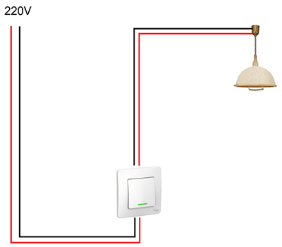
 Now let's look at how to properly connect a light switch from scratch. The connection diagram for a single-key switch is simple. In order for the lamp to light up, two wires are connected to it - phase and zero. In order for the light to be turned off, you need to cut one of the wires and connect a switching device into this gap.
When replacing lamps, you may touch the live part of the socket and receive an electric shock. To avoid this, be sure to install the switch in a phase wire break.
Regardless of the installation method, in practice it looks like this:.
- The main cable is laid, which goes from the power source to the lamp. It is located along the wall at a distance of 150 mm from the ceiling.
- The wire from the switch is routed vertically upward.
- At the intersection of the supply wire and the wire coming from the switch, a junction box is installed in which all the necessary wire connections are made.
Now you can start assembling the circuit. The wiring will be done with a two-core cable. For the convenience of performing this operation, the length of the wires coming out of the box is made such that their ends extend out of it by 20 centimeters; the wires with which the remaining elements of the circuit will be connected are made of the same length. The ends of the wires are stripped of insulation. Connections are made in the following sequence:

Connection of conductors
There are several ways to connect conductors in a box:
- If single-core aluminum or copper wires, then they can be connected by twisting and insulated with PVC tape, while the twisting length must be at least 25 mm.
- If the wires are multi-core (each wire consists of a large number of thin wires), then they are connected using special terminals. If the terminals are closed, then there is no need to insulate them. The choice of terminal type is quite wide, but the main requirement for them is to ensure reliable contact at the connection point. In addition, when choosing, it is necessary to take into account the cross-section of the wires.
- If the wires are copper, they can be connected by soldering, and the soldering area can be insulated.
Please note that copper and copper wires must not be connected together. aluminum wires . Such a compound quickly oxidizes, begins to heat up and becomes a fire hazard. If necessary, use a terminal block where the copper and aluminum will not touch.
Connecting multiple lamps
 You can connect two light bulbs to one switch. To do this, they need to be connected in parallel and connected to the wire going to the lamp. The number of lamps with this connection is limited only rated current the switch itself, but all lamps will turn on and off at the same time. For separate operation it is necessary to use other switching elements.
If, for ease of use, you decide to install a backlit switch, then you must take one point into account. Many modern energy-saving lamps and LED-based lamps with such a scheme will flash periodically, and you will have to either change the lamps or turn off the backlight.
In conclusion, I would like to remind you once again about strict adherence to safety regulations at all stages of the work. Pay special attention to the reliability of the connection of conductors and the insulation of these places.
Light switch connection diagram, as a rule, causes difficulties for many unprepared people, although in principle there is nothing complicated about it. I will try to convince you of this.
This article provides detailed step by step photo instructions in which the complete process of installing and connecting the circuit, as well as connecting its main elements, is explained step by step.
The main misunderstanding is the lack clear example. After all, what do we have in fact, trying to understand the circuit and at least roughly understand the principle of its structure? There is a distribution box under the ceiling, in which there are a bunch of incomprehensible connections, a switch near the door, a chandelier or lamp on the ceiling, and all the wires are hidden under a thick layer of plaster. Figuring out what goes where and how it all works is quite difficult. That is why in this article we approached this issue so seriously, analyzing in detail the entire installation from the very beginning to the end. After reading this manual schemelight switch connections will not cause you any difficulties.
Lighting control
Before we look at the instructions, it should be noted that there are a lot various devices lighting control. Below is a list of the most common:
- single-key light switch (its circuit is discussed in this article);
- two-gang switch Sveta;
- three-key light switch;
- dimer;
- switch with motion (presence) sensor;
- single-key pass-through light switch (switch);
- two-key pass-through light switch (switch).
The choice of lighting control device occurs individually for each specific case, since any of the devices presented in the list above has its own functional features. A more detailed description, purpose and connection of each device can be found in the corresponding instructions presented on our website.
Installation of pre-installation elements of a single-key switch circuit
Any circuit starts with a junction box. This is where everyone will soon gather necessary wires, the cores of which are connected to each other in a certain sequence, creating a single-key switch circuit.

IN in this example the method of execution is given hidden wiring, in a compact form you display what is usually located under the plaster. For hidden and open wiring The switch connection diagram is the same.
We mount the socket box, it is the basis for mounting the socket or switch mechanism.

The installation of this circuit element is presented in more detail on our website at following instructions, And .
Now, let's add a circuit breaker, it performs the function of protecting the electrical circuit from overload currents and short circuit, is installed, as a rule, in the power panel.

To complete the picture, we are missing the last element of the circuit - the lamp; we will install it a little later, but now we move on to next stage.
Laying the wires necessary to complete the single-key switch circuit
It was time to install the wire. In our example, we use a wire of the VVGngP 3*1.5 brand, three-core, with a cross-section of 1.5 mm, intended for permanent electrical wiring inside residential and non-residential premises.
You can read more about this brand of wire in the article, "".
Let's start the installation by laying the wire from the junction box to the socket box.

In the distribution box and socket box you need to leave a supply of wire for connection; 10-15 centimeters will be enough.

Now, we lay the next wire, from the junction box to the lamp.


The next wire will be the final wire of the circuit; it is designed to supply power to the circuit breaker; it goes from the electricity meter or input circuit breaker to the upper contacts of the circuit breaker going to a specific group or direction.

Attention! If you already have a supply wire and there is voltage on it, then before carrying out all electrical work it must be disabled. After disconnecting, you must make sure that there is no voltage on the wire; the easiest way to perform this action is to use a voltage indicator. If necessary, you can use detailed instructions on use given on our website in the article.
We move on to the next stage of the circuit, connecting the equipment.
Connecting protection, control and lighting devices
Let's start by connecting a protection device that will protect the circuit from overloads and short circuit currents. In our example, this role is played by a two-pole circuit breaker.
Also, devices such as voltage limiters and voltage limiters are used as circuit protection devices. To get to know these devices better, find out how they work and what they are intended for, you can follow the appropriate links.
Before starting installation, we need to determine the color of the wires. Our wire comes in blue, black and yellow colors with a green stripe. The blue wire is always used for zero, yellow with a green stripe is ground, white is phase.
Using a knife, carefully remove the first protective insulating layer.

Now let's shoot required amount insulation with phase and neutral conductors for connection, approximately 1 cm.

We insert the stripped wire into the contact terminals and tighten the clamping screws. We check the reliability of the wire by pulling it up from the contact clamp and swinging it left and right. If the wire remains motionless, the contact is good.

Similarly, we connect the outgoing wires to the junction box. Be sure to follow the color scheme of the wires; if on the suitable contacts of the machine the zero is on the top on the right, then on the bottom on the outgoing contacts it should be on the right. Accordingly, the phase will be on the left.
Please note that on the outgoing wires the color of the wire has changed slightly, the phase wire has become completely white. Various manufacturers The wire strands are colored differently, the phase and ground wires are most often subject to changes, the zero is invariably blue. I would recommend For ease of installation, to avoid confusion, use wire from the same manufacturer.
We remove the first outer insulation, measure out the required amount of wire needed to connect to the machine, strip it and connect it. We check the reliability of the wire fastening in the contact clamps; if everything is in order, we move on.

We remove the insulating layer from each core.

We connect the wires to the contacts of the circuit breaker.


In our example, a three-core wire is used and this is not accidental, the fact is that this wire is universal. For example, now you want to hang a lamp in the room that is turned on by a single-key switch, but time will pass and after 3 years of making another renovation, you will want to hang not a lamp, but a chandelier. To connect it, you will need another switch, a two-key one, and it requires not a double, but a triple wire. Having a three-core wire in the junction box, you can easily change the circuit with just one additional twist. Also, if necessary, the third wire can be used as. Such option will do, if you install a lamp with a metal body in a room with high humidity, a grounding contact is usually provided on such lamps.
To connect the grounding wire we use a special contact clamp.

We measure out the required amount of wire, strip it and connect it. We check the reliability of the contact connection.


We do the same on the outgoing contact.


The circuit breaker is connected. All the wires necessary to complete the circuit are in the junction box.

Let's move on to connecting the lamp. In our case, a socket with a light bulb is installed. We prepare the wires for connection, remove the outer insulation, measure out the required amount of wire for connection.

We strip the phase and neutral conductors for connection.

In the case of a light bulb and socket, a grounding wire is not needed; we insulate it and bend it to the side. When connecting a lamp or chandelier, do the same; there is no need to cut it off; it may be useful in the future.
We connect the wires to the socket.


Now our diagram has almost acquired its proper form, to complete the picture we perform.

We strip the wires and remove the required amount of outer insulation.

We don’t need the grounding wire, we isolate it and put it in the socket box. We remove the insulation from the copper core of the phase and neutral wires.

Our single-key switch has plug-in contacts, this will greatly facilitate our connection.

The contact of the suitable phase is indicated by the letter "L", and the arrow extending downwards.

We connect the white wire to the appropriate contact, the blue wire to the outgoing one.

All that remains is to install the mechanism in the socket box (mounting cup) and The switch connection is completed.
Read more about how other electrical wiring elements (sockets, double switches, illuminated light switches, lamps and chandeliers), you can look.
Our scheme has acquired general form, All necessary equipment connected.

Let's move on to connecting the wires in the junction box.
We analyze in detail the connection diagram, how to connect a light bulb and switch

Let's go through the wires again.
The wire on the left is the power supply.

The wire suitable from above goes to the lamp (chandelier). In our example, for a socket with a light bulb.

The bottom wire goes to the switch.

We start wiring the circuit for connecting the switch with the wire going to the switch. We clean it and remove the first layer of insulation. There is no need to cut the wire too much; at least 10 cm of each wire should remain in the box.

We remove the insulation from the copper core of the phase and neutral wires, approximately 4 cm.

Let's move on to the wire that goes to the lamp. We remove the top insulation, strip 4 cm each on the phase and neutral wires.

Now we can start connecting the wires.
Zero comes to the light bulb directly from the supply wire, and the phase is made into a gap. The switch will break it; when you press the power button, it will close the circuit and supply a phase to the light bulb; when you turn it off, it will open and the phase will disappear.
We connect the phase white wire going to the light bulb with the outgoing blue wire of the switch.

Exist different kinds connecting the wires, in our example we make the connection ourselves in a simple way, twist. First, twist the wires together with your fingers.

Then we stretch the connection using pliers and tightly twist both wires together.

We bite off the uneven end of the twist.

In this circuit, we do not use ground wires, so we insulate them and place them in a distribution box so that they do not interfere.


Now let's move on to the power wire. We clean it and prepare the phase and neutral wires for connection.


We insulate the grounding wire and place it in the junction box.

Now, we supply power to the switch. We connect the phase core of the supply wire with the phase core of the wire going to the switch. Twist the two white wires.

And at the end of the circuit, we connect the neutral core of the supply wire to the neutral core of the wire going to the lamp (lamp).

The connection diagram for the single-key switch is ready.
Now, we need to check the operation of the circuit in action. Screw the light bulb into the socket.

Apply voltage. Turn on the circuit breaker.

Using a voltage indicator, we check the correct connection of the circuit, make sure that we have not mixed up anything, there should be a phase on the phase wires, and zero on the zero.

And only after that we turn on the switch.

The light comes on, the circuit is connected correctly. Turn off the voltage, insulate the twists and place them in the distribution box.

The installation of the circuit is completed, the question of how to connect a light bulb and switch is disassembled and explained in detail.

In this work we used:
Material
- distribution box - 1
- socket box - 1
- single-key switch - 1
- lamp - 1
- wire (measured according to the specific measurements of your room)
- circuit breaker - 1
- ground contact - 1
- insulating tape - 1
Tool
- pliers
- wire cutters
- flat screwdriver
- crosshead screwdriver
- voltage indicator
How much we saved by doing the connection diagram ourselves:
- specialist visit - 200 rubles
- installation of an internal distribution box - 550 rubles
- installation ceiling lamp- 450 rubles
- installation of a socket box indoor installation (Brick wall, drilling, installation) - 200 rubles
- installation of a single-key indoor switch - 150 rubles
- installation of a two-pole circuit breaker - 300 rubles
- installation of a grounding contact - 120 rubles
- installation of wires open up to 2 meters (1 meter - 35 rubles), For example, let's take 2 meters- 70 rubles
- installation of wires openly above 2 meters (1 meter - 50 rubles), for example, let's take 8 meters - 400 rubles
- wall gating 8 meters (1 meter - 120 rubles) - 960 rubles
TOTAL: 3400 rubles
*The calculation was made for hidden electrical wiring.


