How to convert a housekeeper converter into a switching power supply?
If you have a housekeeper lamp with a faulty bulb lying around, do not rush to throw it away. Inside the base there is a high-frequency converter circuit, which replaces the large and heavy ballast choke, as in the connection circuits of conventional LDS. Based on this converter it is possible to produce pulse block power supply is 20 watts, and with a more careful approach you can squeeze out more than a hundred.
Below is one of the most common options for housekeeper converter circuits:
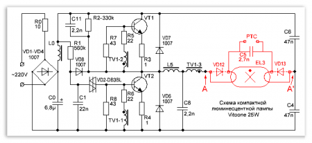
This is the diagram energy saving lamp Vitoone with a power of 25 watts. The red color on it indicates those elements that we do not need, so we exclude them from the diagram, and put a jumper between points A and A’. The only thing left to do is screw a pulse transformer and a rectifier to the output.
A version of the already converted “energy saving” circuit into a switching power supply is shown in the figure below:
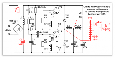
As can be seen from the diagram, R0 was set to 2 times less than the nominal value, but its power was increased, C0 was replaced by 100.0 mF, and TV2 was added at the output with a rectifier for VD14, VD15, C9 and C10. Resistor R0 serves as a fuse and charge current limiter when turned on. Select the nominal capacity C0 so that it is (approximately) numerically equal to the power of the power supply unit you are making.
Regarding capacitor C0: it can be “torn out” from an old Kodak-type film camera, or any other film soap dish; in the flash lamp circuit there is exactly the one we need, 100mF at 350V.
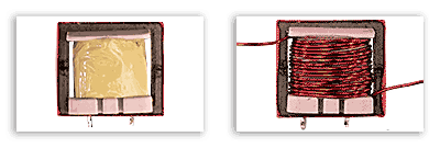
TV2 is a pulse transformer, depending on its overall power, as well as on the maximum permissible current key transistors, depends on the power of the power supply itself. To make a low-power pulsed power supply, it is enough to wind a secondary winding around the existing inductor, as shown in the following diagram:
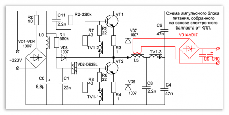
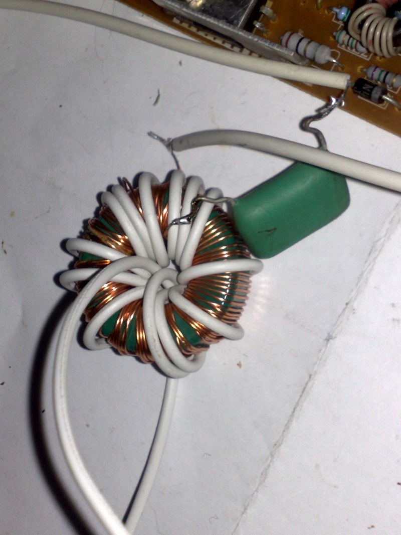
To power any low voltage Charger or a not very powerful amplifier, wind 20 turns on top of the existing winding L5, this will be enough.
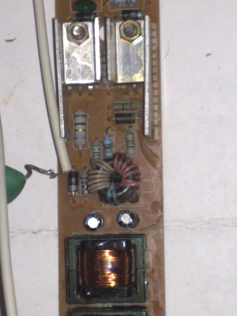
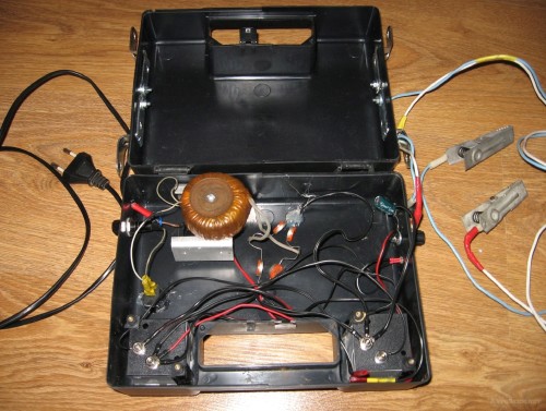
The picture above shows a working version of the power supply without a 20-watt rectifier. On Idling self-oscillation frequency 26 kHz, under load 20W 32 kHz, transformer heats up to 60 ºС, transistors up to 42 ºС.
Important!!! Mains voltage is present on the primary winding when the converter is operating, so be sure to lay a layer of paper insulation that will separate the primary and secondary windings, even if there is already a synthetic protective film on the primary.
But it also happens that in the window of the existing choke there is not enough space for winding the secondary winding, or in the case when we have to create a power supply with much greater power than the power of the “energy saving” being converted - here we cannot do without the use of an additional pulse trance (see second outline of the article).
For example, we make a switching power supply with more than 100W power, and use ballast from a 20-watt light bulb. In this case, you will need to replace VD1 - VD4 with more “current” diodes, and wind the inductor L0 with a thicker wire. If the current gain of VT1 and VT2 is insufficient, increase the base current of the transistors by reducing the ratings of R5 and R6, as well as increasing the power of the resistances in the base and emitter circuits.
If the generation frequency is insufficient, increase the ratings of capacitors C4 and C6.
Practical tests have shown that half-bridge pulse power supplies are not critical to the parameters of the output transformer, because the OS circuit does not pass through it, therefore calculation errors of up to 150 percent are allowed.
Switching power supply 100 Watt.
As already written above, in order to get a powerful power supply, an additional pulse transformer TV2 is wound, R0 is replaced, C0 is replaced by 100 mF, it is advisable to replace transistors 13003 with 13007, they are designed for higher current, and it is better to put them on small radiators through insulating gaskets (mica for example).
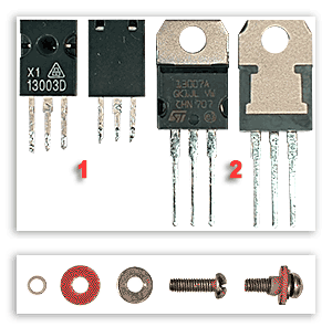
A cross-section of the connection of transistors with radiators is shown in the figure below:

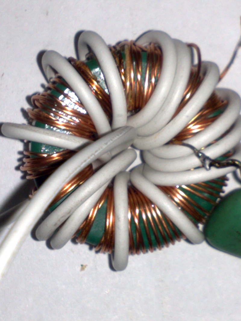
The current model of a switching power supply operating at a load of 100 W is shown in the picture below:
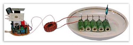
The transformer is wound on a 2000HM ring, outer diameter 28mm, inner diameter 16mm, ring height 9mm.
Due to the insufficient power of the load resistors, they are placed in a saucer of water.
Generation without load 29 kHz, under load 100 W - 90 kHz.
Regarding the rectifier.
To prevent the magnetic circuit of transformer TV2 from entering saturation, make the rectifiers in half-bridge pulse power supplies full-wave, that is, they must be bridged (1), or with a zero point (2). See picture below.
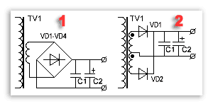
With a bridge circuit, a little less wire is required per winding, but at the same time 2 times more energy is dissipated on VD1-VD4. The second fragment of the figure shows a version of the rectifier circuit with a zero point; it is more economical, but the windings in this case must be absolutely symmetrical, otherwise the magnetic circuit will go into saturation. The second option is used when, with a small output voltage, you need to have a significant current. To minimize losses, silicon diodes are replaced with Schottky diodes, the voltage across them drops less than 2-3 times.
Let's look at an example:
At P=100W, U=5V, TV1 with midpoint, 100 / 5 * 0,4 = 8
, i.e. Schottky diodes dissipate 8 W of power.
At P=100W, U=5V, TV1 with a bridge rectifier and conventional diodes, 100 / 5 * 0,8 * 2 = 32
, i.e. power will be dissipated on VD1-VD4 of about 32 W.
Keep this in mind, and don’t look for half of the missing power later.
Setting up a pulse power supply.
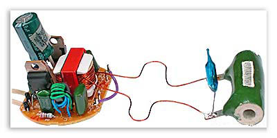
Connect the UPS to the network according to the diagram below (fragment 1). Here HL1 will act as a ballast, which has a nonlinear characteristic and will protect your device if an emergency situation arises. The power of HL1 should be approximately equal to the power of the power supply you are testing.
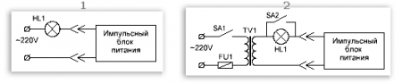
When the power supply is turned on without load, or is operating at a low load, the HL1 filament has little resistance, so it does not have any effect on the operation of the power supply. When some problems occur, the currents VT1 and VT2 increase, the lamp begins to glow, the resistance of the filament increases, thereby reducing the current in the circuit.
If you are constantly repairing and adjusting switching power supplies, it would be a good idea to assemble a special stand (figure above, fragment 2). As you can see, there is an isolation transformer (galvanic isolation between the power supply and the household network), and there is also a toggle switch that allows you to supply voltage to the power supply, bypassing the lamp. This is necessary in order to test the converter when operating under a powerful load.
Powerful glass-ceramic resistors can be used as a load; they are usually green (see figure below). The red numbers in the figure indicate their power.

During long-term tests, when you need to check the thermal conditions of the elements of the power supply circuit, and the load resistors do not have sufficient power, the latter can be lowered into a saucer of water. During operation, the equivalent load gets very hot, so do not grab the resistors with your hands to avoid burns.
If you did everything carefully and correctly, and at the same time used a known-good ballast from an energy-saving lamp, then there is nothing special to adjust. The scheme should work immediately. Connect the load, supply power, and figure out whether your power supply is capable of delivering the required power. Monitor the temperatures of VT1, VT2 (should be no higher than 80-85 ºС) and the output transformer (should be no more than 60-65 ºС).
If the transformer heats up high, increase the cross-section of the wire, or wind the transformer on a magnetic core with a larger overall power, or you may have to do both the first and second.
When heating transistors, place them on a radiator (through insulating gaskets).
If you invented a low-power UPS, and at the same time wound up the existing choke, and it gets hotter during operation permissible norm, try how it works on a lower power load.
You can download programs for calculating pulse transformers in the article:
Happy remodeling.
Sometimes it becomes necessary to have a medium-power switching power supply on hand. Network power supplies using an iron transformer are very large. But besides heavy weight, they have another hidden drawback. If you are planning to assemble a power amplifier with a mains power supply (50Hz transformer), then you must take into account that after the diode bridge the voltage must be filtered.
Smooth out network ripples high frequency it is possible with the help of chokes, and high frequencies do not greatly affect the sound of the amplifier. Low frequency interference is another matter. In modern electronics, it is common to use anti-aliasing filters, which consist of capacitors (both constant and variable). Exactly from total capacity These filters depend on the quality of the output voltage. The main noise is transformed from the network; if the mains voltage rating changes, then the rating at the transformer output will change accordingly. In switching power supplies everything is different. Such power supplies operate at higher frequencies, have a separate generator, control circuit, etc.
This makes it possible to obtain an output voltage whose rating is in no way related to the network one; such a unit will produce a stable output voltage if the input voltage ranges from 90 to 280 Volts.
Electronic ballast (ballast from LDS) was used at 40 watts from a Chinese manufacturer. The transformer is a ferrite ring, the dimensions in my case are 25.4 mm ( Outside diameter) x 15.5mm ( Inner diameter) x 8.5mm (Thickness). The dimensions of the specified transformer are not critical and deviations are permissible (plus/minus 50%).
The primary winding consists of 100 turns of wire with a diameter of 0.3-0.7 mm (0.6 mm in my case). The secondary one is wound based on needs. To obtain 12 volts, the secondary winding contains 7-8 turns. The current in the secondary winding can reach up to 4 Amperes (at a voltage of 12 Volts).
One of the output wires of the ballast is connected to the transformer directly, the other through a capacitor (the capacitance and voltage of the latter are not critical).
The capacitor voltage (C6) can be in the range of 500-5000 Volts (in my case 1600 Volts). It is advisable to select the capacitance; the rating of the current entering the winding depends on it. In my case, the capacitor was used at 6800 pF.

Such a unit can be used for almost any purpose; it is not afraid of a short circuit at the output (as is common with other UPSs), but it is not worth short-circuiting the winding for a long time. It works very stably and silently, is light in weight and compact in size.
Modern power tools are popular because they allow you not to be tied to an electrical outlet during operation, which expands the possibilities of their use, even in field conditions. The presence of a rechargeable battery significantly limits the duration of active work, so screwdrivers and drills require constant access to a power source. Unfortunately, modern instruments(more often made in China) the power supply battery has little reliability and often quickly fails, so craftsmen have to make do with improvised materials in order not only to assemble a switching power supply, but also to save money on it.
An example of such a hand-made product is a switching power supply (UPS) for cordless screwdriver 18 V, assembled from the elements of a non-working energy-saving lamp, which can be useful even after its “death”.
The structure and principle of operation of an energy-saving lamp
The structure of an energy-saving lamp
To understand how an energy-saving lamp can be useful, let’s consider its structure.
The design of the lamp consists of the following components:
Two spirals (electrodes) are connected to the lamp bulb, which, under the influence of current, become heated and emit electrons from their surface. As a result of the interaction of electrons with mercury vapor, a smoldering charge appears in the flask, which “gives birth” to UV radiation. By influencing the phosphor, ultraviolet light “makes” the lamp glow. Colorful temperature"housekeeper" is defined chemical composition phosphor.
Types of breakdowns of energy-saving lamps
An energy-saving lamp can fail in two cases:
- the lamp bulb broke;
- the electronic ballast (EB) (high frequency voltage converter) responsible for the conversion has failed alternating current in constant, gradual heating of the electrodes and preventing flickering of the device during switching on.
If the bulb is destroyed, the lamp can simply be thrown away, and if the electronic ballast breaks, it can be repaired or used for its own purposes, for example, used to make a UPS by adding an isolation transformer and a rectifier to the circuit.
Complete set of electronic ballast for energy-saving lamps
Most EB lamps are high-frequency voltage converters assembled on semiconductor triodes (transistors).
More expensive devices are equipped complex circuit EB, accordingly, is cheaper - simplified.
The electronic ballast is “equipped” with the following electrical elements:
- bipolar transistor operating at voltages up to 700 V and currents up to 4A;
- protective diodes (mainly elements of the D4126L type or similar);
- pulse transformer;
- throttle;
- bidirectional dinistor, similar to dual KN102;
- capacitor 10/50V
- Some electronic circuits are equipped with field-effect transistors.
The figure below shows the composition of the electronic lamp ballast with functional description each element.
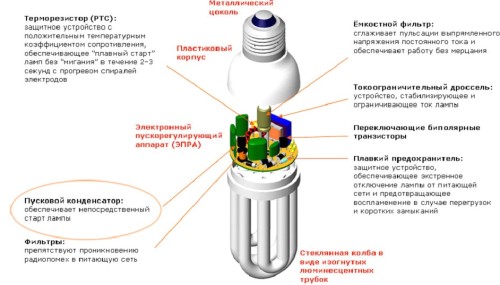
Functional Description
Some EB circuits of energy-saving lamps make it possible to almost completely replace the circuit of a home-made pulse source, adding several elements and making small changes.
Some converter circuits operate on electrolytic capacitors or contain a specialized microcircuit. It is better not to use such electronic circuits, because they are often the source of failures of many electronic devices.
What do the electrical circuits of housekeepers and UPS have in common?
Below is one of the common electrical circuits of the lamp, supplemented jumper A-A’, replacing missing parts and a lamp, a pulse transformer and a rectifier. Schematic elements highlighted in red can be deleted. 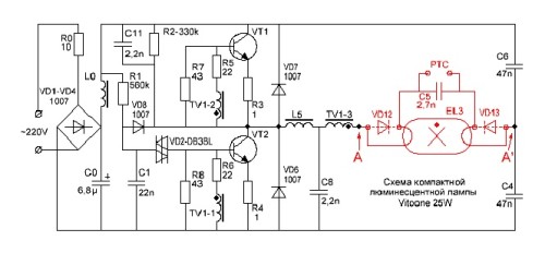
Electrical diagram of a 25 W “housekeeper”
As a result of some changes and necessary additions, as can be seen from the diagram below, it is possible to assemble a switching power supply, where the added elements are highlighted in red.
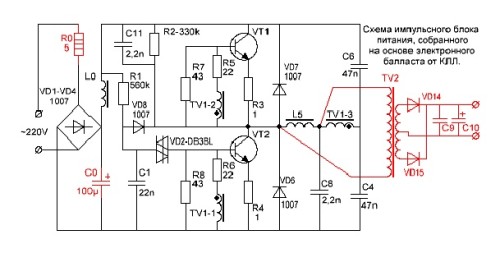
Ultimate electrical diagram UPS
What power supply parameters can be achieved from an energy-saving lamp?
The “second” life of the “housekeeper” is often used by modern radio amateurs. After all, their hand-made products often require a power transformer, the availability of which poses certain difficulties, starting with its purchase and ending with its consumption large quantity wires for winding and overall dimensions final product. Therefore, craftsmen have gotten used to replacing the transformer with a switching power supply. Moreover, if for these purposes you use the electronic ballast of a faulty lighting fixture, this will save a lot of money, especially for a transformer with a power of more than 100 W.
A low-power switching power supply can be built by secondary winding the frame of an existing inductor. To obtain a higher power power supply, an additional transformer will be required. A 100 W switching power supply can be made on the basis of 20-30 W EB lamps, the circuit of which will have to be slightly changed by adding a rectifier diode bridge VD1-VD4 and increasing the cross-section of the inductor winding L0.
Homemade transformer power supply
If it is not possible to increase the gain of the transistors, you will have to increase their base current by changing the values of resistors R5-R6 to smaller ones. In addition, you will have to increase the power parameters of the base and emitter circuit resistors.
At a low generation frequency, you will have to replace capacitors C4, C6 with elements with a higher capacity.
Homemade power supply

power unit
A low-power switching power supply with power parameters of 3.7-20 W does not require the use of a pulse transformer. To do this, it will be enough to increase the number of turns of the magnetic circuit on the existing inductor. The new winding can be wound over the old one. To do this, it is recommended to use MGTF wire with fluoroplastic insulation, which will fill the lumen of the magnetic circuit, which will not require a large amount of material and will provide the necessary power of the device.
To increase the power of the UPS, you will have to use a transformer, which can also be built on the basis of an existing EB choke. Only for this purpose it is recommended to use a varnished winding copper wire, having previously wound it on the original inductor winding protective film to avoid breakdown. Optimal quantity The turns of the secondary winding are usually selected experimentally.
How to connect a new UPS to a screwdriver?
To connect a switching power supply assembled on the basis of an electronic ballast, you need to disassemble the screwdriver by removing all fasteners. Using soldering or heat-shrinkable tubing, we connect the device’s motor wires to the UPS output. Connecting wires by twisting is not a desirable contact, so we forget about it as unreliable. First, we drill a hole in the tool body through which we will run the wires. To prevent accidental tearing out, the wire must be crimped with an aluminum clip at the very hole inner surface power tool housings. The size of the clip, which exceeds the diameter of the hole, will prevent the wire from being mechanically damaged and falling out of the housing.

Screwdriver
As you can see, even after working out, an energy-saving lamp can last a long time, bringing benefits. On its basis, you can assemble a low-power pulsed power supply unit up to 20 W, which will perfectly replace battery 18 V power tool or any other charger. To do this, you can use the elements of the electronic ballast of an energy-saving lamp and the technology described above, which is what craftsmen use, most often to repair a faulty battery or save on the purchase of a new power source.