Signals are information codes that people use to send messages to information system. The signal may be given, but it is not necessary to receive it. Whereas a message can only be considered a signal (or a set of signals) that was received and decoded by the recipient (analogue and digital signal).
One of the first methods of transmitting information without the participation of people or other living beings were signal fires. When danger arose, bonfires were successively lit from one post to another. Next, we will consider the method of transmitting information using electromagnetic signals and dwell on the topic in detail. analog and digital signal.
Any signal can be represented as a function that describes changes in its characteristics. This representation is convenient for studying devices and systems of radio engineering. In addition to the signal in radio engineering, there is also noise, which is its alternative. Noise does not carry useful information and distorts the signal by interacting with it.
The concept itself makes it possible to abstract from specific physical quantities when considering the phenomena associated with the encoding and decoding of information. The mathematical model of the signal in research allows relying on the parameters of the time function.
Signal types
Signals according to the physical medium of the information carrier are divided into electrical, optical, acoustic and electromagnetic.
According to the method of setting the signal can be regular and irregular. A regular signal is represented by a deterministic function of time. An irregular signal in radio engineering is represented by a chaotic function of time and is analyzed using a probabilistic approach.
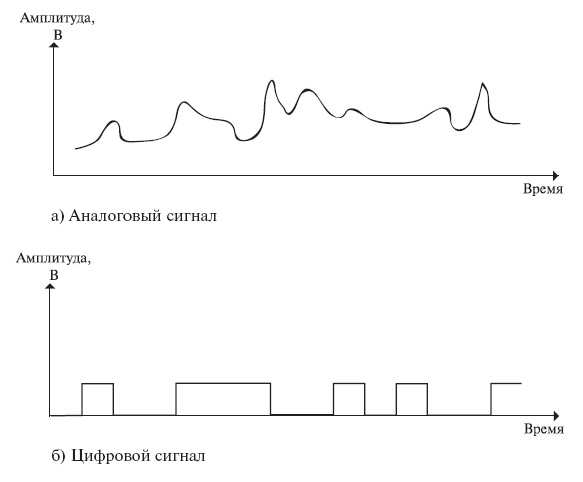
Signals, depending on the function that describes their parameters, can be analog and discrete. A discrete signal that has been quantized is called a digital signal.
Signal processing
The analog and digital signal is processed and directed to transmit and receive the information encoded in the signal. Once the information has been extracted, it can be used in different purposes. In particular cases, information is formatted.
Analog signals are amplified, filtered, modulated and demodulated. Digital, in addition to this, can still be compressed, detected, etc.
analog signal
Our sense organs perceive all the information coming into them in an analog form. For example, if we see a car passing by, we see its movement continuously. If our brain could receive information about its position once every 10 seconds, people would constantly get under the wheels. But we can estimate the distance much faster and this distance at any given time is clearly defined.
Absolutely the same thing happens with other information, we can evaluate the volume at any time, feel how much pressure our fingers put on objects, etc. In other words, almost all information that can arise in nature has an analog form. The easiest way to transmit such information is with analog signals, which are continuous and defined at any given time.
To understand what an analog electrical signal looks like, you can imagine a graph that will display the amplitude over vertical axis and time on the horizontal axis. If we, for example, measure the change in temperature, then a continuous line will appear on the graph, displaying its value at each point in time. To send such a signal with electric current, we need to compare the temperature value with the voltage value. So, for example, 35.342 degrees Celsius can be encoded as a voltage of 3.5342 V.
Analog signals used to be used in all types of communications. To avoid interference, such a signal must be amplified. The higher the level of noise, that is, interference, the stronger the signal must be amplified so that it can be received without distortion. This method of signal processing consumes a lot of energy to generate heat. In this case, the amplified signal itself can cause interference to other communication channels.
Now analog signals are still used in television and radio, to convert the input signal in microphones. But, in general, this type of signal is universally superseded or superseded by digital signals.
digital signal
The digital signal is represented by the sequence digital values. The most commonly used now are binary digital signals, as they are used in binary electronics and are easier to encode.
Unlike the previous signal type, the digital signal has two values "1" and "0". If we recall our example with temperature measurement, then here the signal will be formed differently. If the voltage supplied by the analog signal corresponds to the value of the measured temperature, then a certain number of voltage pulses will be applied in the digital signal for each temperature value. The voltage pulse itself here will be equal to "1", and the absence of voltage - "0". The receiving equipment will decode the pulses and restore the original data.
Having imagined how the digital signal will look on the graph, we will see that the transition from zero to the maximum value is made abruptly. It is this feature that allows the receiving equipment to “see” the signal more clearly. If any interference occurs, it is easier for the receiver to decode the signal than with analog transmission.
However, it is impossible to restore a digital signal with a very high noise level, while it is still possible to “fish out” information from an analog type with high distortion. This is due to the clipping effect. The essence of the effect is that digital signals can be transmitted over certain distances, and then simply cut off. This effect occurs everywhere and is solved by a simple signal regeneration. Where the signal breaks, you need to insert a repeater or reduce the length of the communication line. The repeater does not amplify the signal, but recognizes its original form and produces an exact copy of it and can be used arbitrarily in the circuit. Such methods of signal repetition are actively used in network technologies.
Among other things, digital systems differ from analog systems in the ability to encode and encrypt information. This is one of the reasons for the transition of mobile communications to digital.
Analog and digital signal and digital-to-analog conversion
It is necessary to talk a little more about how analog information is transmitted over digital communication channels. Let's go back to the examples. As already mentioned, sound is an analog signal.
What's going on in mobile phones that transmit information over digital channels?
The sound entering the microphone is subjected to analog-to-digital conversion (ADC). This process consists of 3 steps. Separate signal values are taken at regular intervals, this process is called sampling. According to the Kotelnikov's theorem on the bandwidth of the channels, the frequency of taking these values should be twice as high as the highest frequency of the signal. That is, if our channel has a frequency limit of 4 kHz, then the sampling frequency will be 8 kHz. Further, all selected signal values are rounded or, in other words, quantized. The more levels this creates, the higher the accuracy of the reconstructed signal at the receiver. Then all values are converted into a binary code, which is transmitted to the base station and then reaches the other subscriber, which is the receiver. A digital-to-analog conversion (DAC) process takes place in the receiver's phone. This is an inverse procedure, the purpose of which is to get the output as close as possible to the original signal. Further, the analog signal comes out in the form of sound from the phone's speaker.
3. Signals. Types of signals and their parameters
Characteristics of various signals
All signals can be subdivided into periodical and non-periodic.
A signal is called periodic, the values of which are repeated at certain equal intervals of time, called the signal repetition period, or simply period. For a non-periodic signal, this condition is not satisfied.
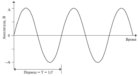
The simplest periodic signal is a harmonic oscillation.
where S, w are the amplitude and angular frequency of oscillation.
Another example of a periodic signal is a sequence of rectangular pulses (Fig. 3.2, a). What do you think this sequence of impulses consists of? It turns out, from sinusoids. Take a look at fig. 3.2. As the initial sinusoid, we choose one in which the oscillation period coincides with the period T rectangular pulses (Fig. 3.2, b)
![]() , (3.1)
, (3.1)
where is the amplitude of the sinusoid, and .
Oscillation (3.2.) of a given frequency and amplitude can be represented as a graph: mark the value on the frequency axis and draw a vertical line with a height equal to the signal amplitude (see Fig. 3.2, b).
The next sinusoid has an oscillation frequency 3 times greater, and an amplitude 3 times smaller.
The sum of these two sinusoids still bears little resemblance to rectangular pulses (Fig. 3.2, v). But if we add sinusoids to them with oscillation frequencies of 5, 7, 9, 11, etc. times large, but with amplitudes of 5, 7, 9, 11, etc. times smaller, then the sum of all these fluctuations:
Rice. 3.2. Periodic sequence of rectangular pulses (a) and the formation of its signal (b–e)
where , will not differ so much from rectangular pulses (Fig. 3.2, G and d). Thus, the degree of "squareness" of the pulses is determined by how many sinusoids with more and more high frequencies vibrations we will summarize.
It may seem that the representation of rectangular pulses as a set of sinusoids is nothing more than a mathematical technique and has nothing to do with reality. However, it is not. Radio engineers are familiar with devices (they are called spectrum analyzers) that allow you to select each sinusoid included in a complex signal.
Direct current is a permanent electrical signal.
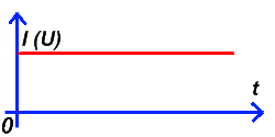
DC current (voltage), or DC signal- an electrical signal that does not change in amplitude and sign for a long time. Direct current sources are ordinary galvanic cells - batteries, accumulators, secondary power sources - adapters for various household appliances, power supplies built into various equipment. I bring the simplest circuit DC supply and its time (emphasis on "o") graph (Fig. 1):
Picture 1
The diagram shows: GB – galvanic battery and R – load resistance (signal lamp).
The concept of a constant signal is used, as a rule, in the elements of automation and digital logic and denotes the presence or absence of voltage at the input or output of any device. State " high level", or "logical unit" (section 3-4) corresponds to the presence of a signal. The state "low level", or "logical zero" (sections 1-2 and 5-6) corresponds to the absence of a signal.
Short-term signals include: impulses various shapes and bursts of pulses.
Pulse is a short signal. The impulse can have a different amplitude I(U) , duration (τ) and form, up to chaotic. All these parameters are determined by the source of this impulse and the elements (electric circuit) through which it passes, changing at the same time. Figure 2 shows the simplest scheme for obtaining rectangular pulse and the time plot of a single rectangular pulse.

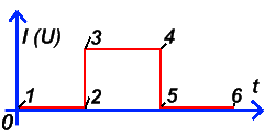
Figure 2
The diagram shows: GB – galvanic battery, S - switch, R – load resistance (signal lamp). The time graph shows the effective current (voltage) at various time intervals:
Plot 1-2 when S off - no current;
Section 2-3 - at the moment of switching on S - the current increases sharply;
Plot 3-4 when S on - the current has a constant value, this section of the graph has the property of a constant current;
Section 4-5 - at the time of shutdown S - the current decreases sharply;
Plot 5-6 when S off - no current.
An impulse whose duration tends to zero is called gamma pulse. Let me explain more simply, the gamma pulse is section 2-3 - at the moment the switch is turned on S in Figure 2. A gamma pulse looks like this:
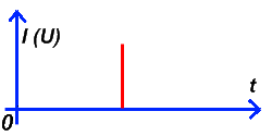
Figure 3: Gamma Pulse
The source of the gamma pulse can be any short circuit electrical circuit resulting in a spark discharge. This can be: natural lightning, a spark that occurs when electrical appliances are turned on and off, a spark from a collector of a running brush motor, or closing (opening) relay contacts.
Of all kinds electrical signals, the gamma pulse is the only one that is present in all frequencies that exist in nature.
In the light spectrum: - in the infrared, in the visible, in the ultraviolet;
In the radio spectrum:- in all ranges of radio waves;
In the audio range:- at high and medium frequencies, and with a decrease in frequency (where this can be neglected), the amplitude of the gamma pulse decreases to zero.
This property of a gamma pulse is called "White noise". In other words, they say: A gamma pulse has a "white noise" frequency spectrum. Pick up a radio and stand close to a working welder. When a spark forms between the electrode and the material being welded, you will see a spark, in addition, you will hear a hum in the receiver that clogs the signal from the radio station, no matter what frequency the receiver is tuned to, but you can barely hear faint sound hissing. The welder wears a mask in order not to burn the retina of the eyes with the powerful ultraviolet light coming from the welding arc.
The gamma pulse is also a source of radiation. Depending on the source of the gamma pulse, the amplitude of its spectrum in different frequency ranges is also different, including the impact on a person. After all, a person is not "irradiated" with radiation from a switch in a room, or a welder from his welding machine.
The gamma pulse is the more pronounced, the greater its amplitude and the lower the load resistance. At the same time, its duration tends to zero as much as possible, and the frequency range expands.
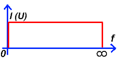
Figure 4: Gamma Pulse Spectrum - "White Noise"
known to all Tesla transformer works thanks to the gamma pulse. If there were no gamma pulse in nature, then there would be no Tesla Transformer itself. My personal opinion about the possibility of existence is also based on the gamma-pulse effect, but this, I set out in another section and article.
Burst of impulses is a series of pulses following each other at set intervals. In a pack, both the impulses themselves (in shape, amplitude, duration) and the time intervals of their repetition can differ. Remote control of various radio devices, as a rule, is carried out by signals, which are bursts of pulses. These are remotes remote control televisions, other household appliances, car alarms, as well as more complex devices.
Types of simple periodic signals
1. Alternating current (voltage)- changing in amplitude and in sign with a certain period T (frequency - ƒ ). Usually, alternating current is called sinusoidal current. All other types, which we will consider below, are also alternating current, but they have other specific names. AC sources sinusoidal current are power generators various types and power in power plants, uninterruptible power supplies for computers that convert D.C. batteries into alternating current. Alternating current, or rather, an alternating voltage of 220 volts with a frequency of ƒ \u003d 50 Hz is available in electrical outlet in every house, unless of course the house is in a cave or deep forest. I give the simplest AC power circuit and its time schedule:

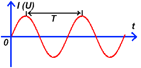
Figure 5
On the diagram: E – alternator. As you can see in the graph, alternating current can be characterized by the following parameters: Current amplitude I - determined by the load, voltage amplitude U and frequency ƒ . For all types of alternating (periodically changing) current, there is a reciprocal of the frequency, it is called the period T . Period is related to frequency by a simple expression:
T = 1 / ƒ
Periodic signals include all of the following types of signals and their varieties. The sources of these types of signals can be special generators or converters.
2. Periodic square wave- this is a signal that has a rectangular shape of its constituent impulses, the amplitude of which is constant (the same). Pulse repetition rate ƒ of a periodic square wave is also constant. Here is a time graph of a periodic rectangular signal:
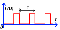
Figure 6: Rectangular Periodic Waveform
In addition to the parameters characterizing a sinusoidal signal, a rectangular signal is characterized by an indicator - pulse duty cycle ( S) is an indicator that characterizes the ratio of the pulse duration to the duration of their absence.
3. Meander- a periodic signal of a rectangular shape, the duration of the pulse and the duration of the pause in the period are equal. In other words, a meander is a periodic rectangular signal with a duty cycle equal to 2. All indicators characterizing a rectangular signal are also suitable for the meander. Here is the meander timeline:
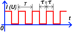
Figure 7: Meander
4. Sawtooth signal- this is a signal that has a sawtooth shape of its constituent impulses, the amplitude and frequency of the impulses, which is constant. Here is a time graph of the sawtooth signal:
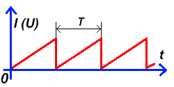
Figure 8: Sawtooth signal
Like a rectangular signal, a sawtooth signal is characterized by indicators - the amplitude of the pulses and the repetition rate (repetition period) of the pulses. The most famous distribution of a sawtooth signal is the sweep generators of televisions and oscilloscopes using a kinescope (electrovacuum tube).
5. Trapezoidal signal is a signal whose pulses have the shape of a trapezoid, the amplitude and pulse repetition rate of which is constant. Here is a time graph of a trapezoidal signal:
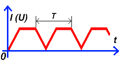
Figure 8: Trapezoidal signal
The trapezoidal signal is characterized by indicators - the amplitude of the pulses, the repetition rate (repetition period) of the pulses. This is the rarest of the periodic signals.
The most important types of electrical signals were listed, all other types are their modifications (combined signals). In addition, all electrical signals can be shifted, both to the region of a more positive voltage, and to the region of a negative voltage, their name does not change from this. You will periodically encounter all of the above signals in amateur radio practice.
There are more complex types signals, such as modulated signals:
Amplitude modulated signal;
Frequency modulated signal;
Phase modulated signal;
Phase-frequency-modulated signal;
Phase-code-keyed signal.
Material carriers of information are signals of various physical nature. In a narrow sense, signals are called fluctuations in electric current, voltage, electromagnetic waves, mechanical oscillations of some elastic medium. Information signals are formed by changing certain parameters of the carrier according to a certain law. Thus, an information signal can be any physical process, the parameters of which can change depending on the transmitted information. This process of changing media parameters is commonly referred to as modulation, and the parameters themselves informational. Unlike a message, receiving a signal after it has been generated is optional.
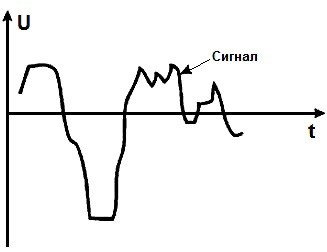
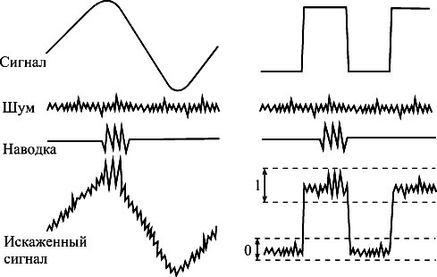
When a signal passes through the physical medium, it is affected by various destabilizing factors, resulting in noise and interference of a very different nature (Fig. 12.4). When registering a signal, the main task is to isolate the useful component from the total signal and to suppress noise and interference as much as possible.
Rice. 12.3.
Rice. 12.4.
To analyze, investigate and process signals it is necessary to use mathematical model signal, which is a mathematical description of the signal. The word "model" comes from the Latin modelium, which means: measure, method, image. The purpose of the model is that it displays only the most important features signal and allows you to abstract from its physical nature and the material form of the carrier. As a rule, the description of the signal is given functional dependence its values from an independent variable, for example, s(t).
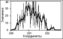
The simplest signals are one-dimensional signals, that is signal value depends on one parameter (for example, sound signals). An example of a one-dimensional signal in figures 12.3, 12.4.
Rice. 12.5.
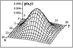
In general, signals are multidimensional functions of spatial, temporal, and other coordinates. An example is the intensity of a computer image p(x, y) (Fig. 12.5).
There are two types of signals according to the form of representation - analog and digital (discrete)(Fig. 12.6). analog signal is defined for any value of the independent parameter, that is, it is a continuous function of a continuous argument. The sources of analog signals, as a rule, are physical processes and phenomena that are continuous in their development (the dynamics of changes in the values of certain properties) in time, in space or in any other independent variable, while the recorded signal is similar (similar) to the process that generates it.
Rice. 12.6.
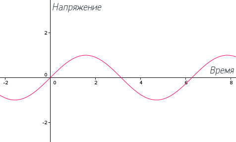
The fundamental analog signal is a sine wave (Fig. 12.7). In general, a sinusoidal signal can be represented as follows:
A sinusoidal signal can be defined by three parameters: maximum amplitude, frequency, and phase. The maximum amplitude is the maximum value or intensity of the signal over time; the maximum amplitude is measured, usually in volts. Frequency is the rate of repetition of signals (in periods per second, or hertz). The equivalent parameter is the signal period T, which is the time during which the signal repeats; hence, . Phase is a measure of relative time shift within a single signal period.
Rice. 12.7.
Most analog signals in nature have more complex shape. Periodic, that is, repeating at a certain time interval, arbitrary waveforms can be represented as a sum harmonic vibrations using the Fourier transform. By applying the Fourier transform, i.e. adding together a sufficient number of sinusoidal signals with appropriate amplitudes, frequencies and phases, you can get an electromagnetic signal of any shape. Similarly, any signal is considered as a set of periodic analog (sinusoidal) signals with different amplitudes, frequencies and phases.
The digital signal can be expressed as follows:

The totality of the spectral components of the signal forms it range. The amplitude of each spectral component characterizes the energy of the corresponding harmonic of the fundamental frequency of the signal. The higher the rate of change of the signal, the more high-frequency harmonics in its spectrum. The difference between the maximum and minimum frequency in the signal spectrum is called signal spectrum width.
In accordance with the change in the amplitude of the analog signal, its power or energy changes, proportional to the square of the amplitude. Depending on the time of signal measurement, there are average and instantaneous power. The decimal logarithm of the ratio of the maximum instantaneous signal power to the minimum is called dynamic range signal.
A sign of a protected signal that allows it to be detected and recognized among other signals is called unmasking. Signs of signals describe the parameters of fields and electrical signals generated by the protected object: power, frequency, signal type, spectrum width, etc.
analog signal is described by a set of parameters that are its features. These include the parameters we discussed earlier:
- frequency and frequency range;
- amplitude (and power) of the signal;
- signal phase;
- signal duration;
- type of modulation;
- signal spectrum width;
- signal dynamic range.
The unmasking signs of signals include the time of their manifestation, depending on which the signals are divided into regular (the time of appearance is known to the recipient) and random (the time of appearance is not known).
The type of information contained in the signal changes its unmasking features. For example, a standard speech signal transmitted over a telephone line has a spectrum width of 300-3400 Hz, audio - 16-20000 Hz, television - 6-8 MHz, etc.
For discrete signals, the amplitude has a finite, predetermined set of values. The most common signal used, in particular, in computers, is a binary signal. The binary signal has two amplitude levels: low and high.
A discrete signal is generally characterized by the following parameters: amplitude, power, pulse duration, period, signal spectrum width, pulse duty cycle (the ratio of the period to the duration of one pulse).
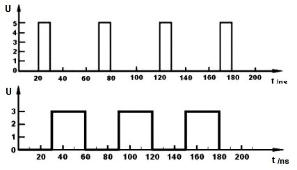
A binary periodic signal is characterized by the following parameters:
When discrete signals pass through wires, their spectrum changes due to various influencing factors from the outside and the properties of the transmission medium. As a result, their shape is distorted and the steepness of the pulses decreases, which reduces the range of their transmission.
The purpose of the story is to show what the essence of the concept of "signal" is, what common signals exist and what their common characteristics are.
What is a signal? This question even Small child will say that it is "such a thing with which you can communicate something." For example, with the help of a mirror and the sun, signals can be transmitted over a line-of-sight distance. On ships, signals were once transmitted using semaphore flags. This was done by specially trained signalmen. Thus, with the help of such flags, information was transmitted. Here's how to convey the word "signal":
In nature, there are a huge variety of signals. Yes, in fact, anything can be a signal: a note left on the table, some kind of sound - can serve as a signal to start a certain action.
Okay, everything is clear with such signals, so I’ll move on to electrical signals, which in nature are no less than any other. But at least they can be somehow conditionally divided into groups: triangular, sinusoidal, rectangular, sawtooth, single pulse, etc. All of these signals are so named for how they look when plotted on a chart.
The signals can be used as a metronome for counting beats (as a clock signal), for timing, as control pulses, for controlling motors, or for testing equipment and transmitting information.
Characteristics el. signals
In a sense, an electrical signal is a graph that shows the change in voltage or current over time. What does it mean in Russian: if you take a pencil and mark the time along the X axis, and voltage or current along the Y, and mark the corresponding voltage values at specific points in time with dots, then the final image will show the waveform:
There are a lot of electrical signals, but they can be divided into two large groups:
- Unidirectional
- Bidirectional
Those. in unidirectional current flows in one direction (or does not flow at all), and in bidirectional current is variable and flows "there" and "here".
All signals, regardless of type, have the following characteristics:
- Period - the time interval after which the signal begins to repeat itself. Most often denoted by T
- Frequency -- denotes how many times the signal will repeat in 1 second. Measured in hertz. For example 1Hz = 1 repetition per second. The frequency is the reciprocal of the period ( ƒ = 1/T )
- Amplitude -- measured in volts or amperes (depending on whether the signal is current or voltage). Amplitude refers to the "strength" of the signal. How much the signal graph deviates from the x-axis.
Signal types
sinusoid
I think that representing a function whose graph in the picture above does not make sense is well known to you sin(x). Its period is 360 o or 2pi radians (2pi radians = 360 o).
And if you divide 1 second by period T, then you will find out how many periods are in 1 second, or, in other words, how often the period repeats. That is, you will determine the frequency of the signal! By the way, it is indicated in hertz. 1 Hz = 1 sec / 1 repeat per second
Frequency and period are inverse to each other. The longer the period, the lower the frequency and vice versa. The relationship between frequency and period is expressed by simple relationships:
Signals that are shaped like rectangles are called "rectangular signals". They can be conditionally divided into just rectangular signals and meanders. A square wave is a square wave whose pulse and pause times are equal. And if we add the duration of the pause and the pulse, we get the period of the meander.
An ordinary rectangular signal differs from a meander in that it has a different pulse and pause duration (no pulse). See the picture below - it says more than a thousand words.
By the way, for rectangular signals, there are two more terms that you should know. They are inverse to each other (like period and frequency). This storytelling and fill factor. The ratio (S) is equal to the ratio of the period to the pulse duration and vice versa for the coefficient. filling.
Thus, the meander is a rectangular signal with a duty cycle equal to 2. Since its period is twice the pulse duration.
![]()
S - duty cycle, D - duty cycle, T - pulse period, - pulse duration.
By the way, the charts above show ideal square wave signals. In life, they look slightly different, since in no device can the signal change absolutely instantly from 0 to some value and back down to zero.
If we go up the mountain, and then immediately go down and record the change in the height of our position on the graph, we will get a triangular signal. A harsh comparison, but a true one. In triangular signals, the voltage (current) first increases, and then immediately begins to decrease. And for a classic triangular signal, the rise time is equal to the fall time (and is equal to half the period).
If such a signal has an increase time less or more than a decrease time, then such signals are already called sawtooth. And about them below.
sawtooth signal
As I wrote above, an asymmetric triangular signal is called a sawtooth. All these names are conditional and are needed simply for convenience.