In this article, we will consider all the intricacies of installation and construction, as well as all the possible problems that may arise if you decide to install sliding gates with your own hands. Usually the biggest difficulty is the drawing of sliding gates. Next, we will consider the basic principles of installing sliding gates with our own hands, video instructions and photos of various designs.
Width
This is the most important question, which, first of all, you must answer. Width refers to the free space between the sliding gate posts when they are completely open. To answer this question, several factors need to be considered:
- What cars will be driving? Cars? KAMAZ trucks? Tractor? Gazelles?
- At what angle will they drive in, especially trucks?
In practice, the width of the gate is made such that when driving, there is a gap of at least 35 cm from all sides between the mirrors of the car and the gate posts.
Practice shows that the optimal width of a sliding gate is approximately 4.5 m, and the ideal width is 5.5 m.
Please note that everything written above refers only to the width of the opening, but not to the width of the canvas. If we consider the canvas, then there is important nuance, which must be taken into account. The width of the canvas must be approximately 25 cm larger than the width of the opening. Otherwise, when the gate is closed, a gap will appear, which can be seen at an angle to the plane.
Height
Some people think that if the height of the canvas adjacent to the fence is 1.8 m, then the height of the canvas must be 1.8 m. In fact, this is not so. let's let's look at an example:
And now let's see what happens in the end. In these cases, you consider the same height of the corrugated board, but do not take into account the fact that in the version with a fence, the profiled sheet will go straight from the ground and its edge from above is clearly 1.8 m above the ground. But, in the case of gates, the bottom edge should not touch the ground, it must be raised by about 15 cm.
It should be noted that the distance between the ground and the bottom of the gate can be adjusted using the adjustment levers, which are usually included in the set of rollers. Roller supports are put on and fixed on the adjusting platforms with nuts, and with the help of them, the installation height of the supports can be adjusted in the range of 6-10 cm.
Further. Unlike a fence, a profiled door leaf, as a rule, is installed in the profile from which the leaf frame is made, and the profile is most often welded from profiled pipe 40x60 mm. The gate height is already obtained: 100 + 40 + 2000 + 40 \u003d 2180 mm. But that's not all, because a guide beam is welded to the canvas below, which has a height of 60mm. That is, taking into account this beam, the distance from the ground to the top will already be 2180 + 60 = 2240 mm. As you can see, according to this scheme, the top edge of the canvas will be 240 mm higher than the top of the fence.
Do-it-yourself drawing and diagram of sliding gates
The design of this type of gate is so simple that you do not need any drawing. Below we explain the scheme of the gate, then you can easily understand their design. So, the basis for the design of sliding gates are two rollers and a moving guide beam along them.
The guide, moving along the rollers, is the basis of the entire structure. It is welded below to the frame and now it moves along the rollers. Since the rollers should not be located in the opening, so as not to get in the way underfoot, they are fixed to the side, outside the opening, and the gate is extended by a "counterweight". A typical design is when the length of the "counterweight" is equal to half the length of the gate opening. In other words, for an opening of 5 m, the length of the frame is 5 + 5/2 = 7.5 m. Moreover, 2.5 m in the frame will be the “counterweight” that goes beyond the opening and is on the rollers.
All other sliding gate components, the drawing of which should be drawn up by a professional, carry almost no loads and are required to protect the door leaf from swinging.
Let's take a look element by element set of accessories, which are required for the installation of sliding gates with your own hands:
- End cap for inner rail. Its purpose is mostly decorative, and also to prevent snow from stuffing inside when the gate rolls back in winter;
- Support rail with 2 adjustment rollers. It is located on top of the post and simply keeps the canvas in a vertical position from tipping over and swinging;
- Upper catcher. It is mounted on a "receiving" pole. The task of the catcher is to protect the web from swaying when they are closed;
- Bottom catcher. Almost the same as in the previous paragraph, but with support platform where the support roller rolls when the gate is fully closed. The task is to keep the gate from swinging, as well as unload the guide and drive rollers;
- Support roller. It is both a plug for the front of the guide and a damper. During the closing of the gate, it enters the “lower catcher”, dampens the impact of the closing ones;
- The guide itself, due to which the gate moves back and forth on the rollers.
- Support rollers with adjustment stands are the elements that ensure the rolling of the gate and carry the main load.
Adjustment stands required for:
- the possibility of replacing roller bearings if they fail;
- adjusting the height of the gate in relation to the ground;
- accurate installation of straight roller bearings.
Do-it-yourself installation of sliding gates
Mortgage
 For most people, the mortgage element raises many questions, since the dimensions and shape of this part are not clear, and everyone is trying to find its design scheme. You don't need a diagram. The task of this element is only to prepare a certain basis on the foundation for further fastening of the rollers and the drive by welding. With this in mind, the shape is absolutely irrelevant, the dimensions may vary. Mortgage channel No. 10-25 is used. The heavier the gate, the more powerful the channel is needed. The mortgage must stand directly on the line of movement of the door leaf, the platform for the electric motor is shifted from this line into the territory.
Foundation
This is probably the most responsible important element the whole structure. To begin with, the foundation is required for a mortgage, where the support rollers will be fixed. Some companies and private builders offer a more economical version of the foundation than reinforced concrete, namely, they offer to twist a pair of screw piles, where the mortgage is then welded up and, by and large, almost everything is ready.
Then, next to it, another one is screwed slightly obliquely into the bunch of piles (since many piles cannot be installed exactly next to each other), under the pole. We will not even consider this method. Probably, it will fit under light and small sliding gates, for example, 2.5 meters long with a light frame, but the longer gates will “walk” on this basis.
We believe that in this case there is no alternative to the reinforced concrete foundation, but it can also be done in different ways. So, for example, it is often proposed to pour only one foundation - directly under the mortgage, or two separate ones, one of them - under the mortgage, the other - under the "receiving" pillar.
This option is much better than the solution of installing screw piles, but the presence of two separate foundations can end in failure, especially if these foundations are not below the ground freezing level. Just as a result of frost heaving, these separate foundations can move independently of each other. In this case, even with small offsets relative to each other, everything can end up with the fact that the gate will not fall into the traps that are on the receiving post, and you will need to reconfigure them all the time.
The solution to this problem is very simple (but more expensive than two separate foundations) - both pillars must unite with one foundation. In this case, even if the base is displaced, both columns will always be parallel to each other, moving in one bundle.
pillars
 They must be installed before pouring the foundation. In the variant with sliding gates, they carry almost no load other than wind. That is, the canvas, the gate, as a rule, has a large "sail" and strong wind, the entire load is transferred from the canvas to the poles. If we consider best option, then for these gates it is enough to use a pipe 65x65x2 mm.
As to whether it makes sense to put U-shaped pillars or ordinary - there is no general opinion. Accessories can be installed without problems on single poles. But the U-shaped option is better, this option is preferable when in the future you plan to install not only the drive, but also a set of automation for the gate, which includes photocells. To begin with, it is much more convenient to install photocells on internal poles, and not on poles outside (taking into account anti-vandal considerations). And also, inside the pillars inside it is quite convenient to lay concealed wiring to signal lamp and photocells.
Frame construction
 The frame is preferably made of metal. Structurally, it is made of pipes of square or rectangular section of several sizes. Cast power frame larger pipes are used, internal filling in the form of stiffeners made from smaller pipes.
It is advisable to immediately weld the gear rack to the frame (or threaded cylinders for the gear rack fasteners). Gear rack fasteners (threaded cylinders, 3 pieces per meter of rack) are standardly included with it. Be sure to check this fact at the time of purchase! In order to install automation later without any problems. Otherwise, then it will be very inconvenient to weld it evenly to the bottom of the canvas.
Its length must be no less than one meter of the length of the opening. This one extra meter (or even more) of the gear rack goes to the "counterweight" in order to constantly be in engagement with the gear wheel of the frame drive motor. The gear rack is universal and fits 99% of drives(NICE, CAME, Alutech, Dorhan and so on). If threaded cylinders are welded for further fastening of the gear rack, it is advisable to weld them first to the guide.
Also, do not forget that if you want to install a wicket in sliding gates (by cutting the wicket directly into the door leaf), then it must be done in that part of the gate that is closest to the support rollers on which the leaf is held. If you want to make a gate at the far end of the leaf from the gate rollers or the middle one, then you can significantly upset the balance of weight distribution, strength, “increase the lever”, that is, those indicators that affect the rollers.
Yes, sliding gates can be quite expensive, but with their manufacturability and simplicity of design, they will give a big head start to lifting and swing gates. Installed clearly in compliance with technology, they are less likely to jam and deform.
Sliding gates are in the same demand as the standard swing. If the installation of such doors on adjoining territory do not think, it is only because they differ relatively complex assembly. However, this is not a reason to refuse gates that, if necessary, go to the side. They can be built by any man who understands the design, made correct calculations and ready to strictly follow the manufacturing instructions.
The design and principle of operation of sliding gates
The basis of the design of sliding gates is a frame that changes its location in space thanks to special trolleys, which are also called cantilever blocks. Equipped with these elements, the gate frame can roll both to the left and to the right.
It is necessary to correctly install the channel to which the sliding gates will be attached
Carts are mounted on a concrete base, created at the beginning of work on the construction of the mechanism of the door structure, mounted away from the driveway. The sliding gate leaf moves along a rail, that is, a narrow steel beam attached welding machine under the frame. The rail acts as a guide and supports the weight of the entire structure.
Principle of operation
Automatic opening and closing of sliding gates is provided by rollers fixed on a swinging base. These structural elements are arranged in pairs, and each of them must be higher than the previously installed one.
In order for the automation to work correctly, the gate needs a counterweight.
In general, the main elements of sliding gates responsible for changing the position of the door leaf are:
- several cantilever blocks that distribute the weight of the structure;
- guide rail;
- end roller, consisting of a platform and a base and guaranteeing a smooth entry of the door leaf into the catcher;
- upper bracket (supporting), excluding deviations and falls of the retractable structure;
- end roller catcher mounted on a holder located near the pole.
With the help of end rollers, the door leaf moves along the rail
Preparation for construction: drawings, sketches, dimensions
Depicting sliding gates on paper, indicating the dimensions, follows after the calculations. To do this, you need to perform the following tasks:
- determine the width of the future gate using the formula L = A + I + (a + b + c + d), where L denotes the width of the structure, A - the width of the passage, I - the distance between the carriages, dimensions a, b, c, d - technological indents ;
- decide what the gate will be in height;
- find out what the counterweight should be, balancing the sash during movement, given that the minimum allowable load length is 40% of the opening width;
- calculate the web weight of the structure, which is affected by the material used (for example, square meter steel sheet 2 mm thick weighs 17 kg);
- Based on the weight of the gate leaf, determine the dimensions of the components and carrier beam, for example, for a structure of 300 kg, a beam with a thickness of about 4 mm with ribs of 9 × 5 cm is needed;
- find out how durable the components should be, that is, take into account the frequency of use of the gate and the strength of the wind.
Before choosing a roller mechanism, you should read some tips. For sliding gates made of profiled sheet, installed in an opening of 4 m, it is best to take reinforced roller bearings up to 350 kg. If you plan to put the gate in an opening of 7 m and sheathe the structure with wood or forged elements, then it is more expedient to purchase sets up to 800 kg.
The roller mechanism must withstand sashes that have considerable weight
Drafting
After doing the calculations, you can start drawing up drawings. In the diagrams, it is required to indicate the main dimensions of the sliding gate, that is, the height and width of the structure, the length of the opening and the guide beam. It is recommended to supplement the drawings with a frame welding scheme.
The drawing must indicate the dimensions of the structure
The choice of building materials and components for the gate
Before proceeding with the manufacture of sliding gates, it is necessary to make right choice material and accessories.
Material selection
It can be difficult to choose the material to create the frame and sash. It is more reasonable to make the backbone of the structure from shaped pipes or wooden bars, and the following building materials should be used for the gate leaf:
- wall corrugated board, which weighs little, is easily mounted, does not deteriorate due to mechanical stress and looks aesthetically pleasing;
- metal sheets that are heavy and therefore require special skills during installation, but guarantee high structural strength;
- wood, the main differences of which are an attractive appearance and quick deterioration in the absence of proper care (mandatory treatment with protective agents is required);
- forged elements that make the gate a real work of art, but require serious investments.
Wall corrugated board is lightweight, so it is easy to install
Deciding to build sliding gates out of wood, forged items or sheet metal, it must be borne in mind that these materials are heavy, which means that you will have to use reinforced fittings and components.
Accessories
For the manufacture of the door structure, you will need the following parts:
- bearing profile;
- supports for rollers and carriages;
- support rollers that will limit vibrations;
- upper and lower catchers;
- a roller that acts as a support;
- guide caps.
When choosing components, you should proceed from the size and weight of the gate
When choosing accessories in a store, one should proceed from the parameters of the opening and the weight of the canvas that will be hung on the frame. In addition to the standard set of accessories, it is recommended to purchase adjusting plates that can eliminate minor errors in calculations without compromising the entire structure.
Material calculation and tool preparation
Usually the opening for the gate is 4 m, and profiled sheets are used in the manufacture of the door leaf, so before starting construction works you need to prepare the following:
- embedded channel 40 cm wide and ½ the width of the gate;
- 15 m of iron bars (reinforcement);
- 10 m 2 wall corrugated board;
- profile pipe 60 × 60 mm in size and at least 5 m long or bricks (for poles);
- pipe 60 × 30 mm, length 20 m;
- pipe 40 × 20 mm, length 20 m;
- liquid concrete M250 with the addition of crushed stone;
- sand;
- coloring emulsion, primer and solvent (one can each);
- packaging of electrodes;
- bracket;
- 200 pieces of rivets and anchors with studs or a set of self-tapping screws (if the posts are metal).
Required Tools
When working with the listed materials, you will need some tools:
- grinder with a disc for cutting metal products;
- apparatus for welding;
- screwdriver;
- drill;
- concrete mixer (for constant mixing of liquid concrete);
- shovel;
- axe;
- a hammer;
- building level, plastic tape with division into centimeters and a plumb line.
Step-by-step instructions for making a gate
Before proceeding with the construction of sliding gates, it is necessary to decide whether to build new pillars or leave the old ones. The second option is possible if the supports are made of brick or reinforced concrete blocks with a section of 20 × 20 mm. You can also refuse to dismantle old poles when shaped metal pipes with a cross section of 60 × 40 mm are securely fixed in the ground. Otherwise, new supporting structures should be erected, for example, brick ones.
Construction of a mechanical structure
The production of sliding gates is carried out in stages:
- First of all, the pillars are erected by completing two brickwork. On each brick support, 3 steel plates 100 × 100 mm in size and 5 mm thick are fixed. The top plate is placed on the inside of the post, mating with the edge next to the opening. At the same time, 20 cm recede from the upper edge of the support. The lower plate is fixed in the same way, and the middle one is fixed in the central zone of the column.
Instead of brick, you can put metal poles
- At the level of zero marks, that is, at the border of the surface at the entrance to the opening, they pull the cord, drawing it close to the back of the pillars and 2 meters further from them. The horizontality of the stretched matter must be checked.
- In the ground, which is adjacent to the supporting pillars, they dig a hole 50 cm wide and at least one and a half meters deep. To reinforce the foundation and ensure its connection with the sliding gate channel, 3 skeletons with a square section (140 cm long) are welded. The fabricated frames are welded from the bottom of the channel, in the middle of its shelf. In this case, the axes of the extreme bones are located at a distance of 40 cm from the edges of the profile, which will be located in concrete base.
- Ten centimeters of the pit are covered with sand and covered with a polyethylene film. The made “pillow” is rammed, after which a channel with reinforcement bones is placed on it. This part is positioned, docking with the carrier column parallel to the gate movement line.
- The structure exposed in the pit is poured with concrete gradually, from time to time making holes in liquid concrete that will allow air bubbles to escape. The top layer of the mixture is smoothed, and the surface of the channel is wiped with a damp cloth. Further work on the foundation is carried out after the concrete has completely hardened, after one or two weeks.
While working with concrete, it must be constantly mixed so that it does not freeze.
- A pipe with a cross section of 60 × 30 mm is divided into segments to create a gate frame. Stiffening ribs and diagonals are attached to it, made of a pipe with a size of 40 × 20 mm. It will be easier to weld parts if you make a mounting table - a structure of three stands of the same height and boards. Before welding, carried out on a special platform, all pipes are cleaned of corrosion using grinder. The seams created by welding are leveled with a grinder, and the protruding ends of the pipes are welded with plugs.
Assembling the gate frame on the mounting table will make the difficult task easier
- A guide beam is welded to the lower zone of the finished gate frame. At first, this part is attached only with clamps to check whether the axles and beams of the structure are in the correct position. After that, welding is used, making seams of 40 mm.
- The skeleton of the gate is placed vertically and coated with a primer that protects the metal from corrosion. After the first layer, a second layer of the agent is applied to the product. The dried composition against corrosion is covered with two layers of paint. The emulsion is not applied only to reverse side carrier beam.
Apply paint evenly with a sprayer
- To metal frame the gate is attached to the sheet of corrugated board. For this use fasteners.
Sliding gate installation
Installing a door structure requires the following steps:

At this stage, you need to check how the gate "walks" and see if the verticality and horizontality of the structure are observed when closed. Gate correction is carried out by adjusting nuts on studs. If no problems are found, then the fasteners need to be tightened.
After inspecting the gate, you can proceed to further installation work:

Video: budget sliding gate option
Usually sliding gates are preferred to be finished with wood materials. At the same time, only construction raw materials are used, the quality of which is beyond doubt. wood flooring the gate must be resistant to mechanical stress, otherwise it will quickly become cracked and lose its shape.
Door structures with wood cladding are a winning option, but they are expensive.
The wood used for cladding the gate must be resistant to mechanical stress.
If it is not possible to invest a lot of money in the construction of sliding gates, then you should think about finishing them with plastisol. True, using this material, the door structure on the territory of a private house will not look respectable. Still, plastisol looks like a smooth or corrugated sheet coated with polyester. But this building material is durable and therefore often used in the construction of parking lots.
Gates made of plastisol are durable and practical
When neither wood nor plastisol is to your liking, you can try to trim the sliding gates with sandwich panels or corrugated board. And the original lining of the door structure will be clapboard lining. Thanks to this material, the gate will become reliable and last a long time.
Having installed sliding gates, you should take care of the safety of their use. The operation of such a door structure requires adherence to the following rules:
- do not create obstacles for the movement of the gate;
- visually control the opening and closing of the structure;
- do not stand in the movement zone of the sash;
- refuse to use the gate if the control devices are damaged;
- do not try to independently alter the design of the gate;
- do not use the gate as a means to move any objects.
Building a sliding gate is not as problematic as it might seem. To put into operation a complex door structure, it is necessary to thoroughly study it and follow all the points of the instructions for manufacturing the object.
Significantly different from the creation of conventional systems for opening passages in walls or fences. This requires optional equipment and the use of special installation techniques. Therefore, the scheme of sliding gates has its own design features, depending on the specific installation site, purpose and principle of implementation of the opening mechanism.
Advantages
The popularity of such systems is directly related to the design. The fact is that it allows you to save space as much as possible. Typical scheme sliding gates involves the displacement of the door along the wall, which means that a large gap is not required in the area of \u200b\u200btheir operation. Given this, in some industries or industrial facilities, the installation of such systems is mandatory. Also, due to the design features and the use of special mechanisms, it is in such gates that it is easiest to implement mechanical opening and its remote control.
An important factor, which is one of the decisive ones when choosing such designs, is that they can be used without leaving the car. You do not need to independently perform the opening and subsequent fixation of the wings, which is very annoying for some drivers. This is very convenient, especially in bad weather conditions.

Flaws
The usual sliding gate layout requires space along the wall or fence, which is necessary to accommodate the leaf. Also, such designs are somewhat difficult to manufacture, which sometimes affects the cost of work. This may require Additional materials to implement the movement mechanism. It is necessary to select the design for a specific installation site. Many standard solutions may just not fit certain areas, although it is worth considering separately all types of such gates to show their main characteristics.
Cantilever gate
Such systems require the presence of a special guide, which is usually mounted at the bottom on the wall and it is she who serves as a support for moving the canvas. Such a recoil scheme is the easiest to make. It's pretty simple design, which is very common. It allows you to use vehicles of any height and has no restrictions. However, in this case, you will have to spend money on the length of the canvas and make a special fixing portal even on the opposite side of the travel mechanism. Also, their disadvantages include high windage, although when creating a small entrance, this is almost imperceptible.

Hanging gate
These structures are usually installed where there is already a height restriction on entry. The fact is that the mechanism for opening them is located on a special rail, on top of the entrance. This is very important to take into account at the design stage, since it is necessary to take into account the possibility of passing vehicles with large dimensions. A typical do-it-yourself scheme for sliding gates is quite simple. It is enough to calculate the principle of fastening the upper guide and already place the suspension mechanism itself on it. Most often, these structures are mounted in spans between workshops or inside large rooms. This allows you to immediately solve the problem with the dimensions of transport and use only the advantages of these systems.
wheel gate
Such structures are most often used to create wide spans. Typically, a diagram and drawing of a sliding gate with dimensions is approximately created. The fact is that the final measurements moving mechanism it is best to produce after mounting the rail, along which the wheels will ride. This design is considered less practical, since even minor obstacles or blockages on the floor can affect the quality of work. However, if you need to create a fairly wide span and there is no way to use suspension system, then this manufacturing option may seem the best.

Drawing
If you take into account all the features of different designs, then you can understand that an individual approach is needed to create sliding gates with your own hands. Design, drawings, diagrams or sketches taken from other objects may not fit a particular span or may not meet the requirements of the end user. Therefore, professionals first recommend approaching this issue based on needs and personal preferences.
First of all, the principle of operation of the structure is determined and, based on these data, a drawing of the canvas is made. Usually, a fairly strong frame is made, and its length is increased by 40%. These are necessary costs that allow you to hide the gap between the sash and the wall and at the same time give the product additional strength.
When a sliding gate design is created, diagrams or drawings are made taking into account the acquisition of ready-made units. These may include rails, rollers, or other prefabricated items. Therefore, before starting work, it is very important to immediately clarify the presence of these nodes and find out all their parameters. The same applies to an automated opening system, which may have its own installation features and therefore needs to be shown in detail on the drawing.

Preparation and grounds
This stage is considered very important, since not only the quality of the structure depends on it, but also the service life that the sliding gates will have. A photo, diagram or drawing will not help in this process, because you need to take into account the individual landscape of the area. At the same time, it is immediately worth noting that support poles with a locking device and a trap are best done on one monolithic base. This will avoid distortions that occur due to uneven subsidence of the soil. Such a kind of foundation is best done to the depth of freezing of the earth, taking into account the soil itself.
- First, they dig trenches under the pillars themselves and connect them together.
- On the next step make a sand substrate, in which you can add a small amount of crushed stone.
- If you plan to install an automatic opening system, then it is better to immediately supply the cable and other control wires.
- Next, reinforcement is made, and the channel is laid up in the connecting trench with the flat side up. It will serve as the basis for a rail or a movable carriage. At this stage, they are performed using a level in order to prevent distortion that will affect the operation of the structure.
- Then the concreting is done. At the same time, it is very important to achieve maximum removal of air during pouring. Therefore, some masters prefer to use special vibrators that are immersed in a solution.
- It is necessary to install the supporting columns of the gate only after the concrete has completely hardened. Usually they are made of brick, immediately wiring and installing seats for fixing metal elements.
Selection of fittings
When creating sliding gates, drawings, diagrams, sketches, the design or instructions of which involve the use of additional fittings, it is very important to choose all the necessary elements correctly. They must match one another and be suitable for the solution. specific tasks. Given this, professionals recommend purchasing ready-made kits. They include all the necessary nodes that allow you to implement a specific type of device with minimal cost. Such elements usually include rollers, trolleys, limit switches, traps and guide rails. These are the main details, which are very expensive to create on your own and do not make sense.
Fabrication of the web frame and carrier frame
Usually used for this purpose profile pipe With rectangular section 60x30. However, when making sliding gates with your own hands, drawings, diagrams or sketches may involve the use of other materials. Docking of all elements is performed using welding. The reinforcing frame can be made from a 40x20 pipe. At the same time, it is very important that it be welded directly along the inner perimeter with stiffeners and spacers.
The supporting frames are made in the same way. However, they do not need a reinforcing frame. It is enough just to install stiffeners and additional spacers. After that, the structure is painted and fixed to the wall.

Installation of the main nodes
At this stage it may be necessary circuit diagram sliding gates and installation instructions for equipment such as rollers, carriages or guides. All nodes are installed in their places, taking into account their design feature and mounting method. Most often, self-tapping screws designed to work with metal or are used. Some experts recommend that you first perform a preliminary installation, followed by fitting all the parts in place. After that, it will be possible to make the final fixation.
When all nodes are installed on the frame, it is possible to mount the frame for the canvas on its load-bearing structure. It also needs to be adjusted using a level. must be installed perfectly, because this is the only way to achieve the correct operation of the product and extend its service life.
Installation of control systems and mechanical opening is carried out in accordance with their installation instructions. In this case, it is also necessary to take into account the specific features of the frame and supporting elements.
sheathing
When a sliding gate scheme is created, drawings and sketches usually involve the use metal profile for sheathing. The fact is that this material has a relatively small weight, good appearance and is very practical. It is fixed using special fastening material in the form of self-tapping screws. Some craftsmen prefer to purchase already painted sheets, for which there are special mounts. Their cost is usually higher, but the appearance of such products is simply amazing. It is also worth noting the fact that factory staining is much better and will last quite a long time. At the same time, it is worth paying attention to products with applied drawings, which will give the designs a peculiar style and uniqueness. However, it should be remembered that the cost of such metal profile sheets is quite high.

- If it is planned that a KAMAZ vehicle will drive into the gate, then their width should be at least 5 meters. Such parameters are taken from calculations of the size of the car, the ability to drive at an angle of 45 degrees and the margin for vibrations or slipping in bad weather.
- Even hanging gate need a concrete base, since the skew caused by the movement of the soil can affect not only the movement system, but also the leaf locking elements.
- All additional elements and automatic opening systems should be purchased from one manufacturer. In this way, problems associated with the incompatibility of individual elements or locking mechanisms can be avoided.
It is necessary to select an automatic gate opening control device very carefully, paying attention not only to the manufacturer, but also to the seller. The fact is that these are questions not only of comfort, but also of safety. That is why many craftsmen prefer to contact special companies that provide such services and give a guarantee for their product, carrying out its periodic maintenance and warranty repairs.
Conclusion
Based on the above material, we can conclude that the sliding gate scheme is created individually. In this case, it is imperative to take into account the type of implementation of the process of moving the web and the presence of control systems. It is also important to pay attention to the manufacture of the structures themselves, since it must not only be durable, but also have a low weight. Therefore, the quality of material selection should be approached very responsibly and without unnecessary savings.
An integral part of the protective structure of the suburban area are the gate. Today there are many varieties of them. Let's look at the process of manufacturing and installing sliding gates with your own hands.
Advantages and disadvantages of this design
Advantages:
- This design of the gate does not interfere with the exit / entry of the vehicle in a small area. Cantilever doors are a great space saver.
- The presence of the lower fastening of the cantilever system allows you to equip the gate under any climatic conditions.
- The finish can be made from different materials, for example, vertical lathing, corrugated board, forging and more.
- The ability to choose a design option, for example, from a sandwich panel or profiled sheet.
- Compared to other types of gates (for example, swing gates), there is no such thing as sagging hinges. The existing automation and the mechanism for closing / opening the gate provides for a long operational period.
- There is a possibility to choose different automation for the gate.
Flaws:
- Unlike other types of gates, for example, swing gates, the arrangement of sliding gates requires more financial costs, by approximately 10–20%.
- To fix the console part and the drive, it is necessary to make an additional foundation.
- Along the fence you will need to allocate sufficient space.

The design of the gate is divided into several types, each of which differs from each other:
- Suspended. Since Soviet times, this heavy, but at the same time robust design gained immense popularity. In it, the canvas on roller trolleys is fixed to a beam, which is located above the driveway, up to 5 m high. As a result, this height is a limitation when high cars enter.
- Console. This type of gate is ideal for the climatic conditions of Russia. This design is not equipped with a beam above the driveway. Such gates will not be able to disable snow drifts, wind, dust and the like. So, the canvas is fixed to the beam using roller trolleys. In this case, the entire structure is fixed on a powerful foundation, which is poured on the side of the opening.
- On the screw piles. To a depth of 1500 mm, metal piles are twisted into the ground, which will be the carriers of the entire structure. Their manufacture and installation will take up to 3 days.
- Mechanical. These gates are opened/closed manually. Mechanical ones are much cheaper in cost and easier to install. They are suitable for those cases where the cottage or country house is rarely used.
- Automatic. Such gates are the exact opposite of mechanical ones. They are equipped with an electric drive and remote control. For regular use, the best option.
Regardless of the type of construction, sliding gates require free space along the fence on one side. Moreover, it should be equal in size to the opening. As for console systems, the space should be 120-200% more.
Gate Calculation Features

Design calculation is one of the most important and priority stages. You should not ignore this stage, since the construction of retractable ones is much more complicated than swing ones.
The calculation process includes the following steps:
- Determining the height and width of the opening. As a result, it will be possible to select the required type of gate for free movement.
- Estimation of the weight of the structure under construction.
- Making a sketch or drawing.
The calculation of the width and height of the structure should be based on the assortment of the market. So, if a profile or pipe can be easily welded, then it is very difficult to cut sheets of corrugated board in order to add it. Plus, the result will be unaesthetic.

Moreover, understanding how much the weight of the structure will ultimately be, appropriate mechanisms and moving parts are selected that can cope with the load.
If the canvas is supposed to be large, then be sure to take into account the wind load. To the available wind strength prevailing in your area, add a small margin.
Although the easiest option for obtaining calculations is to contact a specialized company that will provide a folder with drawings and calculations, you can do it yourself. It should be noted right away that all the above calculations relate to sliding gates of the cantilever type. They are more difficult than all other types, so we will consider them in more detail.

The gate width (L) will be equal to:
- opening width;
- technological indents of opening/closing;
- minimum distance between the centers of the carriages.
Based on this, L will be larger than the opening.

When moving the sash must be balanced. This indicator is achieved by calculating the counterweight. Due to this, the specific gravity of the structure will be evenly distributed over the carriages. Accordingly, in order to have as little load as possible, the counterweight must be large.
But what if there is not enough space for the movement of the sash? In this case, it must be understood that the length of the counterweight should not be less than 40% of the leaf width. The ideal indicator is 50%. As a consequence, the width L has a counterweight in its design.
Having such calculations, you can determine how much space is needed for the gate to roll back along the fence.

This value is determined based on the weight of the material used:
- Decking ~ equal to 4 kg / m 2.
- Steel, 2 mm thick ~ 17 kg/m2.
Gates with a frame of 4 × 2 m will have an average weight of 200 kg. With such data, it is possible to determine the indicators of the guide beam. In this case, you can build on the established standard.
For a gate weighing 300 kg, a 9 × 5 cm beam with a thickness of at least 3.5 mm is sufficient. However, a safety margin of up to 40% is required. It will greatly simplify the operation of the gate and increase its operational life.

The gate will require rollers, catchers and a supporting rail. Modern products of such a plan allow you to choose the necessary design. We take as a basis the simplest estimate of the wind load, which is equal to 12 m/s to 90 kg/m 2 and is evenly distributed over the supporting zones of the web.
How to make sure that the structure you made will work without interruption even in strong winds? To do this, it is necessary to ensure that the strength of the fittings is greater than the calculated weight of the gate. A lateral moment of 100 kg/m is also taken into account, multiplied by 8 kg/m, which equals 800 kg/m. In principle, this is a little ~ for each support element 150–180 kg/m.
Buying roller mechanism, make sure it has a margin of up to 30% in relation to the weight of the gate. But this indicator does not affect the service life. This is directly affected by increasing the distance between the centers of the carriages.

In addition to all of the above, it is worth paying attention to other aspects. Pay attention to the rail for the gate, supports for roller carriages and the number of anchors. It is also important to correctly calculate the mortgages on the supporting pillars. In this case, it is necessary to build on 60% of the total mass of the gate, divided by the number of mortgages.
As for the calculation of the foundation, there are no special secrets here. But despite this, this component should not be overlooked, because often the cost of the foundation reaches 40% of the total cost of the project.

This type of gate has the following structural elements:
- Guide beam. Takes all their weight.
- Trolley or roller support. They need 2 pcs.
- Removable end roller. When closed, it serves as a support.
- Upper/lower catcher. The lower one, when the gate is closed, takes the load, and the upper one reduces the windage.
- Bracket. It is important to keep the sash from lateral swing.
- Stand. A support is installed on it, which organizes the movement of the sash.
Roller supports are installed on the foundation, which take on the load of the guide beam. The rollers are placed inside the carrier console.
Sash selection

High requirements are also placed on the gate leaf. Its design must be sufficiently rigid and stable. This is important so that the sash functions well in case of a strong gust of wind or ice. Moreover, it must be equipped with additional stiffeners so that it does not sag under its own weight. All this should be taken into account when creating drawings.

The presence of certain components directly depends on the height and width of the sash, as well as its weight. So, today on the market you can find a number of companies that provide high-quality equipment, namely:
- Combi Arialdo and Flatelli Comunello from Italy.
- Roltek and Doorhan from Russia.
- Alutech from Belarus.
For example, let's do some calculations. In the basic configuration, a carrier rail with a length of 6 m is necessarily installed. And in order to choose the right accessories for it, it is necessary to take into account the length of the sash and plus 40%. Also, the selection is carried out according to the length of the guide beam and possible loads. So, if the width of the opening is 3.8 m, then the length of the gate is 3.8 m + 40% = 5.32 m. In this case, you can purchase a ready-made set with a beam of 6 m.
If the width of the opening significantly exceeds 4 m, then the purchase of components should be guided by a load of 500 kg. In them, the guide beam has a wall thickness of 3.5 m, and a cross section of 71 × 65 mm. If the width is more than 6 m, then it is necessary to take a load of up to 600 kg from the calculation.
Installation work

The movement of the canvas must be carried out with inside plot, namely along the fence. Based on this, it is necessary to prepare a place for the gate so that absolutely nothing interferes with this process.
The installation process includes 4 steps:
- Electrical wiring.
- Installing a return post.
- Automation installation.

Stages of building a foundation:
- The markup is done first. Measure 500 mm from the fence (width of the foundation). Also measure from the edge of the gate a distance equal to the rollback (the length of the foundation). So, you will see the perimeter of the future foundation.
- It is often possible to use fence posts. If this is not possible, then a return post should be installed on the opposite side. It must be installed so that it is inside the site, and not in the opening itself. Otherwise, it will reduce the width of the opening.
- If the gate will work on automation, then be sure to organize a place for wiring. To do this, you can use a square metal or plastic pipe / box. The diameter of the pipes is not less than 25 mm.
- Now you can start digging a pit. The depth of the trench is up to 2 m, below the freezing level of the soil (it varies in each region).
- For the manufacture of the embedded element, you can use the channel 16. Its length must correspond to the length of the trench. Reinforcement Ø12 mm is laid in the foundation. The reinforcement must be welded to the channel and connected with cross braces.
- Thus, the resulting embedded element is placed with reinforcement down. When laying, make sure that the side of the channel is adjacent to the fence support post. Also, the channel must be set strictly in level and exactly parallel to the opening line of the gate.
The embedded element must be flush with pavement. Minimum Clearance, which is allowed between the lower edge of the gate and the road is 10 cm. This gap can be increased using the adjusting platform. But it will be impossible to reduce this gap without breaking the fasteners.

If for one reason or another a gap of 100 mm is not suitable, then carry out deep installation embedded element.
As for concrete work, they are carried out when the installation of the embedded element is fully completed. The level of concrete must be flush with the embedded element.
Installation

When the foundation has hardened, you can begin to install the gate. To do this, you first need to make markup. Along the line of the opening, not reaching the reciprocal column of 30 mm, pull the cord. This cord is the trajectory of the gate. The cord tension height is 200 mm. Further work is as follows:
- Determine the extreme position of the first and second roller bearings. Step back from the edge of the opening 15 cm along the plane of the embedded element and draw a line for the position of the first trolley. Calculate the line of the second cart as follows: measure the entire length of the gate with the cantilever part and subtract 10 cm from the edge of the counter post along the plane of the embedded element. As a result, you will determine the location of the second cart.
- Now insert the roller bearings into the carrier profile, placing them in the center.
After that, it is necessary to weld the second carriage of the adjustment platform. Then roll out the gate leaf into the opening and make the final position adjustment. Make small tacks by welding the second adjustment pad, as a result, the actions look like this:
- Remove the canvas from the roller cart.
- Next, remove the carts from the platforms.
- Weld pads to the embedded element.
- Attach roller carts to them.
- Slide the canvas onto the roller supports.
- Close the gate and wrench adjust their position.

Inside bearing profile make holes, this is necessary in order to install the trolley correctly. To do this, loosen the top nuts securing the carts to the platforms. After that, roll the gate back and forth. If the sash moves freely, tighten the nuts. If there are some difficulties in moving the sash, then slightly loosen the fasteners and level out all the design flaws, for example, correct the skews of the cart.

- Now you need to install the end roller. It should be inserted into the carrier profile and tighten the bolts well. Also weld the end roller cover to the profile. This will allow the roller to play the role of the end stop in case of manual control of the gate. But in this case, welding fastening will be much better than a bolt.
- As for the end cap of the carrier profile, it is mounted on the inside of the door and welded in place. It is necessary so that the snow does not roll under the rollers.
- Now the upper retainer is mounted to the rollers. Therefore, loosen the fasteners of the rollers and install the brackets so that its side is directed towards the support post, and the rollers grab the top of the blade. With this in mind, press the bracket to the pole and fix it.
At the next stage of work, the sheathing of the gate frame is carried out. To do this, you can use profiled metal sheets. They need to be cut to size. Fastening is carried out with rivets or self-tapping screws. Each subsequent sheet is mounted with an overlap.

When the sheathing is completed, it is possible to install the lower / upper trap. The lower catcher plays the role of reducing the load on the roller carriages when closed. Therefore, they must be installed when the gate is loaded. Bring the lower catcher under the end roller with the door completely closed so that the reference plane of the catcher is higher than the level of the end roller. As for the installation of the upper trap, this process takes place in the same way.

In conclusion, it remains to carry out the installation of automation. To do this, fix the gear rack, which implies a universal part with an electric drive. It is usually included in the fastener kit.

The choice of automation directly depends on the weight of the gate:
- For an opening of 4 m, a drive is used - 500–600 kg.
- For an opening of 4-6 m, a drive is used - 600-1300 kg
- For cases with intensive opening of the gate, a drive is used - 1200–1800 kg.
Coloring

All metal elements of the gate must be painted. Degrease the surface first. To do this, clean the surface and grind it with a grinding disc on a grinder. Some places, for example, protected, wipe with acetone. Now you can start priming. It applies evenly. Moreover, the primer should be applied so that there are no drops or streaks. Thanks to such preparatory work, the paint will lie evenly. As a result, the entire structure of the gate will be completely protected from corrosion.
Paint should be applied in two layers and only after complete drying first.

To carry out all the work, you will need to have such a tool:
- Inverter welding material. Such a unit will not spoil the metal.
- Bulgarian.
- Air compressor for painting.
- Pliers.
- Drill.
- Roulette.
- Level.
- Riveter.

If you do not have sufficient experience in performing such work, then there is a high risk of making some mistakes:
- Not enough good preparation foundation.
- Incorrect installation and fastening of all components.
- Incorrectly selected weight of the gate under the carrier beam.
- If a creak is heard, then this is evidence of sand getting into the bearings.
- Do not allow paint to drip.
- Be sure to consider the depth of soil freezing. Otherwise, the posts may skew in one of the sides.
Video: gate manufacturing
Photo: ready-made sliding gate options


Scheme
On the diagrams you can find a lot of structural details for the manufacture of sliding gates:


In the recent past, not everyone could afford the installation of sliding gates, the fittings were too expensive. And the automation put on them was a completely transcendental dream.
Now the situation has changed, a lot of high-quality and affordable fittings have appeared on the market, and many people prefer to make such gates for themselves because of the simplicity of design and space savings.
Any person familiar with the basics of construction can build them.
Sliding gate types
Sliding gates are a functional, reliable locking mechanism that practically fits into the surrounding space.
The gate moves along the fence, using the minimum area that can be calculated from following formula: the width of the gate, taking into account the movement mechanism, is multiplied by the length of the moving sector.
There are three types of construction:
- . The carrier guide is placed on the bottom leaf, moving, the gate does not come into contact with the ground and moves freely on top. This is the most common design;
- hanging type. Suspended on roller trolleys, the gates are installed with a guide located above the opening. The area for entry / exit is limited at the top. Such structures are put in storage and production hangars, which have a limit set in the upper space;
- Gates on wheels. The carrier rail is installed in the opening and the wheels are mounted to the gate itself. At the same time, it is located in the gate opening, on the foundation.

Cantilever gate
The most successful are sliding gates with a cantilever type design. The space above is free, unlike the design hanging type. It does not require such maintenance (clearing of ice, snow, leaves) as with a structure on wheels.
Pros and cons
The advantages of such gates are:
- the possibility of passage of any transport (the height is not limited by anything);
- the opening process takes place along the fence line on which the gate is installed, which significantly saves area on the site;
- in order to open them, you need to use a minimum of effort, unlike swing ones;
- good burglary resistance (can withstand the ramming of a powerful truck);
- less influence of windage;
- the required automation costs significantly less than swing;
- the prestige of owning such a gate.
- price, which includes expensive branded equipment and a special foundation;
- heaviness and bulkiness of the structure (the length of the gate should be 30-50% more than the length of the opening, and the weight should be two to three times more than swing gates);
- availability of free space along the fence (usually 5-8 meters).
Hardware used for mounting
Thanks to fittings, the gate is stable and driven. The success and reliability of the installation depends on their correct choice. On the construction market you can buy ready-made kits.
When choosing, you need to be guided by the following rules:
- the sash should be 40% wider than the opening;
- the fitting kit is selected taking into account the length of the guide beam, as well as the upcoming load and the intended installation of automation.
So, for openings no more than 4 meters, a set of components is purchased for the required load, not exceeding 500 kg.
This kit includes a guide beam with a section of 71x65 mm, a length of 6 m and a wall thickness of 3.5 mm. And for openings no more than 5 meters, components are purchased that can withstand a maximum load of 600 kg.

You can also purchase the accessory kit separately. It:
- Roller carriages, with the help of which the gate rolls freely on the base.
- guide rail or a guide that is welded to the frame from below and put on the roller carriages with the canvas. This is the base that fastens the carriages and the door leaf, and rolls them on rollers.
- Support rollers. They are mounted from above to the pole of the opening located nearby. Holds the sliding gate structure in a vertical position.
- Roller and catcher. The roller is mounted in the guide, and the trap to the nearest post of the gate opening. When closing the gate, the knurling roller gradually moves into the trap.
- Stubs. This is a protective material that prevents rain, dirt, snow, sand from penetrating the guide rail.
Drawings and diagrams for installation
As a rule, construction begins with drawing up drawings. Below are a few diagrams and drawings of sliding gates that are recommended for do-it-yourself installation. The choice is yours.
Also, by combining everything you need and cutting off the unnecessary, you can create your own drawing for your dacha or home. When choosing a material, you need to be guided by its compatibility with existing buildings.
This is the most simple circuit without electric motor and drive:

In the drawing, automatic metal sliding gates:

The section should be 6 m with an entrance width of 4 m. At the same time, a road clearance of at least 75 mm is required, and the base must be mounted on concrete pillars, i.e., into a foundation dug 1.5 m deep. In order to prevent the gate from sinking under its own weight, the main section is reinforced by fixing with special catchers.
Below is another diagram of a prefabricated structure with a section, supporting pillars and foundation under the base.

Drawing with an electric drive that automates the sectional movement. Scheme of the constructed structure, taking into account the further installation of the automatic drive. The installation will, of course, be an overhead, but it will justify itself by facilitating the opening and closing of the gate, and their control.

Movable metal section equipped with a counterweight and ready for installation. It remains only to sheathe it.

Such a section must be made not heavy, to facilitate its opening / closing. Also lightweight, it will not sag and deform. This will save you from completely unnecessary breakdowns.
And with further installation of an automatic drive for such a section, a less powerful motor will be required, which will save money. Shown below is a sliding gate section made from polycarbonate, known for its excellent lightweight properties.

And the last diagram shows correct parameters and sliding gate ratio. All this is in the upper schemes, but repeated useful information will not hurt.

Self-manufacturing
After all of the above, you can go directly to the installation of the structure.
The first step is to make the foundation and guides. To do this, two or three pillars 1.5 m high are driven into the ground. The value can vary and depends on the parameters of the gate being built.
Pits are dug, which are sprinkled with a drainage layer and reinforced. Then the pillars and the foundation between them are poured with mortar. The main block will stand here, which will fix the movable section (and maybe the section drive).

After that, the gate posts are installed. They can be made of brick, concrete, welded pipes. When installing, it should be taken into account that the distance between them will be used for further mounting the gate.
The drawing below shows all the fasteners that will need to be installed on the pillars and the base for fastening the movable section.
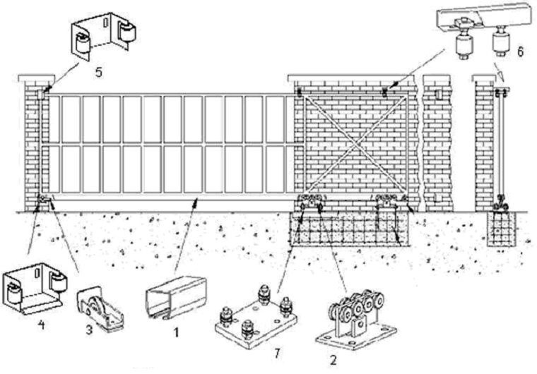
1. guide beam; 2. Roller supports or trolleys; 3. Removable end roller; 4. Bottom catcher; 5. Top catcher; 6. Top latch with rollers; 7. Plate for fixing roller bearings
It is necessary to install a channel on the base foundation, and then on the pillars or wall (depending on the design) the trolley and fixing brackets with rollers. A section of the gate will move along them in the future.

On the other side of the structure, we mount the section catcher and the end roller.
The sequence of work and components may vary depending on the selected scheme!
Sliding gates require a metal section that opens and closes the entrance / exit to the site. It and the frame are cooked exactly in size, it depends right job devices. An example and section diagram is shown above.
The manufactured section must be sheathed suitable materials. They should be light, practical, functional. Sheets of metal, stainless steel, corrugated board, polycarbonate are suitable. The builder's choice.
After that, the structure is sheathed with rivets, bolts, self-tapping screws.
In conclusion, the movable part is mounted on the prepared structure. The fixing brackets remove and fix the section on the channel (guide rail). Then the fixing brackets are placed in their original place. The work, in general, is not difficult, only accuracy and accuracy are required.

After studying the schemes and recommendations for installing sliding gates, you need to decide on your own projects and mounting algorithms for this design that meets the parameters and requirements necessary for a particular site.
You can see how to make sliding gates with your own hands from corrugated board in the video clip:
Another option:
Most builders erecting a sliding gate structure on own site with their own hands, they mount roller carriages on platforms with welded studs.

“It is, of course, convenient and practical. After all, replacement in case of breakdown will be done easily and quickly! ”They think. But this is a mistake.
If the installation is not done correctly, it will be necessary to drill the channel again, make threads, install required size and so on.
A tiny distance will lead to fixing within a few days and will end up cutting the stud and welding the carriage to the base of the foundation.
Therefore, it is necessary to follow the proven instructions, this will allow you to install this design in the shortest possible time, saving effort and money.
Yes, sliding gates will not be cheap, but the simplicity and manufacturability of the device, they will give odds to swing and lifting gates. Installed strictly according to the correct technologies, they are less likely to deform and jam.