Laminar burning rate – the speed with which the flame front moves in the direction perpendicular to the surface of the fresh fuel assembly.
 – laminar combustion zone;
 – speed of laminar combustion.
Turbulent combustion.
Turbulent flame speed – the speed with which the flame front moves in a turbulent flow.
 – turbulent combustion zone;
 – normal speeds of small particles.
Laminar combustion does not provide the required rate of heat release in the engine, so turbulence of the gas flow is required.
Arrhenius equation:
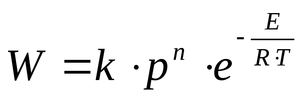 – rate of chemical reaction.
 – chemical reaction constant, depending on the composition of the mixture and the type of fuel;
 – chemical reaction pressure;
 – the order of the chemical reaction;
 –universal gas constant;
 – temperature of the chemical reaction;
 – activation energy is the energy required to break intramolecular bonds.
The influence of various factors on the combustion process in an internal combustion engine with spark ignition.
Composition of the mixture.

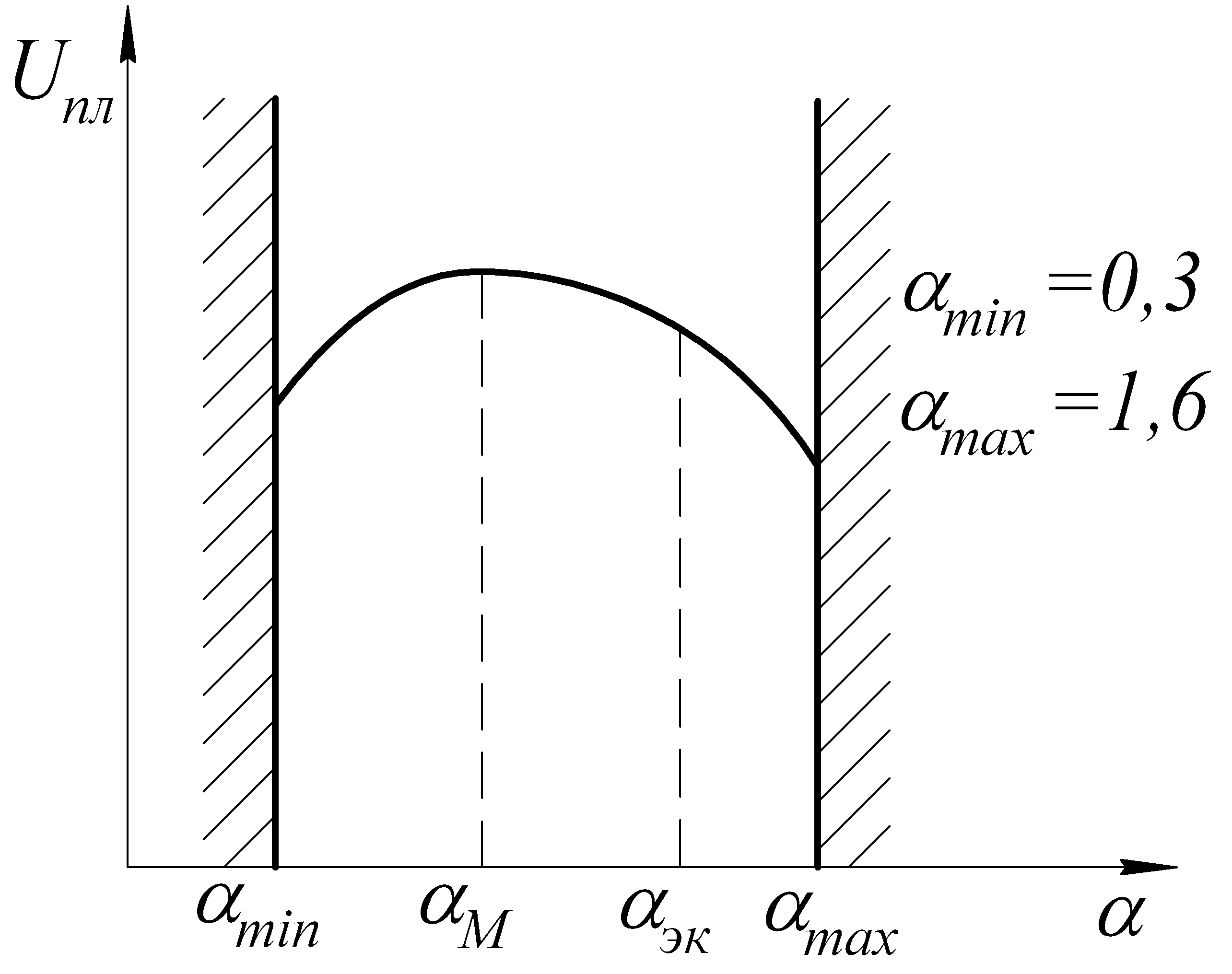 – upper concentration limit;
 –lower concentration limit;
 – normal combustion;

 –power composition of the mixture
– maximum power developed by the engine.
–power composition of the mixture
– maximum power developed by the engine.

 –economic composition of the mixture
– maximum efficiency.
–economic composition of the mixture
– maximum efficiency.
Compression ratio.


With an increase in speed, the ignition phase increases, which leads to a late development of the combustion process and a decrease in the amount of heat released per cycle. Therefore, when changing  regulation of the ignition timing (IPA) is required.
Ignition timing.
Ignition timing – the angle of rotation of the crankshaft from the moment the spark is supplied to TDC.

P 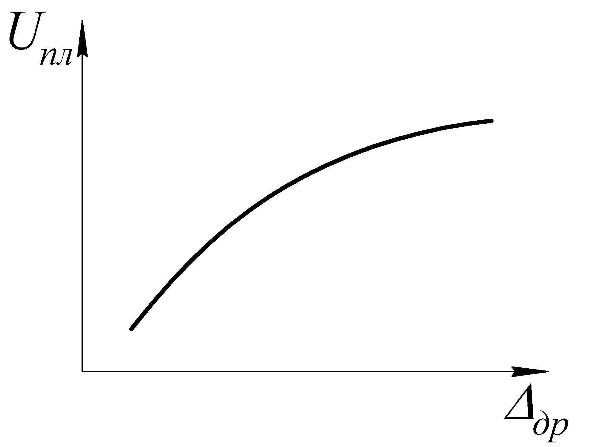 under load
understand the angle of rotation of the throttle valve - this is what regulates the load on the engine.
under load
understand the angle of rotation of the throttle valve - this is what regulates the load on the engine.
 – angle of rotation of the throttle valve.
The main disturbances in the combustion process in spark-ignition combustion engines. Detonation.
D  etonation
– explosive combustion of the mixture, accompanied by shock waves of pressure propagating throughout the volume of the combustion chamber. Detonation occurs as a result of self-ignition of parts of the mixture remote from the spark plug, due to intense heating and compression during the propagation of the flame front.
etonation
– explosive combustion of the mixture, accompanied by shock waves of pressure propagating throughout the volume of the combustion chamber. Detonation occurs as a result of self-ignition of parts of the mixture remote from the spark plug, due to intense heating and compression during the propagation of the flame front.

Upon detonation: 
Reflecting from the walls of the combustion chamber, the shock wave forms secondary flame fronts and sources of self-ignition. Externally, detonation manifests itself in the form of dull knocks when the engine is running under heavy loads.
Consequences of engine operation with detonation:
Overheating and burnout of individual engine components (valves, pistons, head gaskets, spark plug electrodes);
Mechanical destruction of engine parts due to shock loads;
Reduced power and operating efficiency.
That. Prolonged work with detonation is unacceptable.
P  Here are the factors that cause detonation:

The ability of a fuel to self-ignite characterizes detonation resistance , and the detonation resistance is estimated octane number (OC) .
VERY – is numerically equal to the volume fraction of poorly ditonating isooctane in a mixture with easily ditonating normal heptane, which is equivalent in detonation properties to this gasoline.
Isooctane – 100 units, normal heptane – 0 units.
For example: An octane rating of 92 means that this gasoline has the same knock resistance as a reference mixture of 92% isooctane and 8% normal heptane.
A  – motor gasoline;
and – research method for obtaining gasoline;
m – motor method (the letter is usually not written).
In the motor research method, the compression ratio is adjusted until detonation begins, and the octane number is determined from the tables.
Motor methods simulate driving at full load (truck outside the city).
Research method simulates driving at partial load (in the city).


If the octane number is excessively high, then the speed of flame propagation decreases. The combustion process is delayed, which leads to a decrease in efficiency and an increase in exhaust gas temperature. The consequence of this is a drop in power, increased fuel consumption, engine overheating and burnout of individual elements. Maximum engine performance is achieved when the fuel octane number is close to the detonation threshold.
Ways to combat detonation:

Normal flame propagation speed is the speed at which the flame front moves relative to the unburned gas in a direction perpendicular to its surface.
The value of the normal flame propagation speed should be used in calculating the rate of increase in pressure of explosion of gas and steam-air mixtures in closed, leaky equipment and premises, the critical (extinguishing) diameter when developing and creating fire arresters, the area of easily resettable structures, safety membranes and other depressurizing devices; when developing measures to ensure fire and explosion safety of technological processes in accordance with the requirements of GOST 12.1.004 and GOST 12.1.010.
The essence of the method for determining the normal speed of flame propagation is to prepare a combustible mixture of known composition inside a reaction vessel, ignite the mixture in the center with a point source, record changes in pressure in the vessel over time and process the experimental pressure-time relationship using a mathematical model of the gas combustion process in closed vessel and optimization procedures. The mathematical model makes it possible to obtain a calculated pressure-time relationship, the optimization of which using a similar experimental relationship results in a change in the normal speed during the development of an explosion for a specific test.
The normal burning rate is the speed of propagation of the flame front relative to the unburned reagents. The burning rate depends on the row physical and chemical properties reagents, in particular thermal conductivity and the rate of chemical reaction, and has a very specific value for each fuel (with constant conditions combustion). In table Table 1 shows the combustion rates (and flammability limits) of some gaseous mixtures. Fuel concentrations in mixtures were determined at 25°C and normal atmospheric pressure. With noted exceptions, flammable limits are obtained using flame propagation in a pipe with a diameter of 0.05 m, closed on both sides. Fuel excess coefficients are defined as the ratio of the volumetric fuel content in a real mixture to the stoichiometric mixture (j1) and to the mixture at the maximum combustion rate (j2).
Table 1
Burning rates of condensed mixtures (inorganic oxidizer + magnesium)
| Sheet |
| Document no. |
| Signature |
| date |
| Sheet |
| TGiV 20.05.01.070000.000 PZ |
As can be seen, when burning air gas mixtures at atmospheric pressure u max lies in the range of 0.40-0.55 m/s, and - in the range of 0.3-0.6 kg/(m2-s). Only for some low molecular weight unsaturated compounds and hydrogen u max lies in the range of 0.8-3.0 m/s, and reaches 1–2 kg/(m2s). By increase And max of the studied combustibles in mixtures with air can be
Arrange in the following row: gasoline and liquid rocket fuels - paraffins and aromatics - carbon monoxide - cyclohexane and cyclopropane - ethylene - propylene oxide - ethylene oxide - acetylene - hydrogen.
| Change |
| Sheet |
| Document no. |
| Signature |
| date |
| Sheet |
| TGiV 20.05.01.070000.000 PZ |
The linear combustion rate of oxygen mixtures is significantly higher than that of air mixtures (for hydrogen and carbon monoxide - 2-3 times, and for methane - more than an order of magnitude). The mass combustion rate of the studied oxygen mixtures (except for the CO + O2 mixture) lies in the range of 3.7-11.6 kg/(m2 s).
In table Table 1 shows (according to N. A. Silin and D. I. Postovsky) the combustion rates of compacted mixtures of nitrates and perchlorates with magnesium. To prepare the mixtures, powdered components with particle sizes of nitrates 150-250 microns, perchlorates 200-250 microns and magnesium 75-105 microns were used. The mixture was filled into cardboard shells with a diameter of 24-46 mm to a compaction coefficient of 0.86. The samples were burned in air at normal pressure and initial temperature.
From a comparison of the data in Table. 1 and 1.25 it follows that condensed mixtures are superior to gas mixtures in mass and inferior to them in linear combustion rate. The burning rate of mixtures with perchlorates is less than the burning rate of mixtures with nitrates, and mixtures with alkali metal nitrates burn at a higher rate than mixtures with alkaline earth metal nitrates.
table 2
Limits of ignition and burning rate of mixtures with air (I) and oxygen (II) at normal pressure and room temperature
| Sheet |
| Document no. |
| Signature |
| date |
| Sheet |
| TGiV 20.05.01.070000.000 PZ |
| Change |
Methods for calculating the burnout rate of liquids
| Change |
| Sheet |
| Document no. |
| Signature |
| date |
| Sheet |
| TGiV 20.05.01.070000.000 PZ |
![]() ; (16)
; (16)
Where M- dimensionless burnout rate;
 ; (17)
M F- molecular weight of the liquid, kg mol -1;
d- characteristic size of the burning liquid mirror, m. Determined as the square root of the combustion surface area; if the combustion area has the shape of a circle, then the characteristic size is equal to its diameter. When calculating the rate of turbulent combustion, one can take d= 10 m;
T k- boiling point of the liquid, K.
The calculation procedure is as follows.
The combustion mode is determined by the value of the Galileo criterion Ga, calculated by the formula
Where g- free fall acceleration, m s -2.
Depending on the combustion mode, the dimensionless burnout rate is calculated M. For laminar combustion mode:
For transient combustion mode:
if , then ![]() , (20)
, (20)
if , then , (21)
For turbulent combustion mode:
; ![]() , (22)
, (22)
M0- molecular mass of oxygen, kg mol -1;
n 0- stoichiometric coefficient of oxygen in the combustion reaction;
n F- stoichiometric coefficient of liquid in the combustion reaction.
B- dimensionless parameter characterizing the intensity of mass transfer, calculated by the formula
![]() , (23)
, (23)
Where Q- lower heat of combustion of the liquid, kJ kg -1;
| Change |
| Sheet |
| Document no. |
| Signature |
| date |
| Sheet |
| TGiV 20.05.01.070000.000 PZ |
c- isobaric heat capacity of combustion products (assumed to be equal to the heat capacity of air c = 1), kJ kg -1 K -1 ;
T0- ambient temperature, assumed to be 293 K;
H- heat of vaporization of liquid at boiling point, kJ kg -1;
c e- average isobaric heat capacity of a liquid in the range from T0 before T to.
If the kinematic viscosity of the vapor or the molecular weight and boiling point of the liquid under study are known, then the rate of turbulent combustion is calculated using experimental data according to the formula
Where m i- experimental value of the burnout rate in the transitional combustion mode, kg m --2 s -1 ;
d i- diameter of the burner in which the value was obtained m i, m. It is recommended to use a burner with a diameter of 30 mm. If laminar combustion is observed in a burner with a diameter of 30 mm, a larger diameter burner should be used.
3. SPREAD OF FLAME IN GAS MIXTURES
The speed of flame propagation during the combustion of solid, liquid and gaseous substances is of practical interest in terms of preventing fires and explosions. Let us consider the speed of flame propagation in mixtures of flammable gases and vapors with air. Knowing this speed, it is possible to determine safe gas-air flow rates in a pipeline, shaft, ventilation unit and other explosive systems.
3.1. FLAME SPREAD RATE
As an example in Fig. Figure 3.1 shows a diagram of exhaust ventilation in a coal mine. From the drifts of mine 1, via pipeline 2, a dusty mixture of air and coal dust is removed, and in some cases, methane released in the coal seams. If a fire occurs, the flame front 3 will spread towards the drifts 1. If the speed of movement of the combustible mixturew will be less than the speed of propagation of the flame frontAnd relative to the walls of the tube, the flame will spread into the shaft and lead to an explosion. Therefore, for normal operation of the ventilation system, it is necessary to comply with the conditions
w > u.
The speed of removal of the explosive mixture must be greater than the speed of propagation of the flame front. This will prevent flames from entering the mine shafts.
Rice. 3.1. Scheme of flame propagation in the mine:
1 – shaft; 2 – pipeline; 3 – flame front
The theory of flame propagation, developed in the works of Ya.B. Zeldovich and D.A. Frank-Kamenetsky, is based on the equations of thermal conductivity, diffusion and chemical kinetics. Ignition of a combustible mixture always begins at one point and spreads throughout the entire volume occupied by the combustible mixture. Let's consider a one-dimensional case - a tube filled with a combustible mixture (Fig. 3.2).
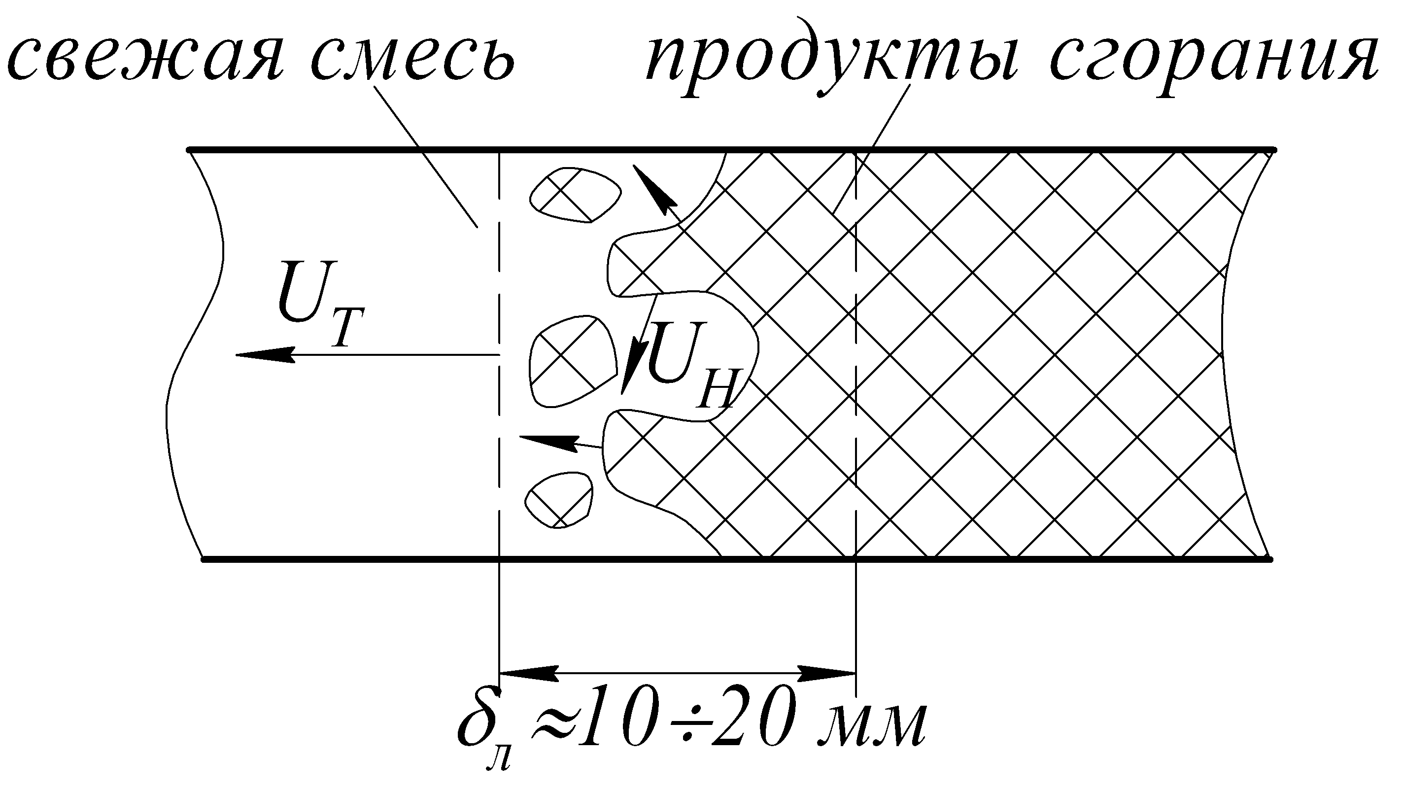
If the mixture is ignited at one end of the tube, then a narrow flame front will spread along the tube, separating the combustion products (behind the flame front) from the fresh combustible mixture. The flame front has the form of a cap or cone, with its convex part facing the direction of the flame movement. The flame front is a thin gas layer (10 -4 ÷10 -6) m wide. In this layer, which is called the combustion zone, chemical combustion reactions take place. The temperature of the flame front, depending on the composition of the mixture, is T= (1500÷3000) K. The released heat of combustion is spent on heating the combustion products of the fresh combustible mixture and the walls of the tube due to the processes of thermal conductivity and radiation.

Rice. 3.2. Scheme of flame front propagation in a tube
When the flame front moves in the tube, compression waves arise in the combustible mixture, which create vortex movements. Swirls of gases bend the flame front without changing its thickness and the nature of the processes occurring in it. On a unit surface of the flame front, the same amount of substance always burns per unit time ![]() . The value is constant for each combustible mixture and is called the mass burning rate .
Knowing the flame front areaS, you can calculate the mass of a substance M, burned in the entire combustion front per unit time:
. The value is constant for each combustible mixture and is called the mass burning rate .
Knowing the flame front areaS, you can calculate the mass of a substance M, burned in the entire combustion front per unit time:
Each element of the flame front dSalways moves relative to the fresh mixture in the direction of the normal to the flame front at a given point (Fig. 3.2), and the speed of this movement:
where is the density of the fresh combustible mixture.
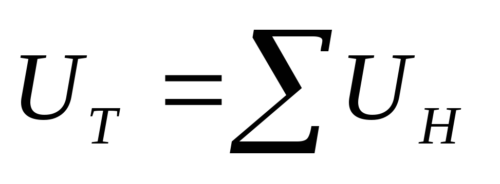
Magnitude is called the normal flame propagation speed and has the dimension m/s. It is a constant value of the combustion process of a given mixture and does not depend on the hydrodynamic conditions accompanying the combustion process. The normal speed of flame propagation is always less than the observed speed And, that is, the speed of movement of the combustion front relative to the walls of the tube:
u n< u .
If the flame front is flat and directed perpendicular to the axis of the tube, then in this case the observed and normal flame propagation speed will be the same
u n = u .
Area of convex flame frontS issueAlways more area flat frontS pl, That's why
> 1.
Normal flame propagation speedu nfor each combustible mixture depends on the admixture of inert gases, the temperature of the mixture, humidity and other factors. In particular, preheating the combustible gas increases the speed of flame propagation. It can be shown that the speed of flame propagationu nproportional to the square of the absolute temperature of the mixture:
u n .= const · T 2.
In Fig. Figure 3.3 shows the dependence of the speed of flame propagation in the combustible mixture “air – carbon monoxide” depending on the concentration of CO. As follows from the graphs above, the speed of flame propagation increases with increasing temperature of the mixture. For each temperature value, the flame propagation speed has a maximum in the region of carbon monoxide CO concentration equal to ~ 40%.
The speed of flame propagation is affected by heat capacity inert gas. The greater the heat capacity of an inert gas, the more it reduces the combustion temperature and the more it reduces the speed of flame propagation. So, if a mixture of methane and air is diluted with carbon dioxide, then the speed of flame propagation can decrease by 2–3 times. The rate of flame propagation in mixtures of carbon monoxide with air is greatly influenced by the moisture contained in the mixture, the presence of soot particles and admixtures of inert gases.

Rice. 3.3. Dependence of flame propagation speed
on the concentration of carbon monoxide in the mixture
Lubricants
The main goal in developing environmentally friendly lubricants is to create a product with high biodegradability and low ecotoxicity. IN developed countries West in
Currently, public and private companies are beginning to create a market for environmentally friendly lubricants. Most studies focus on the chemical composition of the product and assessing its biodegradability. When creating environmentally friendly lubricants, two main directions are considered: the production of base oils, the chemical nature of which determines the nature of the impact on environment, and the synthesis of new additives - environmentally friendly, biodegradable and effective.
Currently, and likely in the future, three groups of base oils obtained from various raw material sources are of particular importance: hydrocracking petroleum oils (HC), polyalphaolefins (PAO) and esters, which are susceptible to rapid biodegradation in the environment. Base petroleum oils of traditional flow schemes will undoubtedly remain of great importance for an indefinitely long period, especially taking into account the fact that lubricants obtained on the basis of PJSC. polyalcohol esters, polyalkylene glycols and diesters have a cost 2-10 times more than petroleum products. Increased biodegradability is not an incentive to overcome price differences.
High performance characteristics and environmental friendliness of mineral oils are ensured by a set of certain qualities. First of all, this is their narrow fractional and favorable group chemical composition with a minimum amount of sulfur and nitrogen-containing compounds in base oils. The selection of raw materials, sorting of oils used in the production of high-index oils, and their separate processing are of paramount importance. In obtaining base mineral oils that meet environmental requirements, selective purification plays an important role,
significant carcinogenicity of the product. Currently, in the USA and Canada, over 70% of base oils are obtained through selective refining. The use of modern processes such as hydrocracking, hydrodewaxing, and hydroisomerization opens up wide possibilities. These technologies are described in detail in the work. The use of hydrocatalytic processes in combination with traditional methods of purifying oil raw materials with selective solvents improves the performance and environmental properties of base oils.
In table 1.4 provides comparative data on chemical composition base oils obtained using selective refining and hydrotreating. The latter significantly reduces the content of arenes, sulfur and nitrogen in oils.
Table 14
Effect of Hydrotreating on Chemical Composition
base oils
The introduction of hydrocracking and hydroisomerization processes into the production of base mineral oils makes it possible to obtain products that are highly biodegradable and do not contain arenes. Hydrocracked oils, according to results obtained using modern methods tests, non-toxic, the practical absence of arenes in them indicates a very low carcinogenicity and an insignificant probability of its growth through the formation and accumulation of polycyclic arenes during operation; absence of arenas and predominant
The use of isoparaffins ensures fairly high biodegradability.
In the USA, hydrocracking base oils have been produced since the end of 1996. . The installation in Finland is ready for start-up.
In Russia, VNIINP, together with the scientific and engineering center of OJSC LUKOIL and JSC LUKOIL - Volgogradneftepe-rerabotka, are conducting research on organizing the production of a number of scarce oils and bases using hydrogenation technologies, in particular, aviation oil MS-8 and aviation hydraulic fluid AMG -10.
Compared to mineral oils, synthetic oils in some cases have better environmental characteristics. The most important classes of synthetic oils from the point of view of environmental safety include oils made on the basis of synthetic esters, polyalphaolefins and polybutenes. They are non-toxic, non-carcinogenic, and characterized by low emissions of harmful substances.
Synthetic oils based on esters with additives have been widely used in gas turbine engines of civil and military aircraft since the 60s. At CIAM, together with VNIINP and the 25th State Research Institute of the Ministry of Defense of the Russian Federation, work is being carried out to create a high-temperature-high (up to 240 ° C) ester oil using effective additive compositions that are not inferior in quality to the best foreign oils. Analysis of scientific, technical and patent information on oils for aviation gas turbine engines shows that polyol esters remain the main class of compounds for use as base stocks [PO]. However, the situation is changing with the next generation of aircraft engines, as improvements in design and the need to reduce fuel consumption lead to increases in pressure, temperature and oil load.
The latter contributes to the risk of local carbon deposits. Therefore, for military aviation in the future, it is necessary to eliminate the use of ester-based oils. For this purpose, the most promising oils are a new type - based on perfluoroalkyl polyethers. According to modern data, these compounds are non-toxic and are even used abroad in perfumery and for the conservation of marble monuments of art and architecture.
Additives have a great influence on the environmental properties of lubricants. In aviation oils, such traditional antioxidants and corrosion inhibitors as dioctyldiphenylamine, phenyl-α-naphthylamine, benzotriazole, K-51 succinimide type additive and others that have proven themselves are widely used as additives.
All over the world, work has been underway for a long time to create new non-toxic and biodegradable products. In particular, since the 90s, the development of substitutes for chlorine-containing additives has been carried out. The issue of replacing lead compounds is important. Bismuth compounds are a substitute for lead. The development of a bismuth dithiocarbamate additive has begun.
Such additives have been developed as Mif-1 (an additive of a complex composition of the benzene type), Irganox L-57 (an antioxidant additive from Shiba, octylated and butylated diphenylamine), additive “X” (a fluorine-containing compound with functional groups of oxysulfite and hydroxycarbamate), etc.
The properties of known additives are improved. Thus, in tricresyl phosphate the content of the neutrotoxic ortho isomer is reduced to 3% (Russia), and in the USA tricresyl phosphate is produced that does not contain the ortho isomer.
Fire and explosion hazard of avnafuels and lubricants
Currently used aviation fuels and lubricants are fire hazardous products. In terms of fire, gas fuels are especially dangerous. Hydrocarbon fuels (jet fuels, gasoline, etc.) are classified as flammable liquids (flammable liquids). They are characterized by high heat production (-2000 ° C) and evaporation, they easily create flammable mixtures with air, which, when burned, form a large number of combustion products (large stoichiometric coefficient), which are good dielectrics and, therefore, can accumulate charges of static electricity.
Based on fire hazard, flammable liquids are divided into three categories. Flash point is used as a determining indicator (it is determined according to GOST 12.1.044-89):
Depending on the auto-ignition temperature (determined according to GOST 12.1.044-89), hydrocarbon fuels belong to one or another group of explosive mixtures of vapors with air:
We dare vapors of hydrocarbon fuels with air belong to the TTA explosion hazard category: it is determined according to GOST 12.1.011-78. This indicator is used when choosing the type of explosion-proof electrical equipment and when designing fire extinguishers.
The fire hazardous properties of the fuel are also determined by the concentration ignition limits (CFL) - the minimum and maximum content of fuel vapor in a mixture with air (oxidizer), at which a flame can spread through the mixture to any distance from the ignition source (GOST 12.1.044-89). Important characteristic fuel are the temperature limits of ignition - temperatures at which saturated fuel vapors in the air are in concentrations equal to the lower or upper CPV, respectively. Important has the minimum electrical discharge energy required to ignite the vapor-air mixture.
When assessing the fire hazard when handling fuels, the burnout rate is also determined - the amount of fuel burned per unit time from a unit surface; minimum ignition energy - to ensure electrostatic intrinsic safety. The interaction of burning fuel with water-foam extinguishing agents is assessed (according to GOST 12.1.044-89).
A fire is often preceded by an explosion of a gas-air mixture. In the event of an explosion of air mixtures in pipes large diameter and length, detonation combustion may occur, propagating at a speed of 1100-1400 m/s. The pressure can increase to 0.8 MPa or more. A fast-acting shock wave causes a sharp increase in pressure, temperature and density of the combustible mixture, which, in turn, accelerates the chemical combustion reactions and enhances the destructive effect.
Explosive concentrations of fuel vapors with air can form over a wide range of temperatures and especially in enclosed spaces and containers. The nature and content of precautionary measures are regulated by special departmental instructions. The essence of the precautions is to prevent the occurrence of a heating source, especially a source of open fire, in places where explosive mixtures are formed. One of the most dangerous sources open fire is the discharge of electrostatic potentials through a vapor-air environment and the formation of a spark upon impact of solid bodies. The occurrence of high electrical potentials in fuel is explained by its electrophysical properties. They can be characterized by their ability to accumulate charges in a volume (electrolysability) and charge relaxation properties (the electrical wire is on them).
In table 1.5. indicators characterizing the fire hazardous properties of aviation fuels are given.
Table 1.5
Fire hazardous properties of aviation fuels
1 Calculated by additivity.
^Calculated using equations (47) and (48) GOST 12.1.044-89 based on the initial boiling point -10/-4°C.
°In the numerator - in a closed crucible, in the denominator - in an open crucible. a ‘Flame propagation limits according to GOST 10277-89.
Normal flame propagation speed
The speed of flame propagation in a combustible mixture depends on the conditions of its definition and reference. For a comparative assessment of fuels according to this characteristic, the normal speed of flame propagation is accepted - this is the linear speed of movement of the combustion zone in relation to the fresh homogeneous combustible mixture in the direction normal to the flame front. The speed of flame propagation under such conditions for a given composition of the combustible mixture can be considered as a physicochemical characteristic that depends only on pressure and temperature.
Experimentally, the normal flame propagation speed is determined according to GOST 12.1.044-89.
At a temperature of 20° C and a pressure of 0.101 MPa in hydrocarbon-hydro-air mixtures, the maximum speed u is achieved at a fuel concentration in the mixture of ~1.15 C st x (Fig. 1.24), i.e.
at a - 0.87 and at the number of carbon atoms in the hydrocarbon n > 7, it is -39-40 cm/s (Fig. 1.25). The minimum normal flame propagation speed and mass combustion speed achieved at the concentration limits of flame propagation under normal conditions are 4-6 cm/s and (5-7) 10° g/(cm 2 s), respectively.
In the absence of experimental data, the normal flame propagation speed should be selected by interpolation from the values of and„ for mixtures with similar physicochemical properties, or use empirical equations. Simple and convenient equations were proposed by A.S. Pre-driver:
- (1.3)
t=t p +B(St-C^(C in -C t),
where u is the propagation speed in cm/s; t - mass combustion rate of the mixture, g/(cm 2 s); and 11P, t„ - limiting (minimum) values of flame propagation speed; С„ and Сн - concentration of fuel in the mixture at the lower and upper concentration limits of flame propagation; A and B are coefficients determined from one experimental point.

Rice. 1.24.
flame propagation depending on the molar stoichiometric coefficient of excess air Lm:
- - paraffin; * - olefinic; ° - acetylene; D - neftene; © - dpolefnovye; ° hydrocarbons with C p 11 2 „ cycles
- 1 2 3 4 5 b 7 p

Rice. 1.25. The maximum normal speed of flame propagation in a fuel-air mixture depending on the number of carbon atoms in a hydrocarbon molecule (P=0.101 MPa, 1=20°C, open glass pipe: length 57 cm, diameter 2.5 cm): - paraffin; * - olefinic;
° - acetylene; D - naphthenic; c - dnolfipovye; o cyclic (C P P2„);
1 - gasoline [116]; 2 - benzene
The functional relationship between the speed of flame propagation and the fuel concentration C t at C t C* t (but given EMIN) can be represented by the equation:
- - = 11 p
/ s g -s; l
"s t -s "t"
where m and, and p- normal flame propagation speed
at fuel concentrations in the mixture C t and S*t, cm/s; and pp- Same,
at the lower concentration limit of flame propagation, cm/s.
Approximate course of the curve and n - /(S t) in a mixture of complex
composition can be constructed using three reference points corresponding to the lower and upper concentration limits and the maximum flame propagation speed. Fuel concentrations and flame propagation rates must be known for these points.
S t i values and and for the specified points are calculated
according to the following method. Each complex mixture of flammable gases is represented as consisting of a corresponding number of simple mixtures. The calculation of the composition at concentration limits and at the point of maximum speeds is carried out according to the mixing rule, based on the concentration limits and the composition of “maximum mixtures”. The corresponding design equation has the form:
C] + C* 2 + Su-y....
- -I---r...
- (1.5)
Where b- fuel concentration at the CPRP or in the mixture with the maximum flame propagation speed, % (vol.); C, C 2, C 3,... - concentration of simple gases in a complex mixture,
(c, + C 2 + C 3 +... = 100%); b|, b 2, b 3> ... - concentration of gases in simple mixtures at the CPRP or in mixtures with And and, % (vol.).
The value of the maximum normal flame propagation speed in the mixture is calculated by the equation;
C, g/, + C2i2 + C3i3 +
С, + С 2 + с 3 4-...
- (1.6)
where C*, C 2, C 3 - the content of simple mixtures in a complex mixture with a maximum flame propagation speed,% (vol.); And*, and 2 , and 3 - maximum speeds flame spread in simple mixtures, cm/s.
To calculate other curve points and and= /(C; .) you should set several arbitrary values of the flame speed, find the concentration b in a complex mixture using equation (1.5), in which C, C 2, C 3 are given by the composition of the mixture.
This calculation method is applicable to mixtures of gases of related nature (for example, methane-propane). This technique is not applicable to a mixture of S P N Sh with Nz and CO.
The mass combustion rate is directly proportional to the absolute preheating temperature of the mixture and can be calculated using the equation:

where w, then and t „ R e o- mass combustion rate of the mixture at temperatures T, To and T Prev, respectively, g/(cm -s).
If T»T is pre D, then

The dependence of the maximum normal flame propagation speed on temperature and pressure is approximately described by the equation:
And' =u1(T/273) 2 ?(/’/10 5)", (19)
where i'o is the maximum normal flame propagation speed at a temperature of 293 K and a pressure of 0.101 MPa, cm/s; T is the flame temperature l, in K; P - pressure, in Pa; n - exponent, ns dependent on pressure in the range MO 4 + 5-10 5 Pa; for the air-fuel mixture n = -0.3 -*? -0.4; for hydrocarbon-oxygen mixtures P = -0.1 -5- 0.
Maximum normal flame propagation speed depending on the oxygen concentration in the oxidizer P R P Uu P
giil = \%ig" 0 + B-
where Г„ I! But - at y, n y^0, cm 2 /s; B is the coefficient determined from experimental data (for propane B ~ 0.22); u/t- extremely low concentration of oxygen in the oxidizer.
The value of u*„ at different concentrations of oxygen in the oxidizer 1 //"P when the mixture preheating temperature changes from 310 to 422 K, it can be determined by the equation:
":=at; (sch, -s), (MO
where u*„ - in cm/s; T - in K; A, C ip - are found according to experimental data, their values for propane, isooctane and ethylene are given below:
Concentration and temperature limits of flame propagation
Concentration limits of flame propagation (CFLP) in a combustible mixture are the maximum minimum and maximum concentrations of fuel in the mixture at which flame propagation is still possible (lower and upper limits, respectively). They depend on the chemical activity of the fuel, the concentration of the oxidizer and inert impurities, thermal conductivity and heat capacity of the mixture, temperature and pressure. CPRP for suspension fuels, based on their physical and chemical properties, are determined by the dispersion medium. Determination of CPRP for homogeneous combustible mixtures is carried out according to GOST 12.1.044-89: according to clause 4.11 experimentally and according to clause 4.12 - by calculation.
According to GOST 12.1.044-84, the concentration limits of flame propagation are defined as

where C„ (i) is the lower (upper) KPRP, % (vol.); R- stoichiometric coefficient (number of moles of oxygen per mole of fuel); A And b- universal constants, their meanings are given below:
For fuels S P N Sh
P = p + t/ 4.
Calculation error: for the lower limit 0.12; for the upper 0.40 at (3 p > 7.5. Data on KPRP depending on R(% vol.) are given in table. 1.6 (GOST 12.1.044-84).
Table 1.6
Concentration limits of flame propagation (lower and upper) of vapors and gases in air
There are other known equations for calculating the CPRP, namely:
- 4.76-(N-1) + ! ’
- (1.14)
- 4.76/U +4 '
- (1.15)
where C„ and C in - in about.); N is the number of oxygen atoms required for complete oxidation of the fuel.
For fuel С„Нт
- (1.17)
- 3,74 10 5
where C„ - in % (vol.); ()n- lower molar heat of combustion, kJ/kmol.
For hydrocarbon fuels SpN t at 3 p 10, the calculation error is ±15%.
If the CPRP for individual fuel components is known, then its lower CPRP is recommended to be calculated using the equation:
where C and C„ are the concentrations of the 1st component in the mixture and at the lower limit, % (vol.).
For fuels C p N t as a first approximation a k ~ a p - 1.42. Recalculation, and C in in a n And a n produced:

where C„(th) is the concentration of fuel at the lower (upper)
KPRP, % (vol.); Mt and Mo-molecular weight of fuel and oxidizer; Lо - in kg of oxidizer/kg of fuel; b m - molar stoichiometric coefficient, mol of fuel/mol of fuel.
Recalculation of the lower CPRP for different temperatures can be carried out using the equation:
L II l
T - 293
where T„ is the temperature (in K) of the combustion products of the mixture, in which the fuel concentration at 293 K corresponds to the lower CPRP (to a first approximation, T„ for a hydrocarbon-air mixture is 1600-1650K); C„ and C„ - fuel concentrations corresponding to the lower concentration limit at temperatures T and 293 K, % (about.).
Equation (1.20) is valid over a wide temperature range, but it cannot be used at temperatures close to the auto-ignition temperature.
The temperature of combustion products at the lower CPRP can also be calculated using the equation
- (A.+1)-s_s
- (1.21)
stech
where T„ in K; Tc is the temperature of the mixture before combustion, K; Cstskh - concentration of fuel in a mixture of stoichiometric composition, % (vol.);
Срш - average isobaric heat capacity of combustion products at temperature T,„ kJ/(kg °C).
CPRP practically do not depend on the size of a cylindrical reaction vessel if its diameter is more than 50 mm, and for a spherical one - if the volume exceeds 2000 cm 3.
To determine the CPRP and optimal composition hydrocarbon-air mixture, the graphs shown in Fig. 1.26.
С„,с,%(ov.)

Rice. 1.26. Concentration limits of flame propagation in hydrocarbon-air mixtures (Cb and C") and hydrocarbon concentration in mixtures of stoichiometric composition (Cc, ") depending on the molar stoichiometric coefficient 1^ m at I20 ° C P = 0.101 MPa:
- - paraffin; a - olefinic;
- ? - naphthenic; ? - aromatic
Combustible mixtures of fuel vapor and air in the space above the fuel can only form in a certain temperature range. The minimum temperature at which a combustible mixture capable of stationary combustion when ignited from an external source can still form in a closed volume of the space above the fuel is called the lower temperature limit; it corresponds to the lower CPRP. The highest temperature at which the mixture of vapors with air in the space above the fuel still retains the ability for stationary combustion is called the upper temperature limit; it corresponds to the upper CPRP. Experimental determination of the temperature limits for the formation of explosive mixtures is carried out in accordance with GOST 12.1.044-89 (clause 4.12), calculation - according to the appendix of the same standard.
The temperature at which the lower temperature limit for the formation of an explosive mixture at atmospheric pressure is reached is usually identified with the flash point. At the flash point, only the resulting steam-air mixture burns, but the combustion process does not stabilize.
Calculation of temperature limits for the formation of flammable mixtures is reduced to the following operations. Initially, at a given total pressure P and known values of the oxidizer (air) excess coefficient corresponding to the lower and upper CPRP (A n and a c), using equation (1.22) they determine
partial pressure of fuel vapor Р t:
X | 0.232 o? 0 Mt " ?« -
where P is the total pressure, Pa; C - stoichiometric coefficient, kg oxidizer/kg fuel; A - oxidant excess ratio; Mt is the mass of a mole of fuel, kg/kmol; Mo is the mass of a mole of the oxidizing agent, for air Mo = 28.966 kg/kmol; at/ 0 - concentration of oxygen in the oxidizer by mass.

Rice. 1.27.
Then, using tables or graphs Pts.p.=^(0 (where P is the saturated vapor pressure of the fuel), temperatures corresponding to the calculated values of Pt-
If the concentration limits for the formation of flammable mixtures are unknown, then the temperature limits can be approximately calculated using the equation:
1,15 1*(7,5 R d) - 0.239 3.31
where I - at 0 C; 15% - boiling point of 5% fraction, 0 C; RT - fuel vapor pressure at the CPRP (Р„ or Р„), kPa; 8„с„ - entropy of evaporation at a temperature of 15% and atmospheric pressure (accepted according to the graph in Fig. 1.28).

Rice. 1.28.
60 80 100 120 140 160 180 1,°С
Ignition energy and flammability concentration limits
The flammability of a homogeneous combustible mixture by an external heat source is characterized by concentration limits and the energy required for its ignition.
Concentration ignition limits (CFL) are those limiting concentrations of fuel in a mixture at which a local ignition source (electric discharge, heated body, flame) is capable of ensuring the propagation of the combustion process throughout the entire volume of the mixture. By analogy with KG1RP, lower and upper CPV are distinguished. They depend on the physicochemical properties of the fuel and oxidizer, the energy and type of ignition source, its location, etc.
According to Ya.B. Zeldovich, the energy required to ignite a homogeneous combustible mixture is determined by:
R1-T with g (T 2 -T s)
where рс and Тс are the density and temperature of the mixture; T g - temperature of combustion products in the initial combustion zone; L 7 - coefficient of thermal conductivity of combustion products at Тg; u - normal flame propagation speed; S RT - average
mass isobaric heat capacity of gas in a spherical layer of 8 T surrounding the spherical initial combustion site; 5, - thermal width of the flame front.
Equation (1.24) is also applicable to the case of ignition of a moving mixture if the thermal conductivity coefficient L 7 replace with the turbulent exchange coefficient IV/"(/ - scale
turbulence, V/*- pulsation speed), and the value cn - the speed of flame propagation in a turbulent flow.
Mixture composition corresponding to the minimum of the O = curve KS,), is usually called optimal. For normal paraffin hydrocarbons, the fuel concentration in a mixture of optimal composition at 25°C can be determined from the relationship:
- 1 - methane; 2 - ethane; 3 - propane;
- 4 - n-butane; 5 - n-hexane; 6 - n-heptane;
- 7 - cyclopropane: 8 - diethyl ether;
- 9 - benzene
As the oxygen concentration in the oxidizer increases, the optimal composition of the combustible mixture shifts to the region of lower fuel concentration.
The dependence of the optimal (minimum) ignition energy on the pressure and temperature of the combustible mixture is described by the equation [114]:
O-opt


where Oopt is the ignition energy at R and T, J; Cb is the ignition energy at T = 273 K and P = 10 5 Pa.
Equation (1.26) has a good correlation with experimental data.
The relationship between the optimal ignition energy and the oxygen concentration in the oxidizer is described by the equation

where (С? 0 „„,) у/ =/ is the optimal value of the ignition energy of the fuel-oxygen mixture; ~ volume concentration
oxygen in the oxidizer; n is an exponent, it is close to unity (n ~ 0.8).
Experienced data for methane, ethane and propane when changing c/x, from 0.1 to 0.21 and pressures from 0.98 to 19.6 kPa confirm equation (1.27). Apparently, it remains valid for mixtures of hydrocarbons.
Fuel concentrations at the ignition limits can be calculated if the CPRP and the values of () opx and C opt are known using the equations

o.5(s; + s;)=C_ +0.15(C.(1.29)
Equations (1.28) and (1.29) are valid for --
Denoting the right-hand sides of these equations, respectively, B and 0.5A, we obtain
WITH" - WITH" = B and C"+ C" = A . (1.30)
C" = 0.5(L-B) and C; =0.5 (A + B). (1.31)
In the given equations: C in and C n are the concentrations of fuel in the mixture at the upper and lower CPRP; C in and C", - the concentration of fuel in the mixture at the upper and lower CPV with the igniting energy of a capacitive electric charge; C opt - the concentration of fuel in the mixture corresponding to O opx.
Equations (1.28) and (1.29) are based on the results of experimental studies shown in Fig. 1.30.
- (s;-s > ;)-2s opt

Rice. 1.30. The ignition region of mixtures C p N P1 +02+^ depending on the ignition energy
The concentration limits of ignition depend on the flow rate, approaching each other as it increases (Fig. 1.31 and 1.32).
The effect of flow speed on ignition energy is correctly described by the equation:
(2 = (?o + Au"k (1.32)
where (Zo is the ignition energy of the stationary mixture, 10" 3 J; XV is the flow velocity, m/s; A is a coefficient established experimentally.

Rice. 1.31.

Rice. 1.32. Excess air coefficient a at the CPV of a gasoline-air mixture depending on the flow speed? and pressure P [114]:
Flash point and auto-ignition temperature
The flash point is the minimum temperature at which the resulting steam-air mixture can be ignited by an external heat source, but the combustion process does not stabilize. The flash point is determined experimentally in an open or closed crucible according to GOST 12.1.044-84 (clauses 4.3 and 4.4). The calculated determination of flash point is carried out according to GOST 12.1.044.84 (clause 4.5).
The flash point is 10-15°C below the temperature limit for the formation of a flammable mixture capable of spreading flame.
To approximately determine the flash point, you can use the dependence presented in Fig. 1.33.

Rice. 1.33. Flash point 1 V cf of jet fuels and B-70 gasoline depending on the saturated vapor pressure P„ p at 1 = 40 ° C in a closed crucible (62]: o - fuel different composition; - generalizing curve
Self-ignition is the process of igniting a combustible mixture without contact with a flame or a hot body. The minimum initial temperature sufficient for self-ignition of a combustible mixture is called the self-ignition temperature. It depends on the chemical nature of the fuel, the composition of the air-fuel mixture, pressure, the adiabatic nature of the self-ignition process, the presence of catalysts and oxidation inhibitors and other factors.
The time interval between the moment the combustible mixture reaches the auto-ignition temperature and the appearance of a flame is called the auto-ignition delay period. When supplying liquid fuel, it covers the process of atomization, heating and evaporation of fuel droplets, diffusion of fuel vapor and oxygen, and finally chemical reactions.
The temperature and the auto-ignition delay period are related to each other by the relationship:

Where E- effective activation energy, kJ/kmol; E=8.31419 kJ/(kmol K) - universal gas constant; T- auto-ignition delay period at temperature T.
The tendency of hydrocarbons and their mixtures to self-ignition is characterized by the minimum temperature of self-ignition obtained under adiabatic conditions, when the duration of exposure of the combustible mixture at given initial conditions does not limit the process of self-ignition.
The minimum auto-ignition temperature is uniquely determined by the structure of the molecule. So, for example, for paraffin hydrocarbons 1 sv is in direct connection with effective length carbon chain bc, which is calculated by the equation:
- 21>GLG,
- (1.34)
where r is the number of CH 3 groups in the molecule; k is the number of carbon chains beginning and ending with the CH 3 group, m* is the number of possible chains containing b^ carbon atoms. The dependence 1 sv = A(bts) is shown in Fig. 1.34.

Rice. 1.34.
- 1 - CH 4; 2 - C 2 H 6; 3 - C 3 H"; 10 - n - C 4 H 10; 11 - n - C 5 H 12;
- 14 - n - S L N M; 15 - n - C7H16; 16 - n - SkNsch; 17 - n - SdN 2 o;
- 18 - n - S| 0 H 22 ; 19 - n - S, 2 N 2Y; 21 - n - C14H30; 22 - n - C|^H 3 4
The self-ignition temperature of hydrocarbon mixtures does not obey the additivity rule; it is, as a rule, lower than calculated based on this rule.
Data on the self-ignition temperature of air-fuel mixtures of optimal composition depending on the number of carbon atoms in the hydrocarbon molecule (for jet fuels in the given formula) are presented in Fig. 1.35. The influence of pressure and oxygen concentration in the oxidizer is illustrated by the data shown in Fig. 1.36.

Rice. 1.35. Dependence of the self-ignition temperature of fuel-air mixtures of optimal composition on the number of hydrocarbon atoms n in the molecule at P = 0.101 MPa [124]; t - auto-ignition delay period; t L - “o; R.T. - jet fuels (in the given formula) - paraffinic; a-olefinic; ? - naphthenic hydrocarbons

Rice. 1.36. Dependence of the self-ignition temperature of T-6 fuel on pressure P and oxygen concentration in the oxidizer f 0 2 (according to V.V. Malyshev):
2 = 0 2/(°2+L, g)
The auto-ignition temperature is determined by the ability of the fuel to form combustible mixtures in the vapor phase. It follows from this that the auto-ignition temperature of the suspension
of fuels is determined by the dispersion medium and thickener. The dispersed phase takes part in the self-ignition process only in terms of heat absorption when the suspension is heated to the self-ignition temperature of the liquid phase.
Explosion pressure in a closed volume
Explosion pressure is the highest pressure that occurs during a deflagration explosion of a steam-air mixture in a closed volume at an initial pressure of 0.101 MPa. The rate of pressure increase during an explosion is the derivative of the explosion pressure with respect to time (s1P/(1t) on the ascending section of the P=Y dependence T).
Experimentally, the maximum explosion pressure and the rate of pressure increase during the explosion of steam-air mixtures are determined according to GOST 12.1.044-89 (Appendix 8). The calculated determination of the rate of pressure increase during an explosion is carried out according to GOST 12.1.044-89 (Appendix 12).
The explosion pressure is determined by:

where Рвзр - explosion pressure, Pa; Р„ - initial pressure, Pa; T„, and T p.s. - initial temperature and temperature of combustion products. TO; spike - the number of moles of combustion products and the initial mixture.
The maximum rate of pressure rise (in Pa/s) is calculated using the equation

where Po is the initial pressure. Pa; u„ - normal flame propagation speed at Po and To m/s; T is the initial temperature of the mixture, K; r - bomb radius, m; P -Р m /Р 0 - reduced maximum explosion pressure; k is the adiabatic index for the test mixture; e- thermokinetic indicator, depending on and n, pressure and temperature; if value e unknown, it is taken equal to 0.4.
The average rate of pressure rise (in Pa/s) is calculated using the equation:
"s1R _ ZR 0 and ‘(i-)-i k * e ^t) with r/(l,k,e)
Where ^tg,k 7 e)-function, its value is found using the nomogram in Fig. 1.37.

Rice. 1.37. Function Dependency /(p, k.s) from reduced pressure n=R/R K,„ adiabatic index To and thermokinetic indicator With test mixture (appendix to GOST 12.1.044-84)
Values tg and k are found by thermodynamic calculation or. in case of impossibility of calculation, accept To= 9.0 and k = 1.4.
Emergencies and emergencies
Accident is a dangerous man-made incident that creates a threat to the life and health of people at an object, a certain territory or water area and leads to the destruction of buildings, structures, equipment and vehicles, disruption of the production or transport process, as well as damage to the natural environment (GOST R 22.0 .05-94).
An accident is a destructive uncontrolled release of energy or chemically (biologically, radiationally) active components. Depending on the source of occurrence, emergencies of a natural, man-made and natural-technogenic nature are distinguished. In Fig. Figure 1.38 shows the relative increase in the number of natural, man-made and natural-man-made accidents and disasters in Russia. In Fig. Figure 1.39 shows the dynamics of the number of all man-made accidents in Russia for the period 1990-94. The figure shows that the increase in the number of emergencies does not occur smoothly, but spasmodically, with surges occurring in periods immediately after social upheavals (August 1991, October 1993).
Especially sharply in last years The number of man-made emergencies has increased, including in aviation.
Potential objects of accidents are aircraft, as well as storage facilities and warehouses for explosive and fire-hazardous petroleum products located on the territory of the airport, refueling points and Maintenance, repair points. The cause of emergencies may be oil leaks
products through sealing units shut-off valves, transfer pumps, pipelines and filling devices; through ventilation of the gas space of tanks; overflowing tanks, cisterns and tanks; tank cleaning; corrosion destruction of tanks and communications.
Various containers are used for storing and transporting petroleum products. The safe operation of containers is determined by their strength. However, accidents at such facilities may occur due to deficiencies existing system control and monitoring of the condition of structures, as well as the lack of regulatory and technical documentation.
The safety of operation of petroleum product storage facilities must be ensured during design, construction and operation. This approach is dictated by the analysis of acceptance and operational documentation, as well as the causes of emergency situations. An important task, the solution of which will improve the reliability of operating storage facilities, is to carry out scientifically based comprehensive technical examinations and equip them with a system for diagnostics and operational monitoring of the condition of metal, foundation, heat-insulating structures and technological equipment.
For safe control of petroleum product flows great importance has serviceable pipeline process fittings: shut-off, throttle, safety devices; control valves; reverse action fittings (to prevent the possibility of movement of the product opposite to the working one); emergency and shut-off valves (for automatically shutting off the flow to the emergency area or shutting it off), condensate drainage, etc.
Number of accidents

Rice. 1.38.
- 1 - pg "relatives;
- 2 - natural-technogenic;
- 3 - man-made

Rice. 1.39.
When the equipment is depressurized, the product flows out and quickly evaporates to form a concentrated
tions of explosive and fire-hazardous gas-vapour-air mixtures. Emergency emissions or leaks of vapor-gas mixtures lead to the formation of clouds that can detonate. The detonation of steam-gas and air-dispersed systems is considered in the work. The occurrence of detonation in large clouds is explained by the following mechanisms. The first of them takes into account the possible effect of intense thermal radiation from a long flame in clouds previously mixed by turbulent gas flows.
The second mechanism for the occurrence of detonation involves the acceleration of flames in large clouds due to the difference in acceleration of elementary volumes of burnt gas and fresh mixture in a turbulent flame. This difference arises under the influence of average pressure gradients in the flame due to the different buoyancy of elementary volumes of gas of different densities, which leads to additional turbulization of the flow and the appearance of feedback. This positive feedback mechanism, determined by the density difference in different zones of the cloud, can significantly intensify the acceleration of the flame.
Ignition is accompanied by a bright high-temperature flash. The most acceptable geometric figure of an ignited vapor-gas mixture is the figure of an irregular ball or ellipse (fireball). A fireball (FB) is understood as a product of sudden evaporation or leakage of gasified fuel (or gas), accompanied by its flash and subsequent normal or deflagration combustion. For numerous hydrocarbon combustible linear and cyclic discharges in the density range from 700 to 1000 kg/m 3 in, the following ratios are given for the diameter of the fireball:
where M is the mass of fuel in fuel capacity, kg;
Tf - actual temperature in the OS (in the cloud), 0 C;
Trep - reference (reference) temperature, °C.
The range of the coefficient 4.2n-5.3 depends on the type of fuel and the conditions of cloud formation.
For the lifetime of a cloud during its natural combustion, the expression has the form:
t = 0M-*1m-1±.
These dependencies are shown in Fig. 1.40 and 1.41.

Rice. 1.40.

Rice. 1.41.
There is a great danger of explosion of steam-gas mixtures in a closed volume. In table Table 1.7 shows the limits of detonation of hydrocarbons in air in a closed volume and open space, which indicate a greater danger of an explosion of gas or vapor-gas mixtures in a closed volume. This is explained both by the processes of accelerating the reaction due to the enhancement of autocatalysis, and by the enhancement of reflected waves when the ary process has begun and due to a number of always existing kinetic reasons. The increased ease of excitation of detonation in vessels is due to the ability of the walls to generate turbulence in the flow in front of the flame, which accelerates the transition of combustion to detonation.
Detonation limits of hydrocarbons in air
An explosion of the accumulated gas mixture can occur under the influence of an accidental spark. When openly loading oil products, an explosion due to a static discharge is also possible, in particular, in the absence of a grounding device. Most common cause explosion is a spark, including as a result of the accumulation of static electricity. An electric spark can occur without any conductors or networks at all. It is dangerous because it appears in the most unexpected places: on the walls of tanks, on car tires, on clothing, during impact, during friction, etc. Another reason for the explosion is the negligence and indiscipline of workers.
Where the formation of steam-gas mixtures is possible, it is necessary to provide reliable lightning protection, protection against static electricity, and take measures against sparking of electrical appliances and other equipment.
In accidents involving explosions, surrounding objects are destroyed and people are injured. The destruction is a consequence of the phantom action of the explosion products and the air shock wave. In this case, the main damaging factors are the shock wave, light-thermal radiation and toxic loads ( carbon monoxide). People located at a distance of 5 m receive 1st degree burns and other injuries.
Accidents involving explosions are often accompanied by fires, which can cause catastrophic consequences and subsequent more powerful explosions and more severe destruction. The causes of fires are usually the same as explosions. In this case, an explosion can be a cause or a consequence of a fire, and vice versa, a fire can be a cause or a consequence of an explosion.
A fire is a spontaneously developing fire not provided for by technological processes. Combustion of petroleum products can occur in tanks, production equipment and during spills in open areas. In the event of a fire of petroleum products in tanks, bursts, boiling and release may occur, and as a result, spills of hot liquid. The greatest danger is represented by emissions and boiling of petroleum products, which is associated with the presence of water in them and is characterized by violent combustion of the foamed mass of products. During boiling, the temperature (up to 1500° C) and flame height increase sharply.
To assess the degree of damage to an object, they usually use the so-called threshold curve, which connects the flux of heat and light energy μ (heat flux) and the total energy O falling per unit surface (Fig. 1.42).

Rice. 1.42.
For long times of thermal exposure, exceeding the time of possible undamaged existence of the object, the threshold of damage will be determined exclusively by the thermal (thermal light) flux. With pulsed effects of short exposure, the threshold will be determined mainly by the energy O. Values of I and O exceeding the threshold will cause unconditional damage to the object.
If either I or O is less than their threshold values, then there is no typical lesion and only mild discomfort is possible. For example, when the radiation exposure time increases from 0.5 to 2 s, i decreases from 120 to 30 units, i.e. with a slight increase in O even with an increase in exposure time by 4 times, damaging injuries
are absent, and a person can only feel a slight discomfort.
However, the amount of total O energy incident on the target during the same period of time increases from approximately 10 to 25 units. (^.
Thus, line K, responding to interrelated changes in I and O, forms a zone (area) of damage, indicated in the figure to the right of line K.
One of the most unpleasant consequences of radiation damage is a burn to the “rods” and “cones” of the eye.
In Fig. Figure 1.43 shows the dependence of I on m, as well as T on m, which determines the areas of tolerable and intolerable pain during the formation of thermal light burns of varying degrees. The criterion implemented in the figure below is based on the fact that during thermal irradiation, unbearable pain occurs when the temperature of the skin layer with a thickness of about 0.14-0.15 mm (under the surface of the upper epithelial layer) reaches or exceeds a temperature of 45 ° C.
After eliminating the radiation (but not more than 20-30 s), the sharp pain subsides and then, as a rule, disappears altogether. An increase in the temperature of this layer by 4-10 degrees or more causes painful shock and obvious skin burns.
The area of tolerable pain shown in the graph is determined by the fact that at the moment of exposure to radiation, a biological protective reflex occurs, causing an increase in blood flow from the peripheral parts of the body, which prevents a local increase in temperature to a threshold level. When exposed to a high dose of thermal pressure, this physiological mechanism can no longer provide the necessary heat removal, and the body undergoes pathological and sometimes extreme heat loads. From the nature of the lines in Fig. 1.42 it is clear that there is a certain quantitative
dose of radiation q and temperature T, which causes thermal injury and unbearable pain when this dose is provided with the necessary exposure time.
Duration of exposure, s Fig. 1.43. Limits of heat-light injury
Accidents with aircraft (aircraft) occur mainly due to unit malfunctions, primarily engine failure, terrorist attacks, fires, and are accompanied by explosions. The explosion can occur in the air or upon impact with the ground. When an aircraft falls on residential areas, people, structures, etc. may be harmed. Examples of aviation emergency situations and their analysis are given in the works.
One of the main dangers in aviation is the possibility of a fire during an emergency landing. Fuel leaking from damaged tanks can be ignited by a spark caused by friction or hot
surfaces or open flames. The resulting combustion center quickly spreads across all zones in which the steam/fuel air ratio is within the flammability range. One method of reducing fire hazards is to use thickened fuels, which flow more slowly and are less volatile than conventional liquid fuels. If a tank with thickened fuel is damaged, both the rate of fuel spreading and the rate of formation of flammable aerosols are sharply reduced. This allows you to increase the period of time during which passengers can be evacuated.
Emergencies and emergency situations cause great material damage and aggravate environmental problems. In accidents accompanied by explosions and fires, there is a strong mechanical, thermal and chemical impact on the environment. At the same time, emissions of pollutants increase sharply; the surface of the earth becomes clogged with LL debris, fuel residues, and combustion products; significant damage is caused to the natural landscape, flora, and fauna; pastures and fertile soils are dying.
Mechanical impact is characterized by disruption of the top (fertile) layer of soil due to surface and deep destruction, exposure to explosion energy (shock wave); disruption of grass cover, damage or death of bushes, trees and other vegetation. The structure of the upper fertile layer, gas and water exchange, and capillary structure change.
Measures aimed at improving safety in emergency situations are usually divided into two categories. The first includes activities carried out after the emergence of
emergency situations. El1 measures are usually called operational, and they essentially boil down to protecting the population and eliminating the consequences of emergencies. The second group of measures includes activities carried out in advance. These include increasing the reliability of process equipment, reducing inventories hazardous substances at facilities, removal of a dangerous facility, advance measures to protect people.
It is important active system flight safety assurance (ASOSBP), which is an element of the on-board “intelligent” pilot support system, known in aviation practice as the “pilot assistant”, designed to work in both normal and abnormal flight situations. ASOBP issues warning signals about a threat to flight safety, as well as promptly advising information in the form of “tips” on how to control the aircraft and its onboard complex in order to prevent the aircraft from going into overdrive. critical modes flight. To prevent collisions with the earth's surface and between aircraft, ASOBP forms spatial “disengagement” trajectories.
One of the effective areas of work to prevent aviation accidents is a complete, in-depth and objective investigation of events that have already occurred and, on this basis, the development of recommendations to prevent their recurrence.
The effectiveness of such work depends not only on a sufficient level of resources, but also on the exhaustive powers of the body conducting an independent investigation, allowing it to influence any area of the air transport system (production, design, testing, certification, operation, repair, normative base and so on.).
Standard 5.4. Annex 13 to the Convention on International civil aviation states: “The Aircraft Accident Investigation Authority is given independence in the conduct of the investigation and unrestricted powers to conduct it.” This requirement is also implemented in the Russian Investigation Rules, approved by the Government of the Russian Federation. The Interstate Aviation Committee (IAC), formed by the Agreement, received from the heads of state and government of the CIS the right to independently investigate aviation accidents. Since 1992, IAC specialists have investigated more than 270 aviation accidents, including more than 50 international ones, including investigations into events involving Western-made aircraft.
There are currently seven such specialized aviation accident investigation centers in the world (USA, France, UK, Canada, Germany, Australia and IAC).
Of no small importance is the provision of information to states with data on failures and malfunctions of aircraft and erroneous actions of crews. Using this data, the aviation authorities of each state can take preventive measures.
distance traveled by the flame front per unit time. (See: ST SEV 383-87. Fire safety in construction. Terms and Definitions.)
Source: "House: Construction terminology", M.: Buk-press, 2006.
- - a measure of the prevalence of a particular disease, based on its distribution throughout the population either at some point in time) or over a specific period of time)...
- - Movement of the root zone of the torch from the burner outlets in the direction of the flow of fuel or combustible mixture See all terms GOST 17356-89. GASEOUS AND LIQUID FUEL BURNERS...
Dictionary of GOST vocabulary
- - Movement of the root zone of the torch towards the flowing mixture See all terms GOST 17356-89. BURNERS FOR GASEOUS AND LIQUID FUELS. TERMS AND DEFINITIONS Source: GOST 17356-89...
Dictionary of GOST vocabulary
- - Alternating changes in the parameters of the torch and the localization of its root zone See all terms GOST 17356-89. BURNERS FOR GASEOUS AND LIQUID FUELS. TERMS AND DEFINITIONS Source: GOST 17356-89...
Dictionary of GOST vocabulary
- - a phenomenon characterized by the escape of the flame into the burner body. Source: "House: Construction Terminology", M.: Buk-press, 2006...
Construction dictionary
- - propagation of flame combustion over the surface of substances and materials. Source: "House: Construction Terminology", M.: Buk-press, 2006...
Construction dictionary
- - the duration of transportation of goods by rail...
Reference commercial dictionary
- - hemodynamic indicator: the speed of movement of the pressure wave caused by the systole of the heart along the aorta and large arteries...
Large medical dictionary
- - a device that detects a flame and signals its presence. It may consist of a flame sensor, an amplifier and a relay for transmitting a signal...
Construction dictionary
- - a phenomenon characterized by a general or partial separation of the flame base above the burner openings or above the flame stabilization zone. Source: "House: Construction Terminology", M.: Buk-press, 2006...
Construction dictionary
- - one of the physical properties of coal, measured by objective quantitative methods. It is closely related not only to the structure and composition, but also to the presence of cracks and pores, as well as the mineral. impurities...
Geological encyclopedia
- - velocity of propagation of the elastic disturbance phase in decomp. elastic media. In unbounded isotropic media, elastic waves propagate adiabatically, without dispersion...
Geological encyclopedia
- - "... is a conditional dimensionless indicator characterizing the ability of materials to ignite, spread flame over the surface and generate heat..." Source: "FIRE SAFETY STANDARDS...
Official terminology
- - "...: an indicator characterizing the ability paint coating ignite, spread a flame over its surface and generate heat..." Source: "SAFETY OF PAINT MATERIALS...
Official terminology
- - FLAMES. Flame, etc. see the flame...
Ushakov's Explanatory Dictionary
- - adj., number of synonyms: 2 smoldering smoldering...
Synonym dictionary
"speed of flame propagation" in books
Ice and a little fire
From the book On All Four Sides author Gill Adrian AnthonyIce and a little fire Iceland, March 2000 Why, with such an abundance of lands created by God, did anyone come here at all? And why, having come here and looked around, these people did not turn around their family boat and sail away to far away along with all their children and
Twin flames
From the book Soul Integration by Rachel SalTwin Flames Hello dear ones, this is Leah. Once again, it gives me great pleasure to speak with you. All the time that the Arcturians, the Founders and the Higher Self of this channel were communicating with you, we were also with you. Now we will talk about a topic close to our hearts
DEDICATED TO THE FLAME
From the book The Mystery of Fire. Collection author Hall Manley PalmerDEDICATED TO THE FLAME He who lives Life will know
1.6. Can the speed of information exchange exceed the speed of light?
From the book Quantum Magic author Doronin Sergey Ivanovich1.6. Can the speed of information exchange exceed the speed of light? Quite often one hears that experiments testing Bell's inequalities, which refute local realism, confirm the presence of superluminal signals. This suggests that information can
Meditation on the flame
From the book of Mudra. Mantras. Meditations. Basic practices by Loy-SoMeditation on the flame There is another type of meditation that has a powerful healing and health-improving effect. We are talking about meditation on a candle. Flame has long been revered in all cultures, as well as ashes, representing the purified essence of an object. It was believed that
UPR. Meditation on the flame
From the book NOTHING ORDINARY by Millman DanUPR. Meditation on a Flame The next time you have unpleasant, restless thoughts, do a simple but powerful meditation: Take a steadily and evenly burning candle. Place it on the table - away from flammable objects, such as curtains.
Speed of propagation of gravitational interactions
From the book Gravity [From crystal spheres to wormholes] author Petrov Alexander NikolaevichThe speed of propagation of gravitational interactions At the end of the chapter we will discuss another interesting problem. General relativity includes two fundamental constants: gravitational constant G and the speed of light c. The presence of the first of them is obvious and natural - we are dealing with
19.22. Extinguishing the flame
From the book Stratagems. About the Chinese art of living and surviving. TT. 12 author von Senger Harro19.22. Putting out the flames While success was on the side of the Arabs in the Yom Kippur War (October 6-22, 1973) (Egyptian troops, thanks to a surprise attack, crossed the Suez Canal and recaptured part of the Sinai Peninsula), the Soviet Union did not demand a ceasefire. October 9 at
Spread speed
From book Everyday life medieval monks Western Europe(X-XV centuries) by Moulin LeoSpeed of Spread The breadth of its spread is remarkable, but even more impressive is the speed with which the influence of monasticism spread. For as soon as it became known that a handful of people had settled in some “desert”, literally right there around them
In flames
From the book Partisans Take the Fight author Lobanok Vladimir EliseevichIn the flames of the War, everyone who survived it left a deep, indelible mark. Events bother her every day, sometimes they don’t allow her to sleep at night, and the still raw wounds of her heart trouble her. This is probably how it should be, and it will be as long as those who were at the front are alive
LECTURE XI THREE WAYS OF DISTRIBUTION OF MAGNETIC INFLUENCE. – 1) PSYCHIC PHOTOGRAPHY. – 2) SOLAR PLEXUS METHOD. – 3) MUSCULAR METHOD THREE WAYS OF DIRECT DISTRIBUTION OF MAGNETIC INFLUENCE.
From the book Personal Magnetism (course of lectures) author Daniels Wang TailLECTURE XI THREE WAYS OF DISTRIBUTION OF MAGNETIC INFLUENCE. – 1) PSYCHIC PHOTOGRAPHY. – 2) SOLAR PLEXUS METHOD. – 3) MUSCULAR METHOD THREE WAYS OF DIRECT DISTRIBUTION OF MAGNETIC INFLUENCE. When using each of the three methods, you must first of all
Lesson 1. St. apostles from the 70: Jason, Sosipater and other holy martyrs with them (About what the holy apostles did to spread the Christian faith and what we should do to spread it)
From the book Complete Yearly Circle of Brief Teachings. Volume II (April–June) author Dyachenko Grigory MikhailovichLesson 1. St. apostles from the 70: Jason, Sosipater and other holy martyrs with them (About what the holy apostles did to spread the Christian faith and what we should do to spread it) I. St. the apostles Jason and Sosipater, whose memory is celebrated today, disciples and
The speed of training reading should be three times the speed of normal reading.
From the book Speed Reading. How to remember more by reading 8 times faster by Kamp PeterThe speed of training reading should be three times the speed of normal reading. The basic rule of training is that if you want to read at a certain speed, then you need to perform training reading approximately three times faster. So,
52. Velocity of water hammer wave propagation
From the book Hydraulics author Babaev M A52. Speed of propagation of a water hammer wave In hydraulic calculations, the speed of propagation of the shock wave of a water hammer, as well as the water hammer itself, is of considerable interest. How to determine it? To do this, consider a circular transverse
51. Outflow velocity in a tapering channel, mass flow velocity
From the book Thermal Engineering author Burkhanova Natalya51. Outflow velocity in a narrowing channel, mass velocity of flow movement. Outflow velocity in a narrowing channel. Let us consider the process of adiabatic outflow of matter. Let us assume that the working fluid with a certain specific volume (v1) is in a tank under