Small clarifications and comments from the author for those If someone who wants to manufacture a low-speed generator has the financial resources, a team of like-minded people, Technical equipment, relevant knowledge and experience, then it is not at all difficult. However, in any business, there are many subtleties that will need to be known in the process of manufacturing this generator, since without knowledge of the basics of design and without the relevant experience, it may not be possible to immediately make a good generator. In this article I will try to highlight some nuances so that the manufacturer has less mistakes. Generators or industrial engines, from which something can be converted, will not be affected here, since without the appropriate calculations you will only get a pitiful semblance of a low-speed generator. |
As an example, let's take one module of the Belashov MGB-300-144-2 low-speed generator.
Fig. 1
Fig. 2
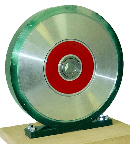 Fig. 3
– Electric machine
◄|| Photos of electric cars || | – Electric machine
◄|| Characteristics of electrical machines || |
Belashov modular low-speed generator MGB-300-144-2, created for technical devices, which convert a large moment of force, at low speeds, into electrical energy and can be used for wind engines, manual emergency power plants, damless hydroelectric power plants and so on...
In this design of a single-phase low-speed generator, two rows of multi-turn windings are used, but inside this generator you can place two more rows of multi-turn windings, making it two-phase, which will double the power of the generator. Depending on the number of modules, the consumer can independently assemble from individual modules any generator parameters for the required voltage, required current and a given number of revolutions.
The first question that buyers usually ask is the efficiency of low-speed generators, but they do not know that this value is uncertain, which depends on many parameters or quantities and, above all, on how the generator itself was made. I'll bring you specific example, how the efficiency of the generator is affected if the multi-turn stator windings are not manufactured correctly or with poor quality, since this part is very important and affects many characteristics of the low-speed generator.
When manufacturing multi-turn stator coils for a low-speed generator, it is necessary to take into account that there are rectangular or round wires and many types of windings, but in this case we will consider only three types of windings shown in Fig. 4:
Row winding of multi-turn windings pos. 1
Winding multi-turn windings in a checkerboard pattern, position 2
Winding multi-turn windings in a disorderly manner (in bulk) pos.3.
Fig. 4

Most important characteristic coil is the winding coefficient (the degree to which the winding space of a multi-turn coil is filled with copper) - the ratio of the copper area of the coil to the area of the winding space:
![]()
Where:
W is the number of coil turns,
Q - cross-section of wire with insulation, mm²
S - cross-sectional area of the winding window, mm².
It is necessary to take into account that it is very difficult to wind multi-turn stator windings with a thick wire, and even more so to create its exact profile for correct entry into the rotor magnetic system. Using a thinner wire, you can increase the winding coefficient, and using a parallel or series connection of the stator windings, you can bring the calculated cross-section of the wire to the required value. For example, in the stator of a single-phase low-speed generator MGB-300-144-2, There are two rows of multi-turn windings, which were wound randomly with a wire having a diameter of 0.29 mm (since I did not have the opportunity to make a row winding). The external multi-turn stator windings have 580 turns each. The internal stator windings consist of 360 turns. As a result, it turns out that the generator stator contains 16920 turns. This means that if on each multi-turn winding (taking into account the winding coefficient) we did not wind up at least 20 turns, then in the end it turns out that we could not wind up another 720 turns on our stator. If in each row of the stator of a low-speed generator there are two phases of two rows of multi-turn windings, then it turns out that we have lost 1440 turns, Fig.5.
Fig. 5

Usually the winding coefficient is in the range of 0.5 - 0.8, but you need to know that the higher the winding coefficient, the more better characteristics low speed generator. It is highest when staggered windings of multi-turn windings are used with self-sintered enameled wires. The advantage of these enameled wires is that they are glued together using varnish under the influence of heat or solvents. After sintering, a self-supporting winding is formed. The use of self-sintered enameled wires has an advantage in price and manufacturing, since winding frames, adhesive tape, compound and impregnating materials can be saved. Moreover, it is necessary to turn Special attention the fact that for better cooling of multi-turn windings, self-sintering enameled stator coils must be tightly adjacent through a heat-conducting dielectric to the aluminum body of a low-speed generator, since for normal operation of the generator, heat removal from multi-turn windings is main task, which affects the generator efficiency.
Manufacturers of low-speed generators for wind turbines, mini hydroelectric power plants or portable power plants must inform their customers of all the advantages and disadvantages of these machines. Buyers should know some important specifications of the generator:
The internal resistance of the multi-turn generator windings not only at 20°C, but also when the temperature of the multi-turn generator windings changes from 20°C to 80°C,
Current short circuit multi-turn generator windings at given speeds, not only at 20°C, but also when the temperature of the multi-turn generator windings changes from 20°C to 80°C, where only r o,
The operating current of the generator at a given number of revolutions, not only at 20°C, but also when the temperature of the multi-turn windings of the generator changes from 20°C to 80°C, where r o + r n,
When manufacturing a stator or rotor from a steel magnetic core on which multi-turn windings are installed, it is necessary to know the braking torque of the generator rotor,
Operating voltage of the generator, at given speeds,
Generator open circuit voltage (without any load),
A method for removing heat from multi-turn generator windings.
These technical characteristics are needed to match the internal resistance of the multi-turn windings of the generator with the load, since in order to obtain the greatest power in the external circuit, the load resistance must be equal to the internal resistance of the generator. For example, if the multi-turn windings of a generator have a large internal resistance, then this type generator is less susceptible to output voltage fluctuations. For a generator with low internal resistance, the output voltage drop can exceed 40%. There are other subtleties in choosing low-speed generators. For example, if the measurement technical characteristics generators were produced at a temperature of 20°C, then at a temperature of 70°C you may miss more than half of the power declared by the manufacturer, and so on... Let's prove this with specific examples.
A change in the temperature of the stator of a low-speed generator (as well as other electrical machines) causes a change in the resistance inside the multi-turn windings during its operation and even in the non-working position when the low-speed generator was installed on a wind turbine, which is located on the Sun.
This change in conductor resistance as a function of temperature, per each ohm of resistance of a given conductor when its temperature changes by 1°C, is called the temperature coefficient “alpha” (a). Thus, temperature coefficient characterizes the sensitivity of changes in conductor resistance to changes in temperature. In this case, we have copper windings, which have a temperature coefficient a = 0.004041.
For example, knowing the temperature coefficient of copper, we can determine the internal resistance of multi-turn stator windings, which occurred when the temperature of the stator, which heated up to 70°C in the Sun, changed.
The formula for determining the temperature coefficient looks like this:
Where:
R 1 – resistance of a given conductor at one temperature – T 1,
R 2 - resistance of the same conductor, but at a different temperature - T 2,
A is the temperature coefficient of the metal from which the conductor is made,
T 2 - final temperature of the windings from which the conductor is made, °C,
T 1 - initial temperature of the windings from which the conductor is made, °C.
1.
R 2 = R 1 + R 1 ∙ a ∙ (T 2 - T 1)
R 2 = 6 Ohm + 6 Ohm ∙ 0.004041 ∙ (70 – 20) = 7.2738 Ohm
Where:
R 1 – resistance of multi-turn stator windings at 20°C = 6 Ohm,
T 2 is the temperature of the stator of a low-speed generator heated in the Sun to 70°C.
Let us determine the current of a low-speed generator, at the terminals of which there is a voltage of 12 Volts at a temperature environment= 20°C.
Let us determine the current of a low-speed generator, at the terminals of which there is a voltage of 12 Volts at a temperature heated in the Sun to 70°C.
Let us determine the power of a low-speed generator, at the terminals of which there is a voltage of 12 Volts at an ambient temperature = 20°C.
P = U ∙ I = 12 V ∙ 2 A = 24 W
Let us determine the power of a low-speed generator, at the terminals of which there is a voltage of 12 Volts at a temperature heated in the Sun to 70°C.
P = U ∙ I = 12 V ∙ 1.6497566608925183535428524292667 A = 19.797079930710220242514229151192 W
Let us determine the drop in efficiency of a low-speed generator that is not working, but simply heated in the sun, when the temperature rises from 20°C to 70°C. This permissible temperature for the operation of electromechanical devices and units. If we even hypothetically imagine that the efficiency of a low-speed generator at 20°C was = 100% (which cannot be in nature), then we can find out what the power loss will be when the temperature of any electrical machines increases. Although many manufacturers of electric cars try to avoid these sensitive issues so as not to scare off their customers.
24 W = 100%
It follows from this that a low-speed generator, which has not even started working yet, has already lost 17.52% efficiency, and this will only happen if the internal stator resistance is small at low voltage on the stator windings. As the voltage at the generator terminals increases, the internal resistance of the generator increases accordingly, which will accordingly entail even more losses in the efficiency of the generator. At the same time, we are talking only about the active resistance of multi-turn stator windings, without including in the calculation the reactance of multi-turn stator windings, which is many times greater than the active resistance of the conductors. Let's consider a specific example when the voltage at the generator terminals is increased, which will entail an increase in the internal resistance of the multi-turn stator windings.
2. Let us determine the resistance of multi-turn stator windings with temperature changes:
R 2 = R 1 + R 1 ∙ a ∙ (T 2 - T 1)
R 2 = 12 Ohm + 12 Ohm ∙ 0.004041 ∙ (70 – 20) = 29.0952 Ohm
Where:
R 1 – resistance of multi-turn stator windings at 20°C = 12 Ohm,
R 2 – resistance of multi-turn stator windings at 70°C,
A – temperature coefficient of copper = 0.004041
T 1 - low-speed generator stator temperature at 20°C,
T 2 is the temperature of the stator of a low-speed generator heated in the Sun to 70°C.
Let's determine the current of a low-speed generator, at the terminals of which there is a voltage of 24 Volts at an ambient temperature = 20°C.
Let us determine the current of a low-speed generator, at the terminals of which there is a voltage of 24 Volts at a temperature heated in the Sun to 70°C.
Let us determine the power of a low-speed generator, at the terminals of which there is a voltage of 24 Volts at an ambient temperature = 20°C.
P = U ∙ I = 24 V ∙ 2 A = 48 W
Let us determine the power of a low-speed generator, at the terminals of which there is a voltage of 24 Volts at a temperature heated in the Sun to 70°C.
P = U ∙ I = 24 V ∙ 0.A = 19.7970799307102202425142291512 W
Let us determine the drop in efficiency of a low-speed generator that is not working, but simply heated in the sun, when the temperature rises from 20°C to 70°C.
48 W = 100%
19.797079930710220242514229151192 W = X%
This clear example, when a low-speed generator, when the voltage at the generator terminals increases and the internal resistance doubles, which, without even starting to work, has already lost 58.76% efficiency. As mentioned earlier, there was no mention here of the reactance of multi-turn stator windings, which is many times greater than the active resistance of the conductors. Because when the generator starts operating, the active and inductive resistance of the multi-turn stator windings begins to increase, which depend on the number of magnetic systems, the number of multi-turn windings, the method of their connection and the rotation speed of the rotor magnetic system. Therefore, if they offer you a low-speed generator, the power of which at 220 Volts exceeds 1000 W at 200 rpm, then draw your own conclusions...
It must be especially emphasized that, depending on the design of the stator or rotor, the multi-turn windings of the Belashov generator can be connected in such a way that the amplitude of the alternating current signal is pulsating.
The pulsating alternating current shown in Fig. 6, has the following advantages:
Reducing AC frequency,
Reducing heating of multi-turn windings,
Reducing the inductive reactance of multi-turn windings.
Fig. 6

Moreover, if a conventional single-phase alternating current generator, which is designed for 120 rpm, will produce a voltage of 12 V and have an alternating current signal frequency of 100 Hz, then when connecting multi-turn windings that produce a pulsating alternating current signal, the voltage and current will remain as usual single-phase generator, but the frequency of the alternating pulsating current will be 50 Hz.
On these small examples I clearly showed how one quantity can greatly influence the efficiency of a low-speed generator, but when developing generators or electrical machines there are many of them. For example, when calculating a low-speed generator, you can stretch one value to normal characteristics, while the other two can significantly worsen its parameters. Therefore, it is advisable to approach each wind turbine or mini hydroelectric power station individually and specifically manufacture a low-speed generator taking into account the ambient temperature, where it will work at the design load, taking into account the distance from the primary converters, and so on...
Consumers of low-speed generators should know other subtleties of this process. I'm sad to tell you, but there are not, and cannot be, low-speed generators in the world. In this case, you have a very powerful machine that is used at 5-30% of its intended capacity. For example, if you spin up a generator MGB-300-144-2, up to 2000 rpm, then we get 13833 W. Consumers begin to understand this incident when the moment of purchase occurs, where the price of the generator does not correspond to the declared power in relation to other electric machines. If we take a philosophical approach to the definition of the name, then for the rich it will be a low-speed generator, and for everyone else it will be a powerful electric car.
In order to produce a low-speed generator shown in Fig. 4 having:
Good cooling
Modular design,
High degree of reliability,
Reliable insulation resistance,
Small dimensions and light weight,
A generator that can be easily adjusted in current and voltage,
A generator that can be manufactured from a few W to hundreds of kW,
Dielectric stator of the generator which has no hysteresis losses,
Dielectric stator of the generator which has no eddy current losses,
Generator that can automatically detect the voltage of the incoming signal,
A generator whose dielectric stator has no losses due to armature reactance,
A generator having a monitoring and control system that is capable of automatically changing machine parameters,
Electric car direct current, which is capable of operating from one or more independent sources of various voltages and currents, and in southern countries from the energy of solar panels.
When manufacturing a low-speed generator, it is necessary to ensure that the wind turbine or mini hydroelectric power station itself, during operation, can change the design value of the generator by commutating the multi-turn windings of the stator or individual modules in such a way as to obtain the maximum power of the generated signal from the installation.
In order to produce a high-quality low-speed generator, it is necessary to obtain a technical specification from the customer for its development, which will help determine for what purposes this generator will be used. For example, we need a low speed generator for a wind power plant with a maximum power of 800 W at 400 rpm, and for this we need to know.
Approximate technical specifications for the development of a low-speed generator MGB-300-144-2.
1. Purpose. The low-speed generator is designed for a wind power plant in a separate individual house or a remote settlement that is located far from the central power grid.
2. Scope of application. Providing local electric lighting to power electrical household appliances, radio stations, televisions, radios, refrigerators and other low-power household consumers up to (500 - 800) W.
3. Technical characteristics and requirements for the generator.
3.1. Generator power at 400 rpm - 800 W.
3.2. Generator power at 300 rpm - 500 W.
3.7. Short circuit current at 50 rpm - 1.46 A.
3.8. AC frequency at 500 rpm - 100 Hz.
3.9. AC frequency at 300 rpm - 60 Hz.
3.11. The number of generator phases is one.
3.12. Excitation is magnetoelectric. Magnet material Nm30Di5k8rt with residual magnetic induction Br - 1.25 Tesla.
3.13. Ambient temperature from - 40°C to + 60°C.
3.14. The initial torque of the screw is no more than 0.02 kg∙m.
3.15. dimensions generator:
3.16. The outer diameter of the case is 320 mm.
3.17. Case length without shaft - 130 mm.
3.18. The length of the generator with shaft is 220 mm.
3.19. Generator weight no more than (to be specified).
3.20. Discharge voltage from the generator through a connector (the type of connector and its installation location are being specified).
3.21. System for automatic monitoring and regulation of changes in the design value of the generator (the type of system is being specified).
3.22. Design generator:
3.23. The generator is collapsible. The generator consists of a housing that houses four identical removable modules and one removable shaft.
3.24. The design of identical modules allows their use for both the first and second phases.
3.25. The generator housing is made in a closed design.
3.26. The number of multi-turn stator coils is 36 pcs.
3.27. Maximum voltage on one stator coil at 600 rpm. - 13 V.
3.28. Natural cooling method - IC 0041 GOST 20459-87.
3.29. Marine version - tropical, according to the degree of protection - IR 44 GOST 17494 - 87.
3.30. Insulation of current-carrying parts of the generator is class "B".
3.31. The generator operating mode is long-term (S1).
3.32. According to all requirements, the generator must comply with GOST 183 - 74.
3.33. When calculating and designing a generator, all technical characteristics and parameters of the machine may differ from terms of reference by 5 - 10%.
3.34. Individual clauses of the ToR can be clarified and supplemented by mutual agreement of the parties.
However, in order to draw up technical specifications for the development of a low-speed generator, it is necessary first of all to select the type of wind engine, make it advance paynemt and define:
Wind motor type,
Wind turbine wheel diameter,
Average annual air flow speed,
What power is it designed for? wind turbine,
Wind energy utilization rate of a wind turbine,
Torques of different types of wind turbines and so on...
In order to use air flow wind turbine, it is necessary to fully proceed from the fact that material point The base of the propeller of each blade, depending on the circumference of the wind turbine propellers, must travel a distance equal to the speed of the wind flow.
For example, let's calculate the number of revolutions of a low-speed generator when using a wind engine having:
Screw diameter 2 m,
Air flow speed = 6 m/s.
From the table located in the Patent Russian Federation № Let's determine the maximum power of the air flow at 6 m/s, which = 836.54 W.
Fig. 7
Let us determine the circumference around the wind turbine propellers, which is calculated by the formula:
L = P ∙ D
L = 2 m ∙ 3.1415926535897932384626433832795 = 6.283185307179586476925286766559 m
Where:
L – circumference,
D – circle diameter = 2 m,
P – ratio of the circumference to the diameter of the circle = 3.1415926535897932384626433832795.
Let us determine the time it takes for each wind turbine blade to travel around its axis at a wind speed of 6 m/s.
6 m/s: 6.283185307179586476925286766559 m = 0.s
Let's define maximum amount wind engine revolutions in one minute, with a wind speed of 6 m/s, knowing that 1 minute contains 60 seconds.
0.954929658551372014613302580235 rev/s = 1 sec
X rev = 60 sec
Let us determine the power of a wind turbine if, using a low-speed generator, we set the load on the wind turbine blades to 30% of the maximum power of the air flow.
836.54 W = 100%
X W = 30%
Let us determine the number of revolutions of the low-speed generator, which will change when the wind engine load is 30% of the maximum power of the wind flow.
836.54 W = 57.295779513082320876798154814 rpm
250.962 W = X rpm
In order to obtain a power of 250.962 W at a speed of 17.18873 rpm, it is necessary to install Belashov in a low-speed generator required amount modules.
From the technical characteristics it is clear that at 50 rpm one low-speed generator module produces 17 W of power.
Let us determine the power of the low-speed generator at 17.188733853924696263038846444 rpm.
50 rpm = 17 W
17.188733853924696263038846 rpm = X W
Let's determine the number of modules that, at 17.18873385 rpm, can provide power from a low-speed generator = 17 W.
5.84416951 W = 1 module
17 W = X modules
From preliminary calculations it is clear that to generate power 17 W at 17.18873385 rpm we need 3 modules.
IN in this example preliminary calculation of the wind turbine is not indicated:
Wind motor type,
Number of wind turbine blades,
The mass of the wind turbine blades and their shape,
The coefficient of propeller utilization at the declared speed of rotation of the wind wheel,
Wind turbine losses and much more...
For a complete calculation of wind turbines, see the Patent of the Russian Federation №
Currently there are no manufacturers producing in-house full set equipment for wind turbines or mini hydroelectric power stations, which will be tied to the actual terrain and specific conditions. These companies buy ready-made components from different manufacturers and assemble finished product and sell to consumers. Even if the wind turbine is very good, it may not be suitable for a particular area or given climate conditions. With low-speed Belashov generators, the situation is better, since from individual modules you can assemble any parameters of the generator for any voltage, current and number of revolutions, where during operation you can change the design value of the generator. They are much more economical in production, since they can be offered to consumers from a set of identical modules various parameters low speed generator.
After this, taking into account the received technical specifications, it is necessary to carefully calculate and develop each part of the low-speed generator:
Stator with multi-turn windings (taking into account the temperature change of multi-turn windings),
The number of multi-turn stator windings and the electrical diagram of their connection,
The shape of multi-turn stator windings and the method of removing heat from them,
The shape of magnets and magnetic cores of the rotor magnetic system,
Device for convergence of rotor magnetic systems,
Generator housing,
Generator shaft,
Unfortunately, I did not have like-minded people and, in addition to inventions, I had to do all the calculations, developments, design, and production of generators and other electrical machines myself.
In my opinion, all small-scale energy is developing in the wrong direction. The main strategic misconception is that any wind turbines or mini hydroelectric power stations should not produce the finished product on site, namely the voltage and power that the consumer declares. Alternative energy itself must receive as much energy of any type as possible at primary points and then be transferred to the consumer without unnecessary losses, where electrical signal must be converted on site into a finished product for use by the consumer. Nowadays they receive the finished product on site and send it to the consumer with great losses.
As we see from previous examples, this is not the right approach to the development of low-speed generators, wind turbines and mini hydroelectric power stations. In order to correctly install a wind turbine or mini hydroelectric power station, you need to start with a thorough inspection of the installation site, and then make a thorough calculation of all the components and components, then you will get what you thought about.
In conclusion, we can say that small wind power and small hydro power are largely discredited in the eyes of consumers against the backdrop of unscrupulous manufacturers and managers who are poorly versed in technology. Many manufacturers promise big profits that can come from alternative energy, but forget to talk about the problems that consumers of these generating plants can expect.
A video demonstrating the operation of the cassette-modular low-speed generator MGB-205-72-1.
In this video, a 40-watt incandescent lamp at 12 volts is used as a load.
The cassette-modular low-speed generator MGB-205-72-1 was demonstrated at the sixth international exhibition of electrical products and new technologies "Electro - 96" held from July 2 to July 6, 1996 at the Expocenter of the Russian Federation in Moscow.
It must be especially emphasized that after a certain amount of time or long-term continuous operation, the magnetic system of the low-speed generator, consisting of permanent magnets, begins to weaken and crumble. If, when rotating at 45 rpm, Belashov’s cassette-modular low-speed generator MGB-205-72-1 in 1996 showed a bright burning of a 60-watt incandescent lamp at a voltage of 12 volts, then in 2019 it can barely cope with a 40-watt light bulb. Some magnet manufacturers have guaranteed the permanent magnets they produce for 20 years, which practically confirms their commitment.
A video demonstrating the operation of one module of the Belashov MGB-300-84-2 low-speed generator.
A video demonstrating the operation of one module of the Belashov MGB-340-84-1 low-speed generator.
In this video, a 60-watt incandescent lamp at 12 volts is used as a load.
A video demonstrating battery charging from a Belashov MGB-340-84 low-speed generator.
A 12 Volt battery is used as a load. Belashov's low-speed generator MGB-340-84-1 at 30-40 rpm provides a charging current of at least one Ampere.
Video about the mechanism of formation of a magnet and a magnetic system from atoms of magnetic material.
The video is dedicated to the mechanism of formation of a magnet and a magnetic system from atoms of magnetic material.
Video about the world's first electric disk machine, Belashov MDEMB-01.
The world's first disk electric machine, Belashov MDEMB-01, in which one or many multi-turn windings of a disk dielectric rotor, without changing the direction of the current in the conductors, pass through one or many permanent horseshoe magnets. The magnets of the poles of the stator excitation system, which are located in the same row, can have different directions of movement of magnetic fluxes. Belashov's disk dielectric machine MDEMB-01 was shown on the first channel of central television in 1993.
The fact that a generator using neodymium magnets, for example a wind generator, is useful is no longer in doubt. Even if it is not possible to provide energy to all the appliances in the house in this way, it will still show its advantage with prolonged use. Making the device yourself will make operation even more economical and enjoyable.
Characteristics of neodymium magnets
But let's first find out what magnets are. They appeared not so long ago. It has been possible to purchase magnets in stores since the nineties of the last century. They are made of neodymium, boron and iron. The main element, of course, is neodymium. It is a metal of the lanthanide group, with the help of which magnets acquire enormous adhesive force. If you take two pieces big size and attract each other, it will be almost impossible to disengage them.
Mostly, of course, there are miniature species on sale. In any gift shop you can find balls (or other shapes) made of this metal. The high price of neodymium magnets is explained by the complexity of extracting raw materials and the technology of their production. If a ball with a diameter of 3-5 millimeters will cost only a few rubles, then for a magnet with a diameter of 20 millimeters and above you will have to pay 500 rubles or more.
Neodymium magnets are produced in special furnaces, where the process occurs without oxygen, in a vacuum or atmosphere with inert gas. The most common are magnets with axial magnetization, in which the field vector is directed along one of the planes where the thickness is measured.
The characteristics of neodymium magnets are very valuable, but they can easily be damaged beyond repair. So, a strong blow can deprive them of all their properties. Therefore, you need to try to avoid falls. Also different types has its own temperature limit, which varies from eighty to two hundred and fifty degrees. At temperatures above the limiting temperature, the magnet loses its properties.
Proper and careful use is the key to maintaining quality for thirty years or more. Natural demagnetization is only one percent per year.
Application of neodymium magnets
They are often used in experiments in physics and electrical engineering. But in practice, these magnets have already found wide application, for example, in industry. They can often be found as part of souvenir products.
Their high degree of traction makes them very useful when searching for metal objects found underground. Therefore, many search engines use equipment using neodymium magnets to find equipment left over from war times.
If old acoustic speakers If they barely work, sometimes it’s worth adding neodymium magnets to the ferrite magnets, and the equipment will sound great again.
Likewise, you can try replacing the old magnets on the engine or generator. Then there is a chance that the technology will work much better. Consumption will even decrease.
Humanity has been searching for a long time. On neodymium magnets, as some believe, the technology may well take on real shape.
Finished vertically oriented wind generator
To wind generators, especially in last years, interest was renewed again. New models have appeared, more convenient and practical.

Until recently, they were mainly used horizontal wind generators having three blades. A vertical views did not spread due to the heavy load on the wind wheel bearings, as a result of which increased friction arose, absorbing energy.
But thanks to the use of the principles, a wind generator on neodymium magnets began to be used precisely vertically oriented, with pronounced free inertial rotation. Currently, he has proven his more high efficiency compared to horizontal.
An easy start is achieved thanks to the principle of magnetic levitation. And thanks to the multi-polarity, which gives the rated voltage at low speeds, it is possible to do away with gearboxes completely.
Some devices are capable of starting to work when the wind speed is only one and a half centimeters per second, and when it reaches only three to four meters per second, it can already be equal to the generated power of the device.
Application area
Thus, a wind generator, depending on its power, can provide energy to different buildings.
City apartments.
Private houses, cottages, shops, car washes.
Kindergartens, hospitals, ports and other city institutions.
Advantages
Devices are purchased in finished form or make it yourself. Having purchased a wind generator, all that remains is to install it. All adjustments and alignments have already been completed, tests have been carried out under various climatic conditions.
Neodymium magnets, which are used instead of a gearbox and bearings, allow you to achieve the following results:
friction is reduced and the service life of all parts is increased;
vibration and noise of the device during operation disappears;
the cost decreases;
energy is saved;
There is no need to regularly service the device.
A wind generator can be purchased with a built-in inverter that charges the battery, as well as a controller.

Most common models
The generator with neodymium magnets can be manufactured with a single or double mount. In addition to the main neodymium magnets, the design may include additional ferrite magnets. The height of the wing varies, usually from one to three meters.
More powerful models have double fastening. They also install additional generators on ferrite magnets and have different height wing and diameter.
Homemade designs

Considering that not everyone can afford to buy a generator with neodymium magnets powered by wind, they often decide to build the structure with their own hands. Let's consider various options devices that you can easily make yourself.
DIY wind generator
Having a vertical axis of rotation, it usually has from three to six blades. The design includes a stator, blades (stationary and rotating) and a rotor. Wind affects the blades and the entry and exit of the turbine. Car hubs are sometimes used as a support. This neodymium magnet generator is silent and remains stable even in strong winds. He doesn't need a tall mast. Movement begins even in very light winds.

What could be the design of a stationary generator?
It is known that electromotive force through a wire is generated by changing magnetic field. The stationary generator core is created by electronic control, not mechanically. The generator controls the flow automatically, acting resonantly and consuming very low power. Its oscillations deflect the magnetic fluxes of iron or ferrite cores to the sides. The higher the oscillation frequency, the stronger the generator power. Starting is realized by a short-term pulse to the generator.
How to make a perpetual motion machine
Neodymium magnets are basically the same type in terms of their operating principle. The standard option is the axial type.
It is based on a car hub with brake discs. Such a base will become reliable and powerful.
When deciding to use it, the hub should be completely disassembled and checked to see if there is enough lubrication, and if necessary, clean off the rust. Then the finished device will be pleasant to paint, and it will take on a “homey”, well-groomed appearance.

In a single-phase device, the number of poles must be equal to the number of magnets. In three-phase, the ratio of two to three or four to three must be observed. Magnets are placed with alternating poles. They must be precisely located. To do this, you can draw a template on paper, cut it out and accurately transfer it to the disk.
To avoid mixing up the poles, make notes with a marker. To do this, magnets are brought on one side: the one that attracts is designated with a “+” sign, and the one that repels is marked with a “-”. Magnets must attract, that is, those located opposite each other must have different poles.

Usually superglue or something similar is used, and after sticking it is filled with more epoxy resin to increase strength, after making “borders” so that it does not leak out.
Three or single phase
A generator based on neodymium magnets is usually designed to operate with vibration when under load, since a constant current output will not be ensured, which will result in an abrupt amplitude.
But with a three-phase system, constant power is guaranteed at all times thanks to phase compensation. Therefore, there will be no vibration or buzzing. And the operating efficiency will be fifty percent higher than with one phase.
Winding the coil and the rest of the assembly
Calculation of a generator using neodymium magnets is mainly done by eye. But it is better, of course, to achieve accuracy. For example, for a low-speed device, where battery charging would begin to function at 100-150 rpm, from 1000 to 1200 turns will be required. Total divided by the number of coils. How many turns will be required in each of them. The coils are wound with the thickest possible wire, since with less resistance the current will be greater (with a high voltage the resistance will take up all the current).
Usually round ones are used, but it is better to wind coils elongated shape. Inner hole must be equal to or greater than the diameter of the magnet. In addition, the optimal magnet will be in the form of a rectangle rather than a puck, since in the former the magnetic field is stretched along its length, while in the latter it is concentrated in the center.
The thickness of the stator is made equal to the thickness of the magnets. You can use plywood for the form. Fiberglass is placed on its bottom and on top of the coils for strength. The coils are connected to each other, and each phase is brought out to be connected then with a triangle or star.
All that remains is to make a mast and a reliable foundation.
Of course, this is not a perpetual motion machine based on neodymium magnets. However, savings when using a wind generator will be ensured.
Sent by:
Homemade windmill with generator. Of interest is mainly the type of generator. This design is very common and simple, however, it has not yet been presented on our website.
Author Burlaka Viktor Afanasyevich.
I did a photo shoot of my little windmill or, as I call it, a working model. Since I built it unexpectedly for myself, I just decided to practice and find out what would happen. At first I didn’t photograph anything, I didn’t think that they might be interested in it, the photo shoot turned out in the reverse order, i.e. deduction - from the whole to the parts.
And now a little history, and everything in order:
Building a wind turbine has been my long-time dream, but there were many obstacles. He lived in a city apartment, but there was no dacha. Then moving from one city to another, then to a third. I have been living in Svetlovodsk for the last 18 years. All the conditions are here - private cottage for two families, 5 acres of vegetable garden and the same amount of garden. To the east and south there is open terrain, to the north and west the terrain is higher than mine. The winds are not kind, i.e. not very strong. Well, I think I'll build a windmill here for the soul.
But when I got serious, it turned out to be not so simple. I did not find any suitable literature. For a long time I couldn’t decide on a generator; I didn’t know how to make the blades correctly, what gearbox to use, how to protect it from a hurricane, etc. As they say, it was stewed in its own juice. But I knew that if I really wanted it, everything would work out.
I slowly made the mast. Using ferrous metal, I selected suitable pieces of pipe, starting with a diameter of 325 mm and 1.5 m long (to fit in the trunk of my car). In exchange, he sold scrap metal. The result was a mast 12 m long. For the foundation I brought a defective foundation block from high voltage support. I buried it 2 meters into the ground and 1 meter remained above the ground. Then I scalded it with two belts from the corner and welded brackets to them. At the ends of the brackets, I welded “plates” of 16mm iron measuring 50 x 50 cm to the anchor bolts, connected to each other by powerful hinges. I bought soft 10 mm cables and turnbuckles on the market, everything is anodized and does not rust. I welded and buried an anchor under the removable winch. The winch also had to be made homemade, using a ready-made worm gear. In addition, I installed a U-shaped support about 2 m high, on which the mast should rest. Since there was nowhere to rush, the mast was made without haste and therefore, in my opinion, it turned out beautiful and reliable.
And then God, seeing my work, blessed me to go to the forum http://forum.ixbt.com/topic.cgi?id=48:4219-74#1829. I re-read it all, registered, and began to gain experience. I started remaking a self-generator, and when I translated from English “overseas” sites (Hugh Pigot and others) on building end-mounted generators without iron in the coils, I really wanted to try and do it myself, at least in miniature.

General view of the windmill

Generator

Generator, side view.

Wire output.


Blades, housing and disassembled generator.
I decided to build a working smaller model that would deliver up to 1 amp per 12-volt battery.
To make the rotor, I bought 24 pieces in Znamenka at the Acoustics company. neodymium disk magnets 20*5 mm. I found a hub from a walk-behind tractor wheel, the turner, according to my drawings, turned two steel disks with a diameter of 105 mm and a thickness of 5 mm, a spacer sleeve with a thickness of 15 mm, and a shaft. I glued magnets, 12 each for each, and filled them halfway with epoxy, alternating their polarity.

To make the stator, I wound 12 coils of enamel wire with a diameter of 0.5 mm, 60 turns per coil (I took the wire from the demagnetization loop of an old unusable color picture tube, there is enough of it). I soldered the coils in series, end to end, beginning to beginning, etc. ( Here I “don’t understand”, if it’s possible to connect everything in series to get one phase? It is advisable to check during manufacture. Editor's note) It turned out to be one phase (I was afraid that there would be too little voltage). I cut out a shape from 4 mm plywood and rubbed it with wax.

It's a pity that the complete form has not been preserved. I put wax paper on the bottom base (I stole it from my wife in the kitchen, she bakes on it), and placed a mold on it with a round piece in the center. Then I cut out two circles from fiberglass. One laid on wax paper the bottom base of the mold. I laid out the coils soldered together on it. The leads from the stranded insulated wire were laid into shallow grooves cut with a hacksaw. I filled it all with epoxy. I waited about an hour for the air bubbles to all come out and the epoxy to spread evenly throughout the entire mold and saturate the coils, top up where necessary, and cover with a second circle of fiberglass. Place a second sheet of wax paper on top and press it with the top base (a piece of chipboard). The main thing is that both bases are strictly flat. In the morning I disconnected the mold and removed a beautiful transparent stator 4mm thick.

It’s a pity that epoxy is not suitable for a more powerful windmill, because... fears high temperature.
I inserted 2 bearings into the hub, a shaft with a key in them, the first rotor disk with magnets glued and half filled with epoxy, then a spacer sleeve 15mm thick. The thickness of the stator with filled coils is 4mm, the thickness of the magnets is 5mm, a total of 5+4+5=14mm. On the rotor disks, 0.5 mm edges are left on the edges so that the magnets rest against centrifugal force (just in case). Therefore, we will subtract 1mm. 13mm left. There is 1mm left for the gaps. Therefore the spacer is 15mm. Then the stator (a transparent disk with coils), which is attached to the hub with three 5 mm copper bolts, they can be seen in the photo. Then a second rotor disk is installed, which rests on the spacer sleeve. You need to be careful not to get your finger caught under the magnets - they get pinched very painfully. (Opposite magnets on the disks must have different polarities, i.e. attract.)

Sketch of a wind turbine.
The gaps between the magnets and the stator are adjusted by copper nuts placed on copper bolts on both sides of the hub.
A propeller is put on the remaining protruding part of the shaft with a key, which is pressed to the rotor with a nut through a washer (and, if necessary, a bushing) and a bushing. It is advisable to cover the nut with a fairing (I never made one).

But I made a canopy roof over the rotor and stator by sawing an aluminum pan so as to cover part of the bottom and part of the side wall.

The propeller was made from a meter-long piece of duralumin irrigation pipe with a diameter of 220 mm and a wall thickness of 2.5 mm.
I simply drew a two-bladed propeller on it and cut it out with a jigsaw. (From the same piece I also cut out three blades 1 m long for a windmill on a self-generator, and as you can see, there are still some left). I rounded the leading edge of the blades “by eye” with a radius equal to half the thickness of the duralumin, and sharpened the rear edge with a chamfer of approximately 1 cm at the ends and up to 3 cm towards the center.
In the center of the propeller, I first drilled a hole with a 1mm drill for balancing. You can balance it directly on the drill, placing the drill on the table, or hang it on a thread from the ceiling. You need to balance very carefully. I balanced the rotor discs and the propeller separately. After all, the speed reaches 1500 rpm.
Since there is no magnetic sticking, the propeller rotates happily from the slightest breeze, which you can’t even feel on the ground. During operating wind it develops high speeds, I have a 2A direct-connection ammeter, so it often goes off scale with a 12 volt old car battery. True, at the same time the tail begins to fold and rise upward, i.e. automatic protection against strong wind and excessive speed.
The protection is made on the basis of the inclined axis of rotation of the tail.

The axis deviation is 18-20 degrees from the vertical. I apologize for the drawing, I tried to copy it from an overseas site http://www.otherpower.com/otherpower_wind.html
This windmill worked for me for 3 months. I took it off and disassembled it - the bearings are fine, the stator is also intact. The magnets are a little rusty in places where the paint did not get on. The cable goes directly without a current collector. I have it made, but I changed my mind about installing it. When I dismantled the small windmill, it was not twisted. So I was convinced that it is not needed, only extra hassle. It produced up to 30 watts of power. Propeller noise when closed windows inaudible. And when open it’s not very audible, if healthy sleep, it won’t wake you up, especially against the background of the noise of the wind itself.
There is a desire to make a large one using the same scheme, although the stator needs to be made differently, not using epoxy. I'm thinking about this now. In the meantime, during these three months, I built a windmill using a three-bladed self-generator with a diameter of 2.2 m and a power of about 400 watts. About him in the next article.
Wind generator based on a homemade axial disk generator. I built it a couple of years ago.
The design of this generator is the first thing you find on the network of practical models of wind turbines. In a narrow circle we call them bourgeois. It was they who began to use this generator layout, due to the availability of rare earth magnets. Now in our country this model is repeated quite often.
At first glance, this is the most affordable design. This is partly true, but the efficiency of iron-free stators is much lower than those with iron. For such generators, magnets are needed thicker, and the quantity is twice as large. So, more about the essence of the project.
The generator has 16 pairs of poles. The magnets used were neodymium disk. Diameter 27 mm, height 8 mm. Very serious stuff. Serious injury may occur if handled carelessly! 12 coils were used. Three-phase generator. Star connection.
To wind the coils, 0.9 mm wire was used, although the calculation was made for 1.06 mm wire. But he was not there at that time. For this reason, there is empty space between the coils, and the generator has not reached its design parameters. I wound the coils on a homemade machine. Nothing special.
The design can be absolutely anything. 


For the stator, a plywood mold was made. 

After treating the mold with Vaseline (necessary so that the cast stator can be easily removed from the mold), I positioned the coils.
Soldered accordingly. 


Divorced epoxy resin with the addition of 30% talc (baby powder). I put fiberglass mesh on the bottom of the mold and on top of the coils, since it is more convenient for me to work with it than with fiberglass. I poured the stator, gradually adding resin so that air bubbles came out.
In order to tighten the cover, I marked it so that the screws would pass through the hole in the coil (so as not to damage it). I covered the coil hole with plasticine (removed it after drying) for better cooling.
The next day, I removed the finished stator from the mold without any problems. It turned out smooth and beautiful.


To make the rotor, I took the rear hub assembly from a VAZ 2108. It's not expensive and quite powerful. At the car service they gave me brake discs, again from eight (nine). Discs diameter 240 mm. thickness 10 mm. Having polished work surface, glued magnets. I glued it with superglue, then filled it with epoxy resin.


I welded the wind head and attached the generator to it. The tail is rigidly fixed, that is, storm protection is not performed.


Blades from PVC pipes diameter 160 mm. I made both a three-bladed version and a five-bladed one. Both options worked fine.


Some conclusions.
Charging the battery begins almost as soon as it starts to rotate (and it rotates from any blow). 1-2 amps from a light breeze, with small gusts 4-5 amps. With normal winds around 10 A.
Conclusion: the goal has been achieved (charging the battery in light winds).

In strong winds I recorded 20 A, the device does not show more.
This model has now been dismantled. Upon inspection, no damage was found, although everything was not even painted.
I plan to do some experiments with it.
Well, here are the actual bullying that I was talking about.
I want to check one more option. Use annealed iron filings instead of ets in the generator stator.
The sawdust is neither small nor large.
Since everything was done under very limited time conditions, and the temperature was 10, no matter how it contributed to the feat of labor, the results were appropriate. Again, a ready-made stator was used, which was not intended for this. However, everything is in order. The photo shows the whole process. I mixed sawdust not with epoxy, but with silicone sealant.
The result was a plastic mass that was easy to work with.


And a test table for this option. 
I think this option, carried out according to all the rules, will give a completely working option.
In our age of computer technology and high technology, many have begun to think about alternative sources energy - after all, the riches of the earth’s interior are not limitless. The idea of using the energy of the movement of air masses as such a source is far from new, but only in our time is it beginning to take on more obvious (from the point of view of practical use) outlines. Now, thanks to the use of new technologies and construction materials, it has even become possible to purchase (or manufacture) such installations for use by private individuals - for a wind turbine installed for a house on the territory of a neighboring summer cottage crowds of onlookers no longer come to stare - such a sight is beginning to become almost commonplace.
Some components and assemblies of wind turbines have changed radically. If earlier a windmill generator was a standard design with brush or ring current collectors, which were quite noisy during operation (so installing such a unit in the residential sector was considered impossible), now, with the advent of heavy-duty neodymium magnets,

which lose only about 1 percent of their power over 10 years, it has become possible to manufacture single- or three-phase generators operating almost silently and with minimal wind loads (0.5-2.5 m/s). Serious innovations have also appeared in the field of wind wheel design. If previously the design of a wind generator with a parallel (relative to the Earth) arrangement of the axis of rotation was widely used,

Nowadays, designs using an axial vertical windmill are becoming increasingly popular.

The use of this design is due to several factors: the blades of a wind wheel with a horizontal axis of rotation, directed towards the air flow and cutting it, create high level noise (about 70, and in some cases more, decibels); to “start” a generator equipped with such a wind wheel, a fairly strong air flow is required - about 8-10 m/s (try to find an area on the planet where the wind would constantly blow at such a speed!), as a result - the use of tall masts to locate such structures; to install the wind wheel “downwind”, the use of special “steering” mechanisms is required; In addition, a braking system is needed in case of strong winds. The design of an axial wind generator with vertical axis rotation (see photo). The structure does not need to be raised high above the ground - 1-4 meters is enough (for a 1.5 kW generator); the height of the wind wheel blade is approximately 1 meter (versus 3 for a generator of the same power, but with a horizontal propeller axis); To rotate such a unit, at which it is capable of delivering sufficient power to the load, a light breeze (1.5 m/s) is enough. All these factors are a reliable prerequisite for purchasing or independently manufacturing such wind turbines for your home.

The resulting energy can be easily used for household purposes directly (using an inverter) and stored (batteries). The power (number) of wind turbines and batteries can be calculated using simple formulas: Wtotal = Wload * (1.3 or 1.5) - this value depends on the “wind resources” of your area. The number of required batteries can also be approximately calculated by multiplying the power (W) consumption you need per day by the number of windless days. In addition, home heating schemes using wind generators have appeared in the practice of home-made workers, where the load is low-voltage heaters (heating elements) immersed in an energy-intensive coolant. The use of hybrid alternative energy supply schemes, with the combined use of wind generators and solar panels, is also considered advisable - see our announcement article “Solar batteries”. In conclusion, I would like to give a small but very important note: at self-production wind generators, follow safety rules when working with powerful neodymium magnets - a damaged TV, a deformed refrigerator door or your favorite car is not the worst thing. Much more terrible are crushed finger bones, sandwiched between two magnets, or hands pierced by sharp metal tools - it’s not very pleasant when a knife lying on a workbench suddenly takes off and from a distance of half a meter sticks into your hand, in which the magnet is located. Do not heat or apply strong shock loads to magnets - heating (as a result of processing) leads to loss of magnetic properties, and strong heating leads to ignition, releasing toxic substances. What, did we scare you? Don’t be sad - following all the above rules will allow you to avoid injuries and damage to property, and the unit manufactured for your home will delight you with its trouble-free operation! Author of the article: Elektrodych.