LEDs recent times are considered one of the most common light sources. However, not so long ago, its use was limited only to indicative properties. With the development of technology and optics, this electron-hole junction semiconductor device has taken a leading position in the creation and organization of safe, economical, and environmentally friendly lighting. Its luminous flux lies in a narrow range of the spectrum and appears only when the current passes in a certain direction. The LED operates only on constant voltage, and when not correct connection can easily fail. This is where one of the absolutely logical questions arises - how to determine the polarity of the LED?
Determining the polarity of LEDs can be done in several ways:
- Visually;
- By using measuring instrument(tester, multimeter, ohmmeter);
- By supplying voltage from a power source;
- Finding this device in the manual or in the accompanying technical documentation;
All these methods are simple, effective and even a person without electrical education can use them.
Visual definition
 How to determine the polarity of an LED visually, because this is the simplest way that does not require special devices. In electronics, there are several types of packages in which this semiconductor device is manufactured. One of the common types of LEDs is a small electronic device of a cylindrical body, the diameter of which ranges from 3.5 mm and more.
In order to determine its polarity, that is, to which terminal to connect the plus, and to which minus, from a constant voltage source, you need to carefully consider the LED itself. In this case, you can see through the transparent surface that the area of the cathode (negative terminal) is much larger than the anode (positive). Even if it is impossible to see a larger electrode inside the body of a cylindrical LED, then the leads from it will also differ in size, and the negative one will be more massive.
 Also in the latest models of LED luminaires, you can find SMD LEDs, which are used for surface mounting. They are widely used in both LED lamps, spotlights, and in special tapes. Such light sources have a special bevel or, as it is called, a key that indicates the negative electrode of the connection - the cathode.
However, on some SMD LEDs, you can see, upon careful external examination, a special symbol, which will indicate its polarity. It should also be noted that the more powerful the LED, the larger and more massive it is, which means that determining where its cathode is, and where the anode will be easier during visual inspection.
Determination with a multimeter
 Most radio amateurs at least somehow connected with electricity have multimeters in their arsenal, which can be either dial or digital. It is with them that you can easily and accurately determine the polarity of the LED, and also check its performance. This type of check is performed with a multimeter (tester) in ohmmeter mode.
To do this, you need to find out which of the tester probes contains a negative and which positive potential. If you connect the probes of the measuring device in the forward direction (that is, the anode of the LED will be connected, respectively, to the positive probe, and the cathode to the negative one), the readings of the device will show some resistance value in Ohms. If you swap the probes, a serviceable LED will show a fairly high resistance, which can be several hundred kΩ or, in general, infinity. When using and checking some LEDs low power and with the correct (direct) connection, you can even see a small glow between the anode and cathode. This is also a very good sign that the LED is not only working and ready to work, but also its polarity coincides with the polarity of the ohmmeter probes.
Determination by applying voltage
 Excellent results are also shown by the method of determining the polarity of the LED by applying a small voltage. This method, like the previous one, allows you to determine not only the polarity, but also the health of the element. You will need a source to verify direct current, it can be a battery, a rechargeable battery or a power supply. The optimal and safest for a LED is a power supply with a continuously variable output constant voltage.
If the connection is correct, then when the voltage rises to 3-5 volts, the LED will emit a luminous flux, the saturation and strength of which will depend on the power of the LED. If, when connecting, the polarity of the power source and the polarity of this semiconductor device do not match, then the LED will not even glow a little, so you should not raise the voltage more than 5 volts so as not to damage it. It is also recommended in series with a current-limiting resistor with a resistance from 600 Ohm to several kOhm, this will additionally protect the LED from high current, and therefore from breakdown.
Determination of polarity using technical documentation
A fairly large amount of information about this semiconductor device can be found in the technical documentation provided by the manufacturer. It indicates not only the limits of the operating voltage and current, but also data such as weight, dimensions and many more electronic parameters that may not be entirely clear. Of course, when buying one LED, no one will give such information, this will require large quantities of goods. Sellers in specialized stores do not always give necessary information, for this at least you need to find out the brand of this LED, and then find its parameters and characteristics either on the Internet or in special reference books.
In any case, you need to understand that only by observing the correct polarity of the LED and others electrical parameters, this semiconductor device will serve for a long time, because it is not afraid of frequent switching on and off, or exposure external factors such as temperature or dust.
Video about determining the polarity of LEDs

Surely, those who have just started to deal with electronics are familiar with the LED and imagine what it is. For those who have a vague idea of what a light-emitting diode is, this article has been written.
LEDs are currently actively (one might say, overactive) used in both household and industrial radio electronic equipment. Since the 70s of the twentieth century, LEDs have become more actively used in radio electronics, since the technologies of those years made it possible to start mass production of LEDs, and, therefore, sell LEDs at affordable prices.
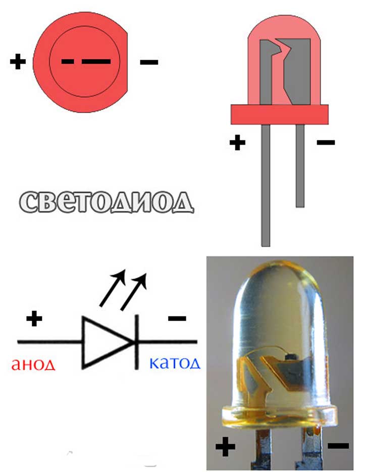
On schematic diagrams a regular LED is indicated like a semiconductor diode, but in a circle. To indicate that it is the emitting diode that is depicted, two arrows are drawn next to the conventional image, directed from symbol diode.

LED symbol
How to “light up” the LED?
First you need to find or buy on the radio market the most common 3-volt LED of any glow color, whoever you like. Since the LED is semiconductor p-n transition, then it, like a regular diode only passes current in one direction... This should be taken into account when connecting power to the LED.
To power the LED, you need a 3 volt power supply. In the simplest case, a 3-volt flat lithium battery is suitable - these are often used to power the remotes of car radios and car CD / MP3 players.

The positive terminal of the battery is connected to the anode terminal of the LED, and the negative terminal to the cathode terminal of the LED. Find out where the cathode (negative terminal) of the LED, and where the anode (positive terminal) is in several ways.
For new, just purchased LEDs, the leads are not yet shortened (during installation, for example) and the longest lead is the anode. Shorter, hence the cathode.
Also, on the side of the cathode terminal, the plastic case of the LED has flat serif on the butt end.
If the body of the LED is made of transparent plastic, then it is not difficult to visually determine that the light-emitting crystal is placed on the electrode, on the edge of which there is a kind of cup, in which the light-emitting crystal is located. The output of the electrode with the "cup" is negative (cathodic). A thin "tendril" leaves the crystal - a thin wire that is connected to anode LED output.
You should not be afraid of polarity reversal when connecting the LED power supply, in the worst case, the LED simply will not light up. True, if the LED is part of a complex electronic device, then the consequences of incorrect inclusion of the LED in the circuit should be taken into account.
What you should be afraid of when connecting an LED is that the supply voltage is exceeded, as this leads to heating and destruction of the LED crystal. In most cases, a burned-out LED can be easily identified by appearance... When the LED burns out, in the place where the light-emitting crystal is located, a black spot that is clearly visible to the eye is formed - this is burnt crystal.
You can check the health of the LED using widespread multimeters series DT-83x, MAS-83x and the like, as well as improve an existing multimeter by integrating an LED flashlight into the device.
Any DIY and electronics lover uses diodes as indicators, or as lighting effects and lighting. In order for the LED device to glow, you need to connect it correctly. You already know what the diode is conducting. Therefore, before soldering, you need to determine where the anode and cathode of the LED are.
You can find two LED symbols on the schematic diagram.
The triangular half of the designation is the anode, and the vertical line is the cathode. The two arrows indicate that the diode is emitting light. So, the diagram indicates the anode and cathode of the diode, how to find it on a real element?
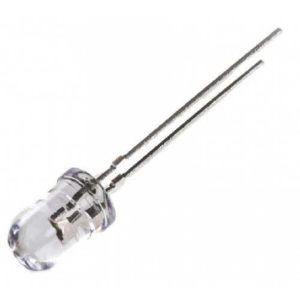
5mm diode pinout
To connect the diodes as in the diagram, you need to decide where the plus and minus of the LED are. First, let's look at the example of common low-power 5 mm diodes.

The figure above shows: A - anode, K - cathode and schematic designation.
Pay attention to the flask. Two parts can be seen in it - this is a small metal anode, and a wide part that looks like a bowl is a cathode. The plus is connected to the anode, and the minus to the cathode.
If you are using new LED elements, it is even easier for you to pinout them. The length of the legs will help determine the polarity of the LED. Manufacturers make short and long legs. The plus is always longer than the minus!
If you are soldering a non-new diode, then the plus and minus is the same length. In this case, a tester or a simple multimeter will help determine the plus and minus.
How to determine the anode and cathode of diodes 1W or more
In 5mm floodlights, samples are used less and less, they were replaced by powerful elements with a capacity of 1 watt or SMD. To understand where the plus and minus are on powerful LED, you need to carefully look at the element from all sides.

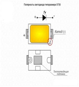
The most common models in such a case have a power of 0.5 watts. In the figure, the polarity mark is circled in red. In this case, the plus sign marks the anode of the 1W LED.
How do I know the polarity of an SMD?
SMD is actively used practically in any technique:- Light bulbs;
- LED strips;
- flashlights;
- indication of something.
You won't be able to see their insides, so you need to either use devices for testing, or rely on the LED case.
For example, the SMD 5050 case has a corner mark in the form of a cut. All leads located on the side of the label are cathodes. There are three crystals in its body, this is necessary to achieve a high brightness of the glow.

A similar designation for SMD 3528 also indicates the cathode, take a look at this photo of the LED strip.

The marking of the SMD 5630 pins is similar - the cut indicates the cathode. It can also be recognized by the fact that the heat sink on the bottom of the case is displaced towards the anode.

How to determine a plus on a small SMD?
In some cases (SMD 1206), you can find another way to indicate the polarity of LEDs: using a triangle, U-shaped or T-shaped pictogram on the surface of the diode.
The protrusion or side to which the triangle points is the direction of current flow, and the terminal located there is the cathode.

Determine the polarity with a multimeter
When replacing diodes with new ones, you can determine the plus and minus power of your device on the board.
LEDs in spotlights and lamps are usually soldered on an aluminum plate, on top of which a dielectric and current-carrying paths are applied. On top, it usually has a white coating, it often contains information about the characteristics of the power supply, sometimes the pinout.
But how to find out the polarity of the LED in a light bulb or matrix if there is no information on the board?

For example, on this board, the poles of each of the LEDs are indicated and their name is 5630.
To check for serviceability and determine the plus and minus of the LED, we will use a multimeter. Connect the black probe to minus, com or a socket with a ground sign. The designation may differ depending on the multimeter model.
Next, select the Ohmmeter mode or the diode test mode. Then we connect alternately the probes of the multimeter to the terminals of the diode, first in the same order, and then vice versa. When at least some values appear on the screen, or the diode lights up, then the polarity is correct. In the diode test mode, the values are 500-1200mV.

In measurement mode, the values will be similar to those in the figure. The one in the leftmost digit denotes exceeding the limit, or infinity.
Other ways to determine polarity
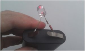
The easiest way to determine where the plus is at the LED is the batteries from the motherboard, standard size CR2032.
Its voltage is about 3 volts, which is quite enough to light the diode. Connect the LED, depending on its glow, you will determine the location of its terminals. This way you can check any diode. However, this is not very convenient.

You can assemble a simple probe for LEDs, and not only determine their polarity, but also the operating voltage.

Diagram of a homemade probe
If the LED is connected correctly, a current of the order of 5-6 milliamps will flow through it, which is safe for any LED. The voltmeter will show the voltage drop across the LED at this current. If the polarity of the LED and the probe matches, it will light up, and you will determine the pinout.
You need to know the operating voltage, since it differs depending on the type of LED and its color (red takes on less than 2 volts).
And the last method is shown in the photo below.

Turn on the Hfe mode on the tester, insert the LED into the connector for testing transistors, in the area marked as PNP, into holes E and C, with a long leg in E. This way you can check the performance of the LED and its pinout.
If the LED is made in a different form, for example, smd 5050, you can use this method simply - insert ordinary sewing needles into E and C, and touch them with the contacts of the LED.
Any lover of electronics, and even homemade products in general, needs to know how to determine the polarity of an LED and how to check them.
Be careful when choosing the elements of your circuit. At best, they will simply fail faster, and at worst, they will instantly burst into a blue flame.
These semiconductor radio components are used in various electronic circuits as display elements. As a rule, there are no problems with their installation on the board. You don't need to be a big expert in this field to solder 2 legs inserted into the corresponding holes on the "tracks". But with the polarity, which must be taken into account when working with all semiconductor devices, and not just LEDs, people without experience have difficulties. How to determine the correct polarity?
By the length of the leads
 The easiest way is if the LED is new, never used. Its conclusions are not the same - one is slightly longer. It is easy to remember the following analogy here. The words "cathode" and "short" begin with the same letter - "K".
Therefore, the other leg, the longer one, is the anode of the LED. Knowing this, it is difficult to confuse. Although some manufacturers have something else - they may be the same. It is worth considering.
By internal content
If the flask is clearly visible, then it is not at all difficult to find the "cup" (and this is the cathode).
Finding out the polarity of the LED is not all. It is necessary to install it correctly on the board. A schematic diagram of this semiconductor is shown in the figure. The apex of the instrument symbol (triangle) indicates the cathode (minus lead).
By the body
This way, not all LEDs can be checked for polarity, as it depends on the manufacturer. But some on the "rim" opposite the cathode have a small risk (notch). If you look closely, it is not difficult to notice it. Alternatively - a small point, a cut.
With battery
Also simple technique, but here it is necessary to take into account that the LEDs different types differ in breakdown voltage. In order not to damage the semiconductor (partially or completely), a limiting resistance must be connected in series in the circuit. A nominal value of 0.1 - 0.5 kOhm is sufficient.

Multimeter
By the way, it is quite possible to use and, which is already equipped with everything you need - a power source and probes. It's even better.
Polarity determination method 1 - based on the property of the LED to "light up" when current passes through it. Therefore, its anode will be where the "plus" of the multimeter battery (the socket for the probe is "+"), and the cathode, respectively, where the minus. To check for "glow", the switch of the device is set to the position "diode measurement".
Polarity determination method 2 - here the resistance of the p-n junction is measured. The multimeter switch is in the "resistance measurement" position, the limit, depending on the tester modification, in the position more than 2 kOhm. For example, 10.
Touching the LED leads with the probes is only short-term, so as not to damage the radio component. If the polarities of the p / p and the power supply coincide, then the resistance will be small (from hundreds of Ohms to several kOhms). In this case, the red probe (it is customary to insert it into the socket of the device "+") indicates the leg-anode, and the black ("-"), respectively, to the cathode.
If the multimeter shows a large resistance, then the polarity was violated when the probes touched the leads. The measurement should be repeated, changing it to make sure there is no internal break. Only in this case it is possible to speak not only about the polarity of the LED, but also about its serviceability and readiness for use as intended.
At various thematic forums there are judgments that nothing terrible will happen; you can connect the power supply in any polarity, and this will not be reflected on the LED. But it is not so.
- First, it all depends on the magnitude of the breakdown voltage, that is, the characteristics of a particular semiconductor.
- Secondly, it can continue to work, but partially lose its properties. Simply put, to shine, but not as much as it should.
- Thirdly, such experiments negatively affect the operational life of the LED. If its manufacturer's guaranteed MTBF is about 45,000 hours (on average), then after such polarity checks it will last much less. Confirmed by practice!