Description:
Such measures are the installation of automated control units for heating systems (hereinafter referred to as ACU) instead of thermal or elevator units, the installation of balancing valves on the risers of heating systems and thermostatic valves on the connections to heating devices.
Errors in the implementation of automated control units for heating systems in Moscow (2008–2009)
A. M. Filippov, Head of the Inspectorate for Energy Saving Control of the State Housing Inspectorate of Moscow
With the adoption of the Federal Law of November 23, 2009 No. 261-FZ “On energy saving and increasing energy efficiency and on introducing amendments to certain legislative acts Russian Federation» the importance of energy saving in residential buildings is increasing, especially measures that allow not only automation, but also reduction of thermal energy consumption apartment buildings, as well as optimize the distribution of heat between consumers in the house. Such measures are the installation of automated control units for heating systems (hereinafter referred to as ACU) instead of thermal or elevator units, the installation of balancing valves on the risers of heating systems and thermostatic valves on the connections to heating devices.
Prerequisites for the implementation of AMS
The concept of ACU first appeared back in 1995, when the concept “Modern energy-saving heat supply and heating systems for buildings in mass construction in Moscow” and a program for its implementation were developed and approved at MNIITEP. Subsequently, the implementation of ACM was prescribed in the new edition of MGSN 2.01–99 “Energy saving in a building”, then on April 27, 2002, a meeting of the Moscow City Architecture Complex was held, at which, among other things, they considered the issue “On standard technical solutions for equipping buildings under construction.” residential buildings automated control units for heating systems.”
In 2008, the State Unitary Enterprise MoszhilNIIproekt, together with Danfoss LLC, compiled an album “Automated control units” using technical solutions of a standard project, and in May 2008, the heat supply organization OJSC MOEK held two meetings with the participation of design and contractors on the installation of automatic control units on the design and development of technical specifications for linking a standard design for the installation of automatic control units during the overhaul of residential buildings of the 2008–2014 program.
Since August 2008, mass implementation (installation) of automatic control units began in residential buildings instead of elevator and heating units, and currently in Moscow the number of residential buildings with installed ACU reaches 1000 buildings, which is approximately 3% of the city's residential buildings.
Operating principle and advantages of using ACU
What an ACU is, its structure and principle of operation were described repeatedly in the works of M. M. Grudzinsky, S. I. Prizhizhetsky and V. L. Granovsky, including in. In addition, a similar principle of equipment operation is used in the central heating point of JSC MOEK (formerly in the heating points of the State Unitary Enterprise Mosgorteplo) in the automatic control system of a dependent heating system (SARZSO), but only for transient modes in autumn and spring.
In short, ACU is a set of devices and equipment that provide automatic control of temperature and coolant flow at the entrance to each building exactly in accordance with the temperature schedule specified for this building or in accordance with the needs of residents.
The advantage of ACU in comparison with thermal and elevator units that have a fixed cross-section of the passage opening (elevator nozzle, throttle diaphragm) through which the coolant enters the intra-house heating system is the ability to change the amount of supplied coolant depending on the water temperature in the supply and return pipelines of the system heating with correction for outside air temperature in accordance with the temperature schedule.
Unlike elevator units installed on each section of the house, the ACU is installed, as a rule, one per building (if there are 2 heat inputs in the house, then 2 ACU are installed), and the connection is made after the thermal energy metering unit of the heating system (if there is one ).
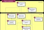
The schematic diagram and axonometric view of the ACU is shown in Fig. 1, 2 (based on materials from Danfoss LLC). Design options are possible depending on the connection diagram to the heating network, hydraulic modes at the thermal input, the specific design of the building's heating system and operating conditions (12 standard solutions in total).
Figure 2. |
An approximate diagram of the ACU provides: 1 – electronic unit (control panel); 2 – outside air temperature sensor; 3 – coolant temperature sensors in the supply and return pipelines; 4 – flow regulator valve with gear drive; 5 – differential pressure regulator valve; 6 – filter; 7 – circulation pump; 8 – check valve.
As can be seen from the diagram, the ACU fundamentally consists of three parts: network, circulation and electronic.
The network part of the ACU includes a coolant flow regulator valve with a gear drive, a differential pressure regulator valve with a spring control element and a filter.
The circulation part of the ACU includes a circulation (mixing) pump and a check valve. Two Grundfos pumps (or other types of pumps that meet the requirements of the automatic control system) are installed as mixing pumps, which operate alternately on a timer with a 6-hour cycle. The operation of the pumps is monitored by a signal from a differential pressure sensor installed on the pumps.
The electronic part of the ACU includes an electronic unit (control panel) that provides automatic control thermomechanical and pumping equipment in order to maintain a given temperature schedule and hydraulic mode in the heating system of the building, an ECL card (intended for programming the controller thermal regime), an outdoor air temperature sensor (installed on the north side of the building facade), coolant temperature sensors in the supply and return pipelines and a gear electric drive for the coolant flow control valve in the network part of the ACU.
Errors when implementing ACS
The main topic of this article is the mistakes made when planning work, designing and installing automatic control units in Moscow, which nullified all the work done and did not allow us to achieve the planned indicators for energy efficiency and energy saving. For a year and a half, the installed ACUs were practically not used for their intended purpose or were used ineffectively, expensive equipment often stood idle in a switched-off state, and the coolant entered the in-house heating systems through non-dismantled elevators.
Of course, many of the errors were later corrected, and the work of the automated control system was established, but errors could have been prevented with the correct organization of work at all stages of the process.
So what were these mistakes?
1. At the stage of planning and organizing work.
When choosing technical solution, in violation of the requirements of MGSN 2.01–99 “Energy Saving in Buildings” (clause 4.2.1.), a technical and economic comparison of the options was not carried out: 1) installation of automatic heating units from distribution networks of central heating stations or 2) installation of ITP from city main heat pipelines and water supply networks. As a result, when installing the ACU, the functions of the equipment installed in the central heating center were duplicated, which is contrary to the “Rules technical operation thermal power plants" of Rostekhnadzor of the Russian Federation (clause 9.1.2.), and the installation of automatic control units and balancing valves led to an increase in hydraulic resistance in the system and the need to replace (reconstruct) the thermal mechanical equipment of the central heating station. However, the reconstruction of the central heating substations was not envisaged, and the AMUs were not implemented in a cluster method, starting from the end buildings, but not comprehensively, only in individual buildings at the beginning or middle of the link to the central heating substation. As a result, the non-integrated installation of automatic heating units disrupted the established hydraulic and thermal balance in intra-block heating networks, led to a deterioration in the operation of the heating systems of most connected buildings and necessitated expensive thermal adjustments (with the calculation of the diameters of elevator nozzles and throttle diaphragms, their installation on input-distribution units and subsequent adjustment (replacement) during operation during the heating season.
2. At the design stage:
– there were no working designs, often instead of working designs, copies from a standard design were used without calculations, selection and linking of equipment to local conditions, which led to erroneous decisions when selecting and installing equipment and, as a consequence, to violations of heat supply conditions during its operation;
– the selected installation schemes for the ACU did not meet the required ones, which immediately had a negative impact on the heat supply. For example, in three residential buildings of the JSC, as a result of dismantling elevator unit and the use of an ACU scheme in a dependent heating system, intended for independent systems without a mixing unit, the design temperature schedule of the system operation (95–70 °C) was violated and the primary superheated coolant with a temperature schedule (150/70 °C) entered the heating devices, which led to overheating of the residential premises closest to the coolant flow and to disruption of coolant circulation in the end risers (underheating of the premises located on the end risers). Operating the system in this mode was fraught with burns to residents when touching devices and pipelines. Only timely intervention helped eliminate this error before the onset of cold weather;
– issued technical specifications(specifications) did not correspond to the actual parameters: for example, the specifications and the project indicated a schedule of 150/70 °C instead of the actual 105/70 °C, which resulted in an incorrect choice of the ACU scheme. Also, when issuing technical conditions for the AAU, it was not taken into account that during overhaul heating systems were reconstructed (schemes were changed from one-pipe to two-pipe, the diameters of distribution pipelines and risers, heating areas of heating devices, etc.), while the calculation of the ACU was carried out for the heating system before the reconstruction.
3. At the installation and commissioning stage:
– the time for installation was chosen incorrectly: ACUs were often installed already in winter period after the completion of other work, which led to complaints from residents about untimely start-up of heat, frequent heating shutdowns, and violations temperature regime;
– in vain they refused to install ACU in cases where balancing valves were installed on the risers of central heating systems during a major overhaul. Their installation led to a sharp increase in hydraulic resistance in the systems, and in the absence of automatic control units with pumping equipment and failure to replace pumps in central heating stations in such residential buildings and neighboring houses during the heating period, problems with heat supply immediately arose;
– outdoor air temperature sensors were not mounted on the north side of the building, which led to incorrect adjustment of the thermal mode due to the influence solar radiation on the sensor (its heating);
– the operation of the automatic control unit was carried out in an emergency manual mode and was not switched to automatic mode;
– documents and ECL cards were missing due to the fact that the installation company did not hand them over management company;
– there was no backup power supply to the ACU, which in the event of a power outage could lead to a shutdown of the central heating system;
– adjustment and adjustment work and noise reduction measures were not carried out;
– there was no maintenance of the automatic control unit.
As a result of these errors and violations, in houses with installed automatic control units, numerous complaints from residents arose about the heating system not warming up and noise from the operation of the equipment.
All of the above was made possible due to poor organization of work and lack of proper control on the part of the customer over all stages of the process of implementing automated control systems. The author hopes that the published article will help avoid similar mistakes in the future, both in Moscow and in other cities.
When implementing an automatic control system, it is necessary to clearly organize the work of design organizations, relevant construction, installation and repair and maintenance services, carefully check the issued technical specifications for compliance with actual data, conduct technical supervision at each stage of work and immediately after completion of installation begin maintenance of the automatic control system by a specialized organization. . Otherwise, downtime of expensive ACU equipment or its unqualified maintenance will lead to failure, loss of technical documentation and other negative consequences.
Effective use of ACU
The use of AAU is most effective in the following cases:
– in houses with subscribed elevator units of the heating system directly connected to the city main heating networks;
– in end houses connected to a central heating substation with insufficient pressure drop in the central heating system with the obligatory installation of central heating pumps;
- in houses with gas water heaters(with decentralized hot water supply) and central heating.
The ADU should be installed comprehensively, using the cluster method, covering all residential and non-residential buildings connected to the central heating point without exception.
Installation and commissioning of the heating system and ACU equipment must be carried out simultaneously.
It should be noted that, along with the installation of automatic control units, the following measures are quite effective:
– transfer of a central heating substation with a dependent connection scheme for heating systems to an independent one with the installation of a membrane in the heating point expansion tank;
– installation in a central heating substation with a dependent connection circuit of equipment for automatic control of heat supply (AVR ZSO), similar to an ACU;
– adjustment of intra-block central heating networks with the installation of design elevator nozzles and throttle diaphragms at the input and distribution nodes of buildings;
– transfer of dead-end hot water supply systems to circulation circuits.
In general, the operation of exemplary ACUs has shown that the use of ACUs in conjunction with balancing valves on the risers of the central heating system, thermostatic valves on each heating device and carrying out insulation measures allows saving up to 25–37% of thermal energy and ensuring comfortable conditions residence in each room.
Literature
1. Grudzinsky M. M., Prizhizhetsky S. I. Energy-efficient heating systems // “ABOK”. – 1999. – No. 6.
2. Granovsky V. L., Prizhizhetsky S. I. Heating system for residential buildings of mass construction and reconstruction with integrated automation of heat consumption // “ABOK”. – 2002. – No. 5.
Thanks to an automated heat supply control unit (ACU), installed in the basement of the house, residents can save from 20 to 30 percent of heat, depending on technical condition Houses. Such equipment is considered one of the most effective solutions in reducing the cost of housing and communal services.
The introduction of AMU significantly reduces the monthly payments of residents of both multi-apartment and private households. The equipment allows you to monitor fluctuations in external air temperature and controls the amount and temperature of coolant supplied to the house. To control operation in real time, the equipment is equipped with a dispatch system. The operation of this system allows you to avoid excessive supply of coolant or the so-called “overflow”, which residents often complain about with the arrival of the first warm days.
Heat suppliers are forced to supply more energy to the house than is necessary, since the equipment in boiler rooms does not allow them to quickly respond to changes in outside air temperature. To lower the temperature in their apartments, many open windows, thereby heating the street at their own expense and at the expense of their neighbors. The overflow effect is especially visible through a thermal imager, and the consequences are reflected in heating bills that are inflated by about 30 percent.
ASU is expensive equipment, but there is a mechanism that provides for its installation at the expense of the energy service company. At the same time, compensation for investors' costs for the purchase and installation of equipment is carried out at the expense of the savings obtained. The contract is concluded for a period of 3 to 5 years, depending on the volume of consumption and the amount of savings achieved. Upon expiration of the contract installed equipment is transferred free of charge to residents in good working order.
And most importantly, residents will never have to pay for excess heat at their own expense, regardless of outside temperature or its hesitation.
What you need to do to install ACU for free
- It is necessary to hold a general meeting of homeowners to conclude an agreement with representatives of the energy service company.
- The energy service company, based on the decision of the residents’ meeting, signs an agreement for the free installation of energy-saving equipment.
- The energy service company carries out work on the installation of automatic control units and related energy-saving measures.
- For the duration of the contract, the amount of payment for heating will remain the same, but savings due to rational heat consumption will be distributed between residents and the energy service company: part of the income will go to compensate the company’s costs, and part to the residents of the house.
- At the end of the contract, all savings received will remain with the residents.
We will help you understand the concepts associated with control units for heating and hot water systems, as well as the conditions and methods of using these units. After all, inaccuracy of terminology can lead to confusion in determining, for example, the permitted type of work during the overhaul of a multi-unit building.
The equipment of the control unit reduces the consumption of thermal energy to the standard level when it enters the MKD in an increased volume. A common terminology must correctly reflect the functional load that such equipment carries. There is no desired unity yet. And misunderstandings arise, for example, when replacing a unit of an outdated design with a modern automated one is called unit modernization. In this case, the outdated unit will not be improved, that is, not modernized, but simply replaced with a new one. Replacement and modernization are independent species works
Let's figure out what it is - automated control unit.
What types of control units are there for heating and water supply systems?
Control units for any type of energy or resource include equipment that directs this energy (or resource) to consumers and, if necessary, regulates its parameters. Even a collector in a house can be classified as a thermal energy control unit, receiving coolant with the parameters necessary for the heating system and directing it to various branches of this system.
In MKDs connected to a heating network with high coolant parameters (water superheated to 150 °C), elevator units and automated control units can be installed. DHW parameters can also be adjusted.
In the elevator unit, the coolant parameters (temperature and pressure) are reduced to the specified values, that is, one of the main control functions is carried out - regulation.
In an automated control unit, automation with feedback regulates the parameters of the coolant, ensuring the desired air temperature in the room, regardless of outside temperature air, and maintains the required pressure difference in the supply and return pipelines.
Automated heating system control units (AHU SO) can be of two types.
In the AUU of the first type, the coolant temperature is brought to the specified values by mixing water from the supply and return pipelines using network pumps, without installing an elevator. The process is carried out automatically using feedback from a temperature sensor installed in the room. The coolant pressure is also automatically adjusted.
Manufacturers give automated units of this type a variety of names: heat control unit, weather control unit, weather control unit, mixing unit weather control, automated mixing unit, etc.
Subtlety
The adjustment must be complete
Some enterprises produce automated units that regulate only the temperature of the coolant. The absence of a pressure regulator can cause an accident.
AUU CO of the second type includes plate heat exchangers and forms an independent heating system. Manufacturers often call them heating points. This is not true and causes confusion when placing orders.
In MKD DHW systems, liquid thermostats (TRR) can be installed, which regulate the water temperature, and automated DHW system control units that ensure the supply of water at a given temperature according to an independent circuit.
As you can see, not only automated nodes can be classified as control nodes. And the opinion that outdated elevator units and TRZ are incompatible with this concept is incorrect.
The formation of an erroneous opinion was influenced by the wording in Part 2 of Art. 166 Housing Code of the Russian Federation: “nodes for controlling and regulating the consumption of thermal energy, hot and cold water, gas." It cannot be called correct. Firstly, regulation is one of the functions of management, and this word should not have been used in the above context. Secondly, the word “consumption” can also be considered redundant: all the energy entering the node is consumed and measured by instruments. At the same time, there is no information about the target to which the control node directs thermal energy. We can say more specifically: a control unit for thermal energy spent on heating (or hot water supply).
By managing thermal energy, we ultimately control heating or hot water systems. Therefore, we will use the terms “heating system control unit” and “DHW system control unit.”
Automated nodes are new generation control nodes. They meet the most modern requirements for the subject of managing heating and hot water systems, and make it possible to raise the technological level of these systems to complete automation of the processes of regulating the parameters of the temperature regime of indoor air and water in the hot water supply, as well as automation of heat consumption metering.
Elevator units and TRZ, due to their design, cannot meet the above requirements. Therefore, we classify them as control units of the previous (old) generation.
So, let's summarize the first results. There are four types of control units for heating and hot water systems. When choosing a control unit, find out what type it is.
Can you trust the names?
Manufacturers of control units based on mixing coolant from the supply and return pipelines often call their products weather regulators. This name does not reflect their properties and purpose at all.
The automated control unit does not regulate the weather. Depending on the outside air temperature, it regulates the temperature of the coolant. This way the room maintains the desired air temperature. But automated units with heat exchangers and even elevator units do the same thing (but with less accuracy).
Therefore, let’s clarify the name: automated unit (mixing type) for controlling the heating system. Next, you can add its name assigned by the manufacturer.
Manufacturers of automated control units with heat exchangers usually call their products heat points (TS). Let's turn to the regulatory documents.
To make sure that it is incorrect to identify automated units with TP, let us turn to SNiP 41-02-2003 and their updated version - SP 124.13330.2012.
SNiP 41-02-2003 " Heating network» consider a heating point as a separate room that meets special requirements, which houses a set of equipment for connecting consumers of thermal energy to the heating network and giving this energy the specified parameters for temperature and pressure.
SP 124.13330.2012 defines a heat station as a structure with a set of equipment that allows you to change the thermal and hydraulic conditions of the coolant, provide accounting and regulation of the consumption of thermal energy and coolant. This is a good definition of a TP, to which the function of connecting equipment to the heating network should be added.
In the Rules for the Technical Operation of Thermal Power Installations (hereinafter referred to as the Rules), a TP is a set of devices located in a separate room, providing connection to the heating network, control of heat distribution modes and regulation of coolant parameters.
In all cases, the TP links together the complex of equipment and the room in which it is located.
SNiP divides heating points into free-standing, attached to buildings and built into buildings. In MKD, TPs are usually built-in.
The heating point can be group or individual - serving one building or part of a building.
Now let's formulate a correct definition.
An individual heating point (IHP) is a room in which a set of equipment is installed for connecting to the heating network and supplying consumers with an MKD or one part of it with coolant with regulation of its thermal and hydraulic conditions to give the coolant parameters a given value for temperature and pressure.
IN this definition ITP places the main importance on the room in which the equipment is located. This was done, firstly, because such a definition is more consistent with the definition presented in SNiP and SP. Secondly, it warns about the incorrectness of using the concepts ITP, TP and the like to designate automated control units for heating and hot water supply systems manufactured at various enterprises.
Let us also clarify the name of the control unit of the type under consideration: an automated unit (with heat exchangers) for controlling the heating system. Manufacturers may indicate proper name products.
How to qualify work with the control unit
Certain works are associated with the use of automated control units:
- installation of control unit;
- repair of control unit;
- replacing the control unit with a similar one;
- modernization of the control unit;
- replacement of an outdated design unit with a new generation unit.
Let us clarify what meaning is embedded in each of the listed works.
Installation of the control unit implies its absence and the need for installation in the MKD. This situation may arise, for example, when two or more houses are connected to one elevator unit (houses on a coupling) and it is necessary to install an elevator unit on each house to be able to separately account for heat energy consumption and increase responsibility for the operation of the entire heating system in each house. You can install any control unit.
Repair of the control unit of engineering systems ensures the elimination of physical wear and tear with the possibility of partial elimination of obsolescence.
Replacing the unit with a similar one that does not have physical wear assumes the same result as when repairing the unit, and can be done instead of repair.
Modernization of a unit means its renewal, improvement with the complete elimination of physical and partial obsolescence within the limits existing structure node. Both direct improvement of an existing unit and its replacement with an improved unit are all types of modernization. An example is the replacement of an elevator unit with a similar unit with an adjustable elevator nozzle.
Replacing units of an outdated design with units of a new generation involves the installation of automated control units for heating and hot water systems instead of elevator units and fuel distribution units. In this case, physical and moral wear and tear is completely eliminated.
All these are independent types of work. This conclusion is confirmed by Part 2 of Art. 166 Housing Code of the Russian Federation, where as an example independent work The installation of the thermal energy control unit is shown.
Why do you need to determine the type of work?
Why is it so important to classify this or that work related to control units as a certain type of independent work? This is of fundamental importance when performing selective overhauls. Such repairs are carried out from the capital repair fund, formed through mandatory contributions from the owners of premises to the apartment building.
The list of works on selective major repairs is given in Part 1 of Art. 166 Housing Code of the Russian Federation. The above-mentioned independent works were not included. However, in Part 2 of Art. 166 of the RF Housing Code states that a subject of the Russian Federation may supplement this list with other works by the relevant law. In this case, it becomes fundamentally important that the wording included in the list of work corresponds to the nature of the planned use of the control unit. Simply put, if a unit was to be modernized, then the list should include work with exactly the same name.
Example
St. Petersburg expanded the list of overhaul works
In the Law of St. Petersburg dated December 11, 2013 No. 690-120 “On major repairs” common property in apartment buildings in St. Petersburg" in 2016, the following independent work was included in the list of selective overhaul works: installation of control units and regulation of thermal energy, hot and cold water, electrical energy, gas.
The wording is completely borrowed from the Housing Code of the Russian Federation with all the inaccuracies that we noted earlier. At the same time, it clearly indicates the possibility of installing a control unit and regulation of thermal energy, i.e., a control unit for the heating system and hot water supply system, during selective major repairs carried out in accordance with this law.
The need to perform such independent work is due to the desire to separate houses on a coupling, i.e., houses whose heating systems receive coolant from one elevator unit, and install on each house its own heating system control unit.
The amendment made to the law of St. Petersburg allows the installation of both a simple elevator unit and any automated control unit for engineering systems. But it does not allow, for example, replacing an elevator unit with an automated control unit at the expense of the capital repair fund.
Important!
Automated mixing units, which do not include a pressure regulator, are not recommended for use in high-temperature heat supply networks. Automated DHW system control units should be installed only with heat exchangers forming a closed DHW system.
conclusions
- Control nodes include all nodes that direct energy into the heating or hot water system with the regulation of its parameters - from outdated elevators and TRZH to modern automated nodes.
- When considering proposals from manufacturers and suppliers of automated control units, it is necessary to recognize, behind the beautiful names of weather controllers and heating units, which of the following types of units the proposed product belongs to:
- automated mixing-type unit for heating system control;
- automated unit with heat exchangers for controlling a heating system or hot water supply system.
After determining the type of automated unit, you should study in detail its purpose, technical characteristics, cost of the product and installation work, operating conditions, frequency of repair and replacement of equipment, operating costs and other factors.
- When deciding to use an automated control unit for engineering systems during selective major repairs of apartment buildings, you need to make sure that the selected type of independent work for installation, repair, modernization or replacement of the control unit exactly corresponds to the name of the work included in the list of capital works by the law of the subject of the Russian Federation MKD repair. Otherwise, the selected type of work to use the control unit will not be paid for from the capital repair fund.
An automated control unit (ACU) of a heating system is a type of individual heating point, which is designed to automatically regulate coolant parameters (pressure, temperature) in a building heating system depending on the outside temperature and operating conditions.
The ACU consists of a mixing pump, an electronic temperature controller that maintains the calculated temperature curve of the coolant, a control valve and a differential pressure and flow controller. Structurally, the ACU is a block on a metal support frame on which are installed: pipeline blocks, a pump, control valves, electric drives, automation, instrumentation (pressure gauges, thermometers), filters, and mud collectors.
The operating principle of the ACU is as follows: provided that the temperature of the coolant in the direct pipeline of the heating network exceeds the required one (according to the temperature chart), electronic regulator includes a mixing pump, which adds coolant to the heating system from the return pipeline (i.e. after the heating system), maintaining the required temperature, preventing “overheating” in the building. At this time, the hydraulic regulator closes, thereby reducing the supply of network water.
Reducing the air temperature in buildings at night does not worsen the conditions of sanitary and hygienic requirements, which in turn reduces the consumption of thermal energy and leads to its savings. Possible savings in thermal energy when automatic regulation up to 25% of annual consumption.
Rice. 1. Schematic diagram of an automated heating control unit.
Now let's do a little calculation of the effect of introducing an automated control unit in an office building.
In our example, it is planned to modernize the heating system by installing an automatic control system in accordance with current standards and regulations.
Calculation of thermal energy savings when implementing ACU
Thermal energy savings (ΔQ) when installing ACU are determined by the expression:
ΔQ= ΔQ p +ΔQ n +ΔQ with +ΔQ and, (1)
ΔQ p - thermal energy savings from eliminating overheating of buildings in the autumn-spring period, %;
ΔQ n - saving thermal energy from reducing its supply at night, %;
ΔQ с - savings of thermal energy from reducing its supply on weekends, %;
ΔQ and - thermal energy savings by taking into account heat input from solar radiation and household heat release, %.
Saving thermal energy ΔQп from eliminating the overheating of buildings in the autumn-spring period of the heating season, when the heat source, to meet the needs of hot water supply, releases coolant with a constant temperature exceeding the required temperature for closed systems heating (see Fig. 2. Temperature chart 130-70) can be approximately determined from table No. 1.

Rice. 2. Temperature chart 130-70.
Table No. 1.
The relative duration of the autumn-spring period, for different regions(with different design temperatures of outside air during the heating period), necessary to determine AQ p, can be found from table. No. 2.
Table No. 2. Relative duration of the autumn-spring period at different calculated outside air temperatures during the heating period.

Saving heat energy AQ n from reducing its supply at night is determined by the expression:
![]()
where a is the duration of the decrease in heat supply at night, h/day;
Δt nр in - reduction in indoor air temperature during non-working hours, °C;
t Р в - average calculated air temperature in the premises, °C. Selected according to SNiP 2.04.05-86 "Heating, ventilation and air conditioning. Design standards."
t avg - average outside air temperature for the heating season, °C. Selected according to SNiP 2.04.05-86.
For residential buildings: It is recommended to reduce the heat output from 21:00. A hours, the regulator should turn on the heating at a heat flow rate that ensures the temperature is restored to normal. Normal temperature should be achieved by 6-7 am. The most appropriate temperature reduction = 2 °C (from = 20 °C to 18 °C). For approximate calculations can be accepted A= 6-7 hours
For administrative buildings: duration of reduction in heat supply A is determined by the operating mode of the building, for approximate calculations you can take A= 8-9 hours. The most appropriate amount of temperature reduction AC= 2-4 °C. With a deeper decrease in temperature, it is necessary to take into account the ability of the heat source to quickly increase heat output when the outside air temperature sharply decreases. In any case, the temperature value during the period of night-time decrease in heat consumption in public buildings should ensure that there is no condensation on the walls at night.
Saving heat energy ΔQс from reducing its supply on weekends is determined by expression (3):
![]()
Where b- duration of reduction in heat supply on non-working days, days/week.
(with a 5-day work week b= 2, at 6 days b = 1).
The amount of reduction in indoor air temperature during non-working hours is selected in accordance with the recommendations for formula (2).
Saving heat energy ΔQ and due to taking into account heat input from solar radiation and household heat release is determined by expression (4):
![]()
where Δt and in - averaged over the heating season, the excess of indoor air temperature above comfortable due to heat gain from solar radiation and household heat release, °C. Approximately, you can take Δt and = 1-1.5 °C (according to experimental data).
Calculation example:
Office building in Moscow. Opening hours: 5 days a week, from 9:00 to 18:00.
t R in = 18 °C, t avg = -3.1 °C, t R n = -28 °C (according to SNiP 2.04.05-86). It is assumed that the indoor air temperature will decrease by Δtнр в = 3 °С at night (A= 8 hours/day) and weekends (b= 2 days/week). In this case:
Table No. 3. Calculation of the economic effect from the introduction of automated control systems.
|
Options |
Designation |
Unit measurements |
Meaning |
|
|
Saving thermal energy by installing ACU |
ΔQ=ΔQ n +ΔQ with +ΔQ and |
|||
|
Duration of reduction in heat supply at night |
||||
|
Duration of reduction in heat supply on non-working days |
||||
|
Reducing indoor air temperature during non-working hours |
||||
|
Average calculated indoor air temperature |
Determined according to SNiP 2.04.05-91* "Heating, ventilation and air conditioning" |
|||
|
Average outdoor temperature for the heating season |
Determined according to SNiP 23-01-99 "Building climatology" |
|||
|
Averaged over the heating season, the excess of indoor air temperature above the comfortable temperature due to heat gain from solar radiation and household heat release |
||||
|
Saving thermal energy from eliminating overheating of buildings during the autumn-spring heating season |
ΔQP |
|||
|
Saving heat energy by reducing its supply at night |
ΔQн=((a·Δtррв)/(24·(tрв-tррн))*100 | |||
|
Saving heat energy by reducing its supply on weekends |
ΔQн=((b·Δtррв)/(24·(tрв-tррв))*100 | |||
|
Saving heat energy by taking into account heat gains from solar radiation and household heat emissions |
ΔQн=(Δtв)/(tрв-tрр)*100 |
Thus, the thermal energy savings from installing an ACU will amount to 11.96% of the annual heat consumption for heating.
Annex 1
at the disposal of the Department
and improvement of the city of Moscow
REGULATIONS
PERFORMANCE OF MAINTENANCE AND REPAIR WORKS
AUTOMATED CONTROL UNITS (AUU) OF THE CENTRAL
HEATING HOUSES IN MOSCOW
1. Terms and definitions
1.1. GU IS districts - State institutions of the city of Moscow, district engineering services - organizations created through reorganization government agencies of the city of Moscow, unified information and settlement centers of the administrative districts of the city of Moscow in accordance with the Decree of the Government of Moscow dated January 1, 2001 N 299-PP "On measures to bring the management system of apartment buildings in the city of Moscow in accordance with the Housing Code of the Russian Federation" and performing the functions, imposed on them by the said resolution and other legal acts of the city of Moscow. Unified information and settlement centers of Moscow districts operate as part of the State Information System of Moscow districts.
1.2. Managing organization - legal entity
any organizational and legal form, including HOA, housing cooperative, residential complex or other specialized consumer cooperative, providing services and performing work for the proper maintenance and repair of common property in such a house, providing utilities to the owners of premises in such a house and using the premises in this house persons carrying out other activities aimed at achieving the goals of managing an apartment building and performing the functions of managing an apartment building on the basis of a management agreement.
1.3. Automated control unit (AUU) is a complex thermal device designed to automatically maintain optimal parameters coolant in the heating system. An automated control unit is installed between the thermal system and the heating system.
1.4. Verification of ACS components is a set of operations performed by specialized organizations in order to determine and confirm compliance of ACS components with established technical requirements.
1.5. Maintenance of the automatic control unit is a set of works to maintain the automatic control unit in good condition, prevent failures and malfunctions of its components and ensure the specified performance qualities.
1.6. Serviced house - a residential building in which maintenance and Maintenance AUU.
1.7. A service log is an accounting document that records data on the condition of the equipment, events and other information related to the maintenance and repair of the automated control unit of the heating system.
1.8. Repair of automatic control unit - current repair of automatic control unit, including: replacement of gaskets, replacement/cleaning of filters, replacement/repair of temperature sensors, replacement/repair of pressure gauges.
1.9. Container for draining the coolant - a water capacity of at least 100 liters.
1.10. ETKS - Unified Tariff qualification directory works and professions of workers, consists of tariff and qualification characteristics containing characteristics of the main types of work by profession of workers, depending on their complexity and the corresponding tariff categories, as well as the requirements for the professional knowledge and skills of workers.
1.11. EKS - Unified qualification directory of positions of managers, specialists and employees, consists of qualification characteristics of positions of managers, specialists and employees, containing job responsibilities and requirements for the level of knowledge and qualifications of managers, specialists and employees.
2. General provisions
2.1. These Regulations determine the scope and content of work performed by specialized organizations for maintenance automated control units (ACU) for heat supply in residential buildings in Moscow. The Regulations contain the basic organizational, technical and technological requirements when performing maintenance work on automated thermal energy control units installed in central heating systems of residential buildings.
2.2. This regulation has been developed in accordance with:
2.2.1. Law of the city of Moscow No. 35 of July 5, 2006 “On energy saving in the city of Moscow.”
2.2.2. Decree of the Moscow Government dated January 1, 2001 N 138 “On approval of Moscow city building standards “Energy saving in buildings. Standards for thermal protection and heat and water power supply."
2.2.3. Decree of the Moscow Government dated January 1, 2001 N 92-PP "On approval of Moscow City Building Standards (MGSN) 6.02-03 "Thermal insulation of pipelines for various purposes."
2.2.4. Decree of the Moscow Government dated January 1, 2001 N 299-PP “On measures to bring the management system of apartment buildings in the city of Moscow into compliance with the Housing Code of the Russian Federation.”
2.2.5. Decree of the Government of the Russian Federation dated January 1, 2001 N 307 “On the procedure for providing utilities citizens."
2.2.6. Resolution of the Gosstroy of Russia dated January 1, 2001 N 170 “On approval of the Rules and Standards for the technical operation of the housing stock.”
2.2.7. GOST R 8. "Metrological support of measuring systems."
2.2.8. GOST 12.0.004-90 "System of labor safety standards. Organization of labor safety training. General provisions."
2.2.9. Intersectoral rules on labor protection (safety rules) for the operation of electrical installations, approved by Decree of the Ministry of Labor of the Russian Federation dated 01.01.2001 N 3, order of the Ministry of Energy of the Russian Federation dated 01.01.2001 N 163 (with amendments and additions).
2.2.10. Rules for the design of electrical installations approved by the Main Technical Directorate, Gosenergonadzor of the USSR Ministry of Energy (with amendments and additions).
2.2.11. Rules for the technical operation of consumer electrical installations, approved by Order of the Ministry of Energy of the Russian Federation dated January 1, 2001 N 6.
2.2.12. A passport for the automated control unit (ACU) of the manufacturer.
2.2.13. Instructions for installation, start-up, regulation and operation of an automated control unit for heating systems (ACU).
2.3. The provisions of these Regulations are intended for use by organizations carrying out maintenance and repair of automated control units of the central heating system of residential buildings in the city of Moscow, regardless of the form of ownership, legal form and departmental affiliation.
2.4. This Regulation establishes the procedure, composition and timing of maintenance work for automated control units of heating systems (ACU) installed in residential buildings.
2.5. Work on maintenance and repair of automated heating system control units (AHU) installed in residential buildings is carried out on the basis of a maintenance agreement concluded between a representative of the owners of a residential building (management organization, including HOA, housing cooperative, residential complex or an authorized owner-representative in case of direct control).
3. Maintenance log
and repair of automatic control unit (Service log)
3.1. All operations performed during the performance of maintenance and repair work on the automatic control unit are subject to entry into the journal for the execution of maintenance and repair work on the automatic control unit (hereinafter referred to as the Service Log). All sheets of the journal must be numbered and certified with the seal of the Managing Organization.
3.2. Maintenance and storage of the Service Log is carried out by the Management Organization, which manages the Serviced House.
3.3. Personal responsibility for the safety of the journal rests with a person authorized by the Managing Organization.
3.4. The following data is entered into the Service Log:
3.4.1. The date and time the maintenance work was performed, including the time the maintenance team gained access to the technical room of the house and the time it was completed (time of arrival and departure).
3.4.2. Composition of the service team performing technical maintenance of the automatic control unit.
3.4.3. List of works performed during maintenance and repair, time of completion of each of them.
3.4.4. Date and number of the contract for the performance of maintenance and repair work on the automatic control unit.
3.4.5. Service organization.
3.4.6. Information about the representative of the Management Organization who accepted the maintenance work for the ACU.
3.5. The service log refers to the technical documentation of the Serviced House and is subject to transfer in the event of a change in the Management Organization.
and repair of automatic control units
4.1. Maintenance and repair of the automatic control unit is carried out by qualified workers in accordance with the frequency established by Appendix 1 to these Regulations for the performance of work.
4.2. Work on the maintenance and repair of automatic control units is carried out by specialists whose specialty and qualifications meet the minimum established requirements of clause 5 of these Technological maps.
4.3. Repairs must be carried out at the installation site of the ACU or at the enterprise directly carrying out the repairs.
4.4. Preparation and organization of work on maintenance and repair of automatic control units.
4.4.1. The management organization agrees with the organization planned to be engaged to carry out technical maintenance of the automatic control unit, a work schedule, which may be an appendix to the technical maintenance agreement for the automatic control unit.
4.4.2. The name and composition of the maintenance team is communicated to the Managing Organization in advance (before the day of the maintenance and repair of the automatic control unit). Residents of the Serviced House must be notified in advance of the work being carried out. Such notification may be made in the form of a notice visible to the residents of the building. The responsibility for notifying residents rests with the Management Organization.
4.4.3. The Managing Organization provides the following documents (copies) for review by the Service Organization:
Certificate;
Technical certificate;
Installation instructions;
Start-up and commissioning instructions;
User manual;
Repair instructions;
Warranty certificate;
Factory test certificate of the automatic control unit.
4.5. Access for the technical operation team to the technical room of the Serviced House.
4.5.1. Access to the technical premises of a residential building for carrying out maintenance and repair work on the ACU is carried out in the presence of a representative of the Management Organization. Information about the time of access of the maintenance team to the technical room of the Serviced House is entered into the Service Log.
4.5.2. Before starting work, the readings of the control and measuring devices of the control unit are entered into the Service Log, indicating the identifier of the control and measuring device, its readings and the time they were recorded.
4.6. Maintenance and repair work for automatic control units.
4.6.1. An employee of the maintenance team of the Service Organization performs an external inspection of the ACU units for the absence of leaks, damage, extraneous noise, and contamination.
4.6.2. After the inspection, an inspection protocol is drawn up in the Service Log, which records information about the condition of the connecting pipes, their connection points, and ACU units.
4.6.3. If there are leaks at pipe connections, it is necessary to identify the cause of their occurrence and eliminate them.
4.6.4. Before inspecting and cleaning the ACU elements from contaminants, it is necessary to turn off the power supply to the ACU.
4.6.5. First, turn off the pumps by turning the pump control switches on the front panel of the control panel to the off position. After this, you should open the control panel and switch the automatic circuit preparation machines for pumps 3Q4, 3Q14 to the off position according to diagram 1 (not shown) (Appendix 2). Then the control controller should be de-energized; to do this, it is necessary to move the single-pole switch 2F10 to the off position according to diagram 1.
4.6.6. After completing the above steps, the three-pole switch 2S3 should be switched to the off position according to diagram 1. In this case, the phase indicators L1, L2, L3 on the external panel of the control panel should go out.
4.7. Checking the operation of emergency protection and alarms, servicing electrical equipment.
4.7.1. Turn off the circuit breaker in the control panel of the running pump according to electrical diagram ACU control panel.
4.7.2. The pump should stop (the control panel on the pump will go out).
4.7.3. The green pump operation light on the control panel should go out, and the red pump failure light will light up. The controller display will begin to flash.
4.7.4. The backup pump should automatically start working (the control panel on the pump will light up, the green light on the control panel will light up for the backup pump).
4.7.5. Wait 1 min. - the backup pump must remain in operation.
4.7.6. Press any button on the controller to reset the flashing.
4.7.7. The L66 card of the ECL 301 controller is yellow side facing out.
4.7.8. Use the up button to go to line A.
4.7.9. Press the circuit I/II selection button twice, the left LED under the card should go out.
4.7.10. The controller display will show the alarm log and the ON value. There should be a number 1 in the lower left corner.
4.7.11. Press the minus button on the controller, the display should change to OFF, a double dash should appear in the lower left corner - the alarm is cleared.
4.7.12. Press the circuit selection button I/II once, the left LED under the card will light up.
4.7.13. Use the down button to return to line B.
4.7.14. Examination protective function electric drive AMV 23, AMV 413.
4.7.15. Turn off the controller power supply according to the electrical diagram of the ACU control panel.
4.7.16. The controller should turn off (the display will go dark). The electric drive must close the control valve: check this using the electric drive position indicator; it must be in the closed position (see the manufacturer's instructions for the electric drive).
4.8. Checking the functionality of heating point automation equipment.
4.8.1. Switch the ECL 301 controller to manual mode according to the manufacturer's instructions.
4.8.2. In manual mode from the controller, turn on and off the circulation pumps (monitor by the indication on the control panel and the control panel on the pumps).
4.8.3. In manual mode, open and close the control valve (monitor using the electric drive movement indicator).
4.8.4. Switch the controller back to automatic mode.
4.8.5. Check emergency switching of pumps.
4.8.6. Check the temperature readings on the controller display with the readings of indicating thermometers at the locations where the temperature sensors are installed. The difference should not be more than 2C.
4.8.7. In the controller line on the yellow side of the card, press and hold the shift button, the controller display will show the feed and processing temperature settings. Remember these values.
4.8.8. Release the shift button, the display will show the actual temperature values, the deviation from the settings should be no more than 2C.
4.8.9. Check the pressure maintained by the pressure regulator (the differential pressure maintained by the differential pressure regulator), the setting set when setting up the ACU.
4.8.10. Use the adjusting nut of the AFA pressure regulator to compress the spring (in the case of the AVA regulator, release the spring) and reduce the pressure value to the regulator (monitor using the pressure gauge).
4.8.11. Return the AFA (AVA) regulator setting to the operating position.
4.8.12. Using the adjusting nut of the AFP-9 differential pressure regulator (AVP adjusting handle), by releasing the spring, reduce the value of the differential pressure (monitor using pressure gauges).
4.8.13. Return the differential pressure regulator setting to its previous position.
4.9. Functionality check shut-off valves.
4.9.1. Open/turn the stop valve until it stops.
4.9.2. Evaluate the ease of movement.
4.9.3. Using the readings of the nearest pressure gauge, evaluate the shut-off valve's closing capacity.
4.9.4. If the pressure in the system does not decrease or does not decrease completely, it is necessary to establish the reasons for the valve leakage and, if necessary, replace it.
4.10. Cleaning mesh filter.
4.10.1. Before starting work on cleaning the strainer, it is necessary to close valves 31, 32 according to diagram 2 (not shown), located in front of the pumps. Then you should turn off valve 20 according to diagram 2, located in front of the filter.
4.10.5. After installing the filter cover, it is necessary to open valves 31, 32 according to diagram 2, located in front of the pumps.
4.11. Cleaning the impulse tubes of the differential pressure regulator.
4.11.1. Before cleaning the tubes of the differential pressure regulator, it is necessary to close valves 2 and 3 according to diagram 2.
4.11.3. To rinse the first impulse tube, you need to open tap 2 and wash it with a stream of water.
4.11.4. The resulting water should be collected in a special container (coolant drain container).
4.11.5. After flushing the first impulse tube, replace it and tighten it union nut.
4.11.6. To flush the second impulse tube, unscrew the union nut securing the second impulse tube, and then disconnect the tube.
4.11.7. To flush the second impulse tube, use tap 3.
4.11.8. After flushing the second impulse tube, reattach the tube and tighten the union nut.
4.11.9. After cleaning the impulse tubes, taps 2 and 3 should be opened according to diagram 2.
4.11.10. After opening taps 2 and 3 (diagram 2), it is necessary to bleed air from the tubes using the union nuts of the differential pressure regulator. To do this, unscrew the union nut 1-2 turns and tighten it after the air comes out of the impulse tube, tighten it. Repeat the operation for each of the impulse tubes in turn.
4.12. Cleaning the impulse tubes of the differential pressure switch.
4.12.1. Before cleaning the tubes of the differential pressure regulator, it is necessary to close valves 22 and 23 according to diagram 2.
4.12.3. To rinse the first impulse tube, you need to open tap 22 according to diagram 2 and wash it with a stream of water.
4.12.4. After flushing the first impulse tube, replace it and tighten the union nut.
4.12.5. To flush the second impulse tube, unscrew the union nut securing the second impulse tube of the differential pressure switch, and then disconnect the tube.
4.12.6. To flush the second impulse tube, use tap 23.
4.12.7. After flushing the second impulse tube, reattach the tube and tighten the union nut.
4.12.8. After cleaning the impulse tubes, taps 22 and 23 should be opened according to scheme 2.
4.12.9. After opening valves 22 and 23 (diagram 2), it is necessary to bleed air from the tubes using the union nuts of the differential pressure regulator. To do this, unscrew the union nut 1-2 turns and tighten it after the air comes out of the impulse tube, tighten it. Repeat the operation for each of the impulse tubes in turn.
4.13. Checking pressure gauges.
4.13.1. For carrying out work on calibrating pressure gauges. Before removing them, it is necessary to close valves 2 and 3 according to diagram 2.
4.13.2. Plugs are inserted into the places where the pressure gauges are attached.
4.13.3. Verification tests of pressure gauges are carried out in accordance with GOST 2405-88 and the Verification Methodology. "Pressure gauges, vacuum gauges, pressure and vacuum gauges, pressure gauges, draft gauges and pressure gauges" MI 2124-90.
4.13.4. Verification is carried out by specialized organizations whose metrological services are accredited by the Federal Agency for Technical Regulation and Metrology, on the basis of an agreement with the Managing Organization or the Service Provider.
4.13.5. Verified pressure gauges are installed in place.
4.13.6. After installing the pressure gauges, it is necessary to open valves 31 and 32 according to diagram 2.
4.13.7. The connections between pressure gauges and connecting pipes of the ACU system must be checked for leaks. The check is carried out visually within 1 minute.
4.13.8. After this, you should check the readings of all pressure gauges and record them in the Service Log.
4.14. Checking thermometer sensors.
4.14.1. A portable reference thermometer and an ohmmeter are used to test thermometer sensors.
4.14.2. An ohmmeter is used to measure the resistance between the conductors of the temperature sensor being tested. The ohmmeter readings and the time they were taken are recorded. At the point where the temperature is taken by the corresponding sensor, the temperature readings are determined using a reference thermometer. The obtained resistance values are compared with the calculated resistance value for a given sensor and for the temperature determined by a reference thermometer.
4.14.3. If the temperature sensor readings do not correspond to the required values, the sensor must be replaced.
4.15. Checking the functionality of indicator lamps.
4.15.1. It is necessary to turn on the three-pole switch 2S3 according to diagram 1 (Appendix 2).
4.15.2. The phase indicator lamps L1, L2, L3 on the front panel of the control panel should light up.
4.15.4. Then press the "Lamp Test" button on the front panel of the control panel. The “pump 1” and “pump 2” and “pump failure” lamps should light up.
4.15.5. After this, you should apply voltage to the 2F10 controller according to diagram 1, then turn on the 3Q4 and 3Q13 circuit breakers (diagram 1).
4.15.6. Upon completion of checking the condition of the lamps, a record of this is recorded in the Service Log.
5. Procedure for performing technical work
maintenance and repair of automatic control units
5.1. Preparation and organization of work on maintenance and repair of automatic control units.
5.1.1. Development and coordination with the management organization of a work schedule.
5.1.2. Access for the technical operation team to the technical room of the Serviced House.
5.1.3. Carrying out maintenance and repair work on automatic control units.
5.1.4. Handover and acceptance of work on maintenance and repair of the automatic control unit to a representative of the Managing Organization.
5.1.5. Termination of access to the technical room of the Serviced House.
6. Repair of automatic control unit
6.1. Repair of the ACU is carried out within the time limits agreed upon between the Management and Servicing organizations.
6.2. Work on the repair of the automatic control unit must be carried out by an energy engineer and a 6th category plumber, depending on the type of repair work.
6.3. A utility vehicle (Gazelle type) is used to deliver workers, equipment and materials to the work site and back, to deliver a faulty automatic control unit to a repair facility and back to the installation site.
6.4. During the repair, units from the reserve fund are installed in place of the repaired ACU units.
6.5. When dismantling a faulty ACU unit, the report records the readings at the time of dismantling, the number of the ACU unit and the reason for dismantling.
6.6. Work on repairs and preparation for verification of the automatic control unit is carried out by repair personnel of a specialized organization servicing this automatic control unit.
6.7. If one of the ACU elements fails, they are replaced with similar ones from the reserve fund.
7. Occupational safety
7.1.1. This Instruction defines the basic requirements for labor protection when performing maintenance and repair work on automatic control units.
7.1.2. Persons who have reached the age of 18, who have passed a medical examination, theoretical and practical training, a knowledge test by a qualification commission with the assignment of an electrical safety group of at least III, and who have received a certificate for permission to work independently are allowed to carry out the maintenance and repair of automated control units.
7.1.3. A mechanic may be exposed to the following health hazards: electric shock; poisoning by toxic vapors and gases; thermal burns.
7.1.4. Periodic testing of a mechanic's knowledge is carried out at least once a year.
7.1.5. The employee is provided with special clothing and safety footwear in accordance with current standards.
7.1.6. When working with electrical equipment, the worker must be provided with basic and additional protective equipment to ensure the safety of his work (dielectric gloves, dielectric mat, tools with insulating handles, portable grounding, posters, etc.).
7.1.7. The employee must be able to use fire extinguishing equipment and know their location.
7.1.8. The safe operation of automation devices located in fire and explosion hazardous areas must be ensured by the presence of appropriate protection systems.
8. Final provisions
8.1. When making changes or additions to regulations and legal acts, building codes and rules, national and interstate standards or technical documentation governing the operating conditions of the ACU, appropriate changes or additions are made to these Regulations.
Annex 1
to the Regulations
FREQUENCY OF WORK TO IMPLEMENT INDIVIDUAL TECHNICAL WORKS
OPERATIONS, USE OF MACHINES AND MECHANISMS
Name of work on | Qty | Qualification |
|
Inspection of ACU units |
|||
Turning off the power supply to the ACU | Energy Engineer |
||
Inspection of pumping equipment, instrumentation, | Energy Engineer |
||
Checking incoming and supported | Energy Engineer |
||
Checking emergency protection and alarms, maintenance |
|||
Failover Test | Energy Engineer |
||
Checking the protective function of the electric drive | Energy Engineer |
||
Checking the indicator lamps on the panel | Energy Engineer |
||
Checking the functionality of heating point automation equipment |
|||
Checking the ECL 301 controller | Energy Engineer |
||
Checking the electric drive | Energy Engineer |
||
Checking the differential pressure switch | Energy Engineer |
||
Checking temperature sensors | Energy Engineer |
||
Checking direct acting regulators | Energy Engineer |
||
Checking the circulation pump | Energy Engineer |
||
Checking the functionality of shut-off valves |
|||
Checking ease of movement | Plumber |
||
Checking for leaks | Plumber |
||
Washing/replacing filters, pressure switch impulse tubes |
|||
Washing/replacing the strainer | Plumber |
||
Flushing/replacing impulse tubes | Plumber |
||
Bleeding the differential air regulator | Plumber |
||
Flushing/replacing relay impulse tubes | Plumber |
||
Bleeding air from the differential relay | Plumber |
||
Verification/verification of instrumentation |
|||
Removing and installing pressure gauges | Plumber |
||
Checking pressure gauges | Energy Engineer |
||
Checking temperature sensors | Energy Engineer |
||
Setting up ACU parameters |
|||
Activating ACU sensor readings | Energy Engineer |
||
Analysis of ACU sensor readings | Energy Engineer |
||
Adjusting ACU parameters | Energy Engineer |
||
Use of machines and mechanisms |
|||
Appendix 2
to the Regulations
EXTERNAL AND INTERNAL VIEW OF THE CONTROL PANEL
HARDWARE SPECIFICATION
The figure is not shown.
Appendix 3
to the Regulations
HYDRAULIC DIAGRAM OF THE AUTOMATED CONTROL UNIT
CENTRAL HEATING SYSTEMS OF A RESIDENTIAL HOUSE (AHU)
The figure is not shown.
Appendix 4
to the Regulations
TYPICAL SPECIFICATION OF AN AUTOMATED CONTROL UNIT
CENTRAL HEATING SYSTEMS OF A RESIDENTIAL HOUSE
Name | Diameter, mm | ||||
Booster pump | |||||
Control valve for | According to the project | According to the project | |||
Electric drive | AMV25, AMV55 | ||||
Magnetic filter | According to the project | According to the project | |||
Pressure regulator "up to | According to the project | According to the project | AVA, VFG-2 with | ||
Impulse tube | |||||
Ball valve with | According to the project | According to the project | |||
Steel ball valve | According to the project | According to the project | |||
Cast iron check valve | According to the project | According to the project | |||
Flexible rubber insert | According to the project | According to the project | |||
Control rods for | According to the project | According to the project | |||
Pressure gauge Ru = 16 kgf/sq. | |||||
Thermometer 0-100 °C | |||||
Ball valve with | |||||
Ball valve PN = 40, | According to the project | According to the project | |||
Ball valve PN = 40, | According to the project | According to the project | |||
ECL301 controller | |||||
temperature sensor | |||||
temperature sensor | |||||
Sleeve for ESMU sensor | |||||
Differential pressure switch | |||||
Damper tube for | |||||
Ball valve with |