Having a milling machine really simplifies the work of inserting hinges, forming complex holes, recesses, wood carving, etc. But this does not mean at all that it is necessary to have professional and expensive equipment: it is enough to have a simple manual device.
The only thing you need is to be able to basicly handle wood and use power tools. In addition, you need to have a desire, otherwise without this there will never be a result. Those who have no desire to work simply buy furniture or hire craftsmen to, for example, install new door and cut the locks. Any work, especially with power tools, requires certain knowledge, and especially safety precautions.

The milling device is designed for processing both wood and metal. With its help, it is possible to form recesses or holes of any configuration. This greatly simplifies tasks such as inserting hinges and inserting locks. Doing this with a chisel and an electric drill is not so easy, and it takes a lot of time.
There are stationary milling devices and portable (manual). Hand-held electric milling machines are considered universal devices, with the help of which, in the presence of attachments, it is possible to perform operations for various purposes; you just need to change the position of the part in relation to the device or vice versa.
Stationary devices are used in factories or factories where mass production of wood or metal products is established. Under such conditions, the cutting attachment is stationary, and the workpiece moves along the desired path. Using hand tools on the contrary, the part is fixed motionless and only then it is processed, although there are parts that require fixing a hand tool. This is provided for in the design, therefore, it is considered more universal. This is especially true when you need to process a large number of parts, but using a stationary machine is not possible.
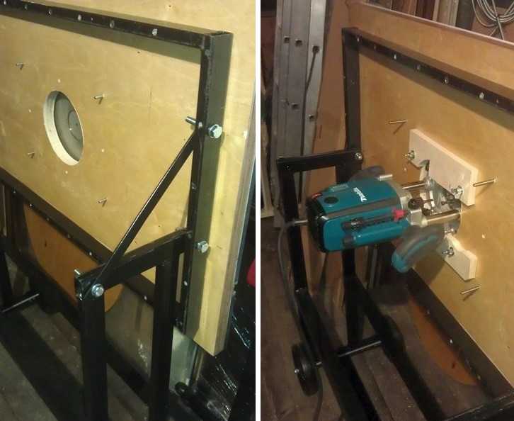 Homemade milling machine– a horizontal platform with a hole in the center, to which a hand-held device is attached from below.
 There are many types of milling machines, but for use at home or for starting your own business, universal models are more suitable. As a rule, they are equipped with a set of cutters and various devices for performing various types of operations. The only thing that is available hand router simple operations can take much longer than using a stationary machine.
Using a manual milling device it is possible to:
- Make grooves or recesses of any shape (curly, rectangular, combined).
- Drill through and non-through holes.
- Process ends and edges of any configuration.
- Cut out complex shaped parts.
- Apply drawings or patterns to the surface of parts.
- Copy parts if necessary.
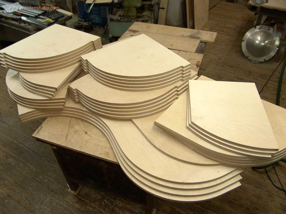 Copying parts is one of the functions of any electric milling machine.
 The presence of such functions makes it possible to simplify the production of the same type of furniture or the production of identical parts not related to furniture production. This is one of the main advantages of this tool. As a rule, to produce similar parts it is necessary to install copying machines, which are designed to perform only one operation, which is not always profitable, especially in small businesses.
Getting started and caring for the tool
To understand how it works this device, you should familiarize yourself with its main parts and their purpose.
Composition and purpose of main components
A manual milling device consists of a metal body and a motor, which is located in the same body. A shaft protrudes from the housing, onto which various collets are placed, serving as adapters. They allow you to install cutters of various sizes. The cutter is inserted directly into the collet, which is secured with a special bolt or button, which is provided on some models.
 Basic elements of manual milling device and their purpose.
 The design of the milling device includes a metal platform, which has a rigid connection to the body. It is attached to the body by means of two rods. WITH outside the stove has smooth coating, ensuring smooth movement during operation.
The manual milling device has some characteristics that can be adjusted:
- Due to the handle and scale for adjusting the milling depth. Adjustment is carried out in 1/10 mm increments.
- By adjusting the rotation speed of the cutter.
On initial stages When mastering the tool, it is better to try working at low or medium speeds. Although you should always remember that the higher the speed, the better the work. Especially if this concerns critical, visible areas that cannot be masked.
In addition to these levers, there is also a button to turn the product on and off, as well as a lock button. These elements are considered basic, ensuring high-quality and safe performance of work. There is also a parallel stop, which contributes to ease of use. It can be rigidly fixed or with the ability to adjust the shift of the working area away from the center.
Caring for a hand-held milling device

Usually, a factory product falls into the hands of a person tested and lubricated, so no additional measures should be taken. Only during its operation you need to monitor its cleanliness and serviceability. At the same time, it should be regularly cleaned of dust and the lubricant should be changed, if so written in the passport. Lubrication is especially necessary for moving parts. As an option, you can use aerosol lubricants, but you can also get by with regular ones, such as Litol. The use of thick lubricants is not recommended, as chips and dust stick to them. If aerosol lubricants are used, then this factor can be eliminated.
The sole, the smooth part of the body, also requires lubrication. Regular lubrication will ensure smooth movement.
Despite this, the purchased item should definitely be checked for quality of assembly and presence of lubricant.
Unfortunately, not all manufacturers, especially domestic ones, care about build quality. There are cases when, after the very first hours of operation, screws or screws are unscrewed from a product because they were not tightened properly.
Rotation speed adjustment
The operation of any tool is associated with certain conditions related, first of all, to the nature of the material being processed. It can be plywood, composite material or regular wood. Depending on this, the rotation speed on the electrical appliance is set. As a rule, in technical passport The operating parameters of the device are always indicated, depending on the technical characteristics and characteristics of the surfaces being processed, as well as the cutters used.
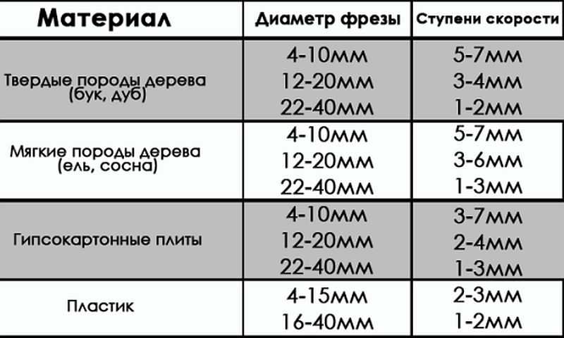 Indicators of processing speeds when using various cutters.
 Fixing the cutter
The first thing the work begins with is installing and securing the cutter. At the same time, you should adhere to the basic rule - all work is performed with the cord plug removed from the socket.
The cutter is installed according to certain marks, and if they are missing, then to a depth of no less than * the length of the cutter itself. How to install a cutter on a specific model can be found in the instructions, which must be included in the technical documents for the device. The fact is that each model can have its own design features and it is not possible to talk about this in the article.
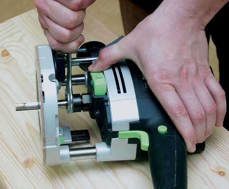 Installing the cutter on the device before starting work.
 There are both simple and more “advanced” models, as they say. Some models have a shaft rotation lock button, which makes installing the cutter easier. Some, especially expensive models, are equipped with ratchets. So it won’t be possible to specifically describe the process of installing the cutter, and it doesn’t make sense, since everyone who is familiar with the operation of such devices will figure it out in a moment.
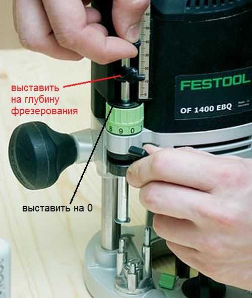
Milling depth adjustment
Each model has its own maximum milling depth. At the same time, it is not always necessary maximum depth, but a certain depth that is set before work. Even if maximum depth is required, in order not to overload the device, the milling process is divided into several stages, changing the milling depth in steps. For adjustment, special stops are provided - limiters. Structurally, they are made in the form of a disk located under the bar, on which stops of various lengths are fixed. The number of such legs can be from three to seven, and this does not mean that the more there are, the better. It is better if it is possible to adjust each of the legs, even if their number is minimal. To secure this stop in the optimal position, you should use a lock in the form of a flag.
The process for adjusting the milling depth is as follows:

 Thus, the workpiece is milled to a given depth.
 On high-quality, expensive models there is a wheel for precise adjustment of the milling depth.
 Using this wheel, you can more accurately set the depth without disturbing the previous setting.
 This wheel (green in the photo above) allows you to adjust the depth within small limits.
Milling cutters for hand milling tools

A milling cutter is a cutting tool that can have an intricately shaped cutting edge. As a rule, all cutters are designed for rotational movements, therefore they have cylindrical shape. The shank of the cutter, which is clamped in the collet, has the same shape. Some cutters are equipped with a thrust roller, so that the distance between the cutting surface and the material being processed remains constant.
Milling cutters are made only from high-quality metals and their alloys. If you need to process soft wood, then HSS cutters will do, and if you need to process hard wood, then it is better to use cutters made of higher grades. hard alloys H.M.
Each cutter has its own specifications, which provide it with high-quality and long-term work. The main indicator is maximum speed its rotation, which should never be overestimated, otherwise its breakdown is inevitable. If the cutter is dull, you should not try to sharpen it yourself. Sharpening of cutters is carried out using special, expensive equipment. After all, you need not only to sharpen the cutter, but also to maintain its shape, which is no less important. Therefore, if for some reason the cutter becomes dull, it will be cheaper to buy a new one.
The most popular cutters
There are cutters that are used in work more often than others. For example:

 Groove molds are designed to create recesses in any location on the workpiece.
 There are cutters that are simple, monolithic, made from a single piece of metal, and there are typesetters. Set cutters consist of a shank, which serves as the basis for a set of cutting elements. By selecting cutting planes and installing them on the shank, using washers of various thicknesses, you can form an arbitrary relief on the surface of the workpiece.
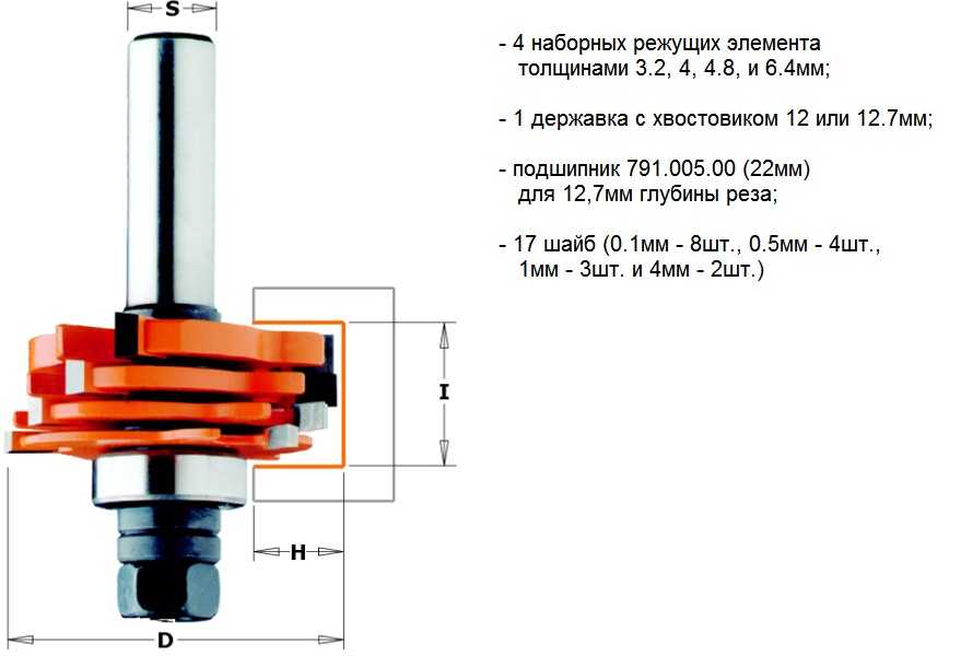 A set cutter is a set of cutting surfaces and washers that allows you to assemble a cutter of the desired shape.
 In fact, there are a lot of cutters and this is only a small fraction of what is produced. All cutters differ in the diameter of the shank, the diameter of the cutting surfaces, their height, the location of the knives, etc. As for manual milling equipment, it is enough to have a set of five of the most common cutters. If necessary, you can purchase them at any time.
Rules for working with hand milling tools
Working with power tools requires special rules, especially when there are rapidly rotating elements. In addition, as a result of work, chips are formed that fly in all directions. Despite the fact that most models are equipped with a protective shield, this does not fully protect against the flow of chips. Therefore, it is better to work with such a tool wearing safety glasses.
 The photo shows a model where a vacuum cleaner is connected to remove chips.
 General requirements
If you meet the basic requirements safe work with an electric hand router, the end result will please you with the quality of work and a safe outcome. These are the conditions:

The requirements are not very complex and quite feasible, but ignoring them means exposing yourself to danger. And one more thing, no less important, is the ability to hold a milling tool in your hands and feel how it works. If serious vibrations are felt, then you need to stop and analyze the reasons. It is possible that the cutter is dull or there is a knot. Sometimes it is necessary to correctly set the rotation speed of the cutter. Here you can experiment: either add speed or reduce it.
Edge processing: using templates
Edge processing wooden board It’s better to do it on a surface planer. If this is not possible, then you can use a hand router, although this will take some time. These works are carried out both without a template and with a template. If there are no skills or very few of them, then it is better to use a template. For processing edges, straight edge cutters are used, both with one bearing at the end of the cutting part and with a bearing at the beginning (see photo).
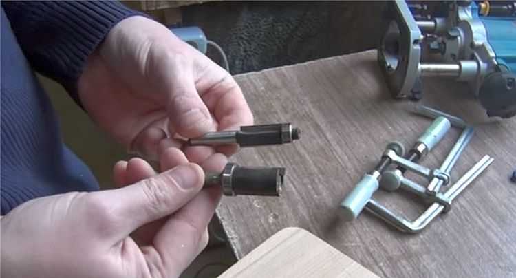 Edge cutters.
 You can use an already processed board or other flat object as a template. Moreover, the length of the template must be greater than the length of the workpiece, both at the beginning and at the end of the workpiece being processed. This will avoid unevenness at the beginning of the edge and at the end. The most important thing here is that the template or object acting as a template has a smooth and flat surface. In addition, its thickness should not be greater than the gap located between the bearing and the cutting part.
The width of the part is less than the length of the cutting part
Moreover, the longer the cutting part, the more difficult it is to work with the tool, since more effort is required. In this regard, it is better to start working with cutters that have average length cutting part. The operating principle for edge processing is as follows:
- The template is attached so that it is on required height and had a flat horizontal surface.
- The template is firmly mounted to a table or other surface.
- The cutter with the roller is installed so that the roller moves along the template, and the cutter (cutting part) moves along the workpiece. To do this, perform all the necessary manipulations with the template, workpiece and tool.
- The cutter is installed in the working position and clamped.
- After this, the tool turns on and moves along the template. In this case, you should decide on the speed of movement, which is determined by the depth of processing.
- The milling unit can be either pushed or pulled, depending on what is convenient for you.
After the first pass, you should stop and evaluate the quality of the work. If necessary, another pass can be made by adjusting the position of the tool. If the quality is satisfactory, then the clamps are removed, freeing the workpiece.
Using this approach, it is possible to remove a quarter along the edge or in some of its parts. This is done by setting the cutting edge so that it extends to the required depth into the part.
 Quarter shot on a furniture façade.
 If you replace the cutter with a shaped one and move the guide, as well as use a stop, you can actually apply a longitudinal pattern to the part (pictured below).
 Applying a longitudinal figured pattern to the workpiece.
 If you use a similar milling technique (with a template), you can easily master the technique of working with wood in general. After some time, you can abandon the templates, since their installation takes a lot of useful time.
 How to make a straight edge without a template: you can’t do this without experience.
 The width of the part is greater than the length of the cutting part
Quite often, the thickness of the workpiece is greater than the length of the cutting part of the cutter. In this case proceed as follows:
- After the first pass, the template is removed and another pass is made. In this case, the template will be the already processed part. To do this, the bearing is guided along the machined surface. If the cutting part was again missing, you will have to make another pass.
- For final processing, you should take a cutter with a bearing at the end, and the workpiece should be turned upside down, after which it is secured with clamps. As a result, the bearing will move along the machined surface. This approach makes it possible to process thick parts.
 The bearing is guided along the machined surface, and cutting edge processes the remaining part of the workpiece.
 In order to master the work of a hand milling tool, you will need a lot of rough blanks, which you don’t mind throwing away later. No one succeeded the first time. To achieve anything, you need to train hard.
Achieving Various Shaped Edges
If a figured edge is required, which is most likely necessary, then first pay attention to the condition of this edge. If it is uneven, then you will have to level it and only then begin to form a curved edge by selecting the appropriate cutter.
 Rounded edge.
 It is necessary to prepare the surface so that the cutter does not copy the curvature along which the roller will move. In this case, a sequence of actions is needed, otherwise a positive result will not work.
If you need to process a frankly curved surface, then you can’t do without a template. It can be cut from plywood, about 10 mm thick, by first applying a pattern and cutting out the template with a jigsaw. The edge of the template must be brought to perfection using a hand router.
MILLING A PLANE WITH AN END MILL
Milling a plane with an end mill is often done on a vertical milling machine. Let's consider an example of milling the plane of a block (see Fig. 84) with an end mill on a vertical milling machine.
Installation and fastening of the cutter. For processing, we will choose an end mill made of high-speed steel P18 with large teeth. With a milling width of 60 mm the end mill should have a diameter in the range of 80-100 mm. Choose a cutter with a diameter of 80 mm with 10 teeth.
The end milling cutter was selected according to GOST 9304-59. If the pantry contains cutters according to old GOST standards, which differ in diameter and width from those considered in in this example, you should select a cutter with suitable dimensions, for example with a diameter of 75 mm with a number of teeth equal to 10.
To secure an end mill in the spindle of a vertical milling machine, you must:
1) wipe the mandrel cone and the conical seat of the spindle dry;
2) insert the milling mandrel with a conical shank into the spindle socket and secure it with a tightening screw using a wrench. Here it is also necessary to ensure that the cutting direction of the cutter coincides with the direction of rotation of the spindle. The cutting direction of end mills is unambiguous, that is, it cannot be changed by turning the cutter on the mandrel with a different end, so if necessary, you have to change the direction of rotation of the spindle, i.e., reverse it;
3) put the end mill on the mandrel and tighten it with a bolt (Fig. 98).

When the cutter is fixed, it is necessary to check the runout of its end using an indicator; runout should not exceed 0.05 mm.
Setting up the machine for milling mode. The procedure for determining the elements of the milling mode is similar to that described for processing with a cylindrical cutter. The milling width is set and equal to 60 mm, cutting depth 3 mm, the feed per tooth under the conditions of a given surface cleanliness can be taken slightly larger than for a cylindrical cutter, taking into account the advantages of processing with an end mill - it is set here equal to 0.1 mm/tooth; cutting speed 27 m/min, as for a cylindrical cutter.
From the ray diagram (see Fig. 54) we find that the number of revolutions of the machine spindle at υ = 27 m/min and cutter diameter D = 80 mm lies between n 6 = 100 and n 7 = 125 rpm. We take the spindle speed equal to 100 rpm.
Here and in further examples of processing on a vertical machine, it is assumed that the work is carried out on a 6M12P vertical milling machine. If you are working on a machine of a different model, the spindle speed and table feed rate may not coincide with those indicated in the examples.
At the cutter speed n = 100 rpm, number of teeth z = 10 and feed s tooth = 0.10 mm/tooth minute feed s is determined by formula (4):
We accept the longitudinal feed available on the machine, 100 mm/min.
Let's set the gearbox dial to 100 rpm and feed box dial at 100 mm/min and determine the resulting cutting speed using formula (1):
Thus, we will carry out milling with an 80X45x32 end mill mm(cutter material - high-speed steel P18) at a cutting depth of 3 mm, milling width 60 mm, longitudinal feed 100 mm/min or 0.10 mm/tooth and cutting speed 25.1 m/min. We will mill with cooling.
After setting up the machine, milling begins.
Techniques for milling the plane of a block. The procedure for milling a plane with an end mill on a vertical milling machine is no different from milling with a cylindrical cutter on a horizontal milling machine.
When milling a plane with an end mill, the same cases of defects are possible as when milling with a cylindrical cutter (defects in size, unclean machined surface, undercutting of the surface).
Exists different types manual milling cutters, however, the most used and versatile can be called a manual plunge router, the work of which is described below. Plastic, aesthetically perfect wood and a universal hand router. This combination allows you to obtain products of almost any shape - from the simplest in the form of straight planes, to the most complex, more suitable for works of art than for utilitarian things. Working with a manual wood milling machine provides an opportunity to fully enjoy creativity, creating original, exclusive products.
Types of work performed by a milling cutter
All operations that are carried out using a manual milling cutter can be divided into several categories.Milling of grooves, grooves, quarters and other recesses in the workpiece, which can be located both along and across the layers, be open (proceed to the edge) or closed. With some exceptions, these forms fulfill certain design functions- most often form detachable and permanent connections.

Edge milling- profiling. It is used for the production of molded profile products (cornices, skirting boards, platbands, glazing beads, etc.), as well as for interior design, furniture manufacturing and various kinds of crafts. These elements, in addition to being functional, also carry a decorative load.

Milling complex surfaces and contours while creating original furniture, exclusive interiors and the manufacture of products for various purposes that claim artistic sophistication. At the same time, templates are widely used that allow you to copy repeating complex shapes with great precision, making them almost completely identical.

Milling of special elements, carrying a purely functional load. These are grooves and holes for awnings and locks, tenons, etc. In mass production, these elements are made using specialized milling cutters (filler cutters, etc.). But in everyday life, universal hand-held milling cutters can handle them quite successfully.


To give the product a certain form, it is necessary to ensure accurate positioning of the cutter relative to the workpiece in three coordinates. The vertical position of the tool is ensured by the immersion mechanism, which moves the motor with the cutter along the vertical guides of the frame and locks it in the desired height position.
Positioning in horizontal plane can be provided in various ways. Using a guide bearing mounted on the cutter, or a guide bushing attached to the bearing surface of the router, as well as a variety of special devices, supplied with milling cutters and purchased independently or made by yourself. There are a large number of manuals and recommendations describing how to work with a router using these devices, read one of them.
When using cutters with a guide bearing, the latter rolls along the edge of the workpiece or template located below or above the workpiece, thus providing a certain distance between the cutter and the part. Milling cutters that have a guide bearing and process the edges of parts are called edge cutters. They are used only for processing the edges of workpieces. Exist different shapes edge cutters.

Profile cutters(a and b) give the edge various shaped profiles that carry a decorative load.
Cone cutter(c) designed for bevelling edges at an angle of 45°.
Moulder cutter(d) used for rounding edges. It forms a quarter-circle profile and can be different sizes with a circle radius of 3-16 mm.
Disc cutter(e) cuts a horizontal groove of varying depth and width in the workpiece.
Seam cutter(f) is used for milling quarters that perform a wide variety of functions.
Fillet cutter(g) used to obtain fillets on the edge. It is used to make edges decorative.
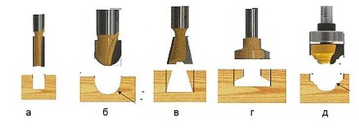
Milling cutters without guide bearings, called slotted cutters, are designed to cut the workpiece anywhere. Their use requires the use of devices (branded and homemade devices for a manual router, read), ensuring positioning of the cutter in the horizontal plane.

Rectangular slot cutter(a) is perhaps the most used. It is used for milling grooves that ensure the connection of parts - both one-piece and detachable.
Fillet cutter(b) creates semicircular grooves or grooves in the workpiece, often performing decorative functions.
V-shaped cutter(c) forms a groove with walls located at an angle of 45°. If you insert the cutter to a greater depth, you will get a groove with vertical edges. Using a V-shaped cutter, letters and various decorations are cut out.
Milling cutter dovetail" (d) usually used in furniture production when making open and hidden tenon joints.
Fastening the cutter in the router collet
The cutter can be installed both in the engine removed from the frame and in it. It is carried out in the following sequence:- The router is laid on its side.
- The spindle is prevented from turning - depending on the design of the router, wrench or a locking button.
- The clamping nut of the collet is released (if it is screwed onto the collet) or screwed on.
- The cutter shank is inserted into the collet until it stops or at least 20 mm.
- Using a wrench (if the spindle is fixed with a wrench, a second wrench is required), the clamping nut is tightened and the spindle is unlocked.
If there is no cutter in the collet, the clamping nut should not be tightened. This may damage the collet..
Working with a milling cutter involves performing various adjustment operations. One of the main ones is setting the milling depth. It may vary slightly among milling cutters different models, but its principle remains the same for all plunge routers. The essence of the setting is that when the cutter reaches the required depth, the plunge limiter rests on the turret step stop and prevents further immersion of the cutter.
Setting the milling depth: 1 - turret stop, 2 - immersion depth limiter, 3 - depth limiter locking screw, 4 - limiter slider, 5 - fine-tuning mechanism, 6 - immersion scale, 7 - spindle lock for installing the cutter.
The operation is performed in the following order:
- The milling cutter is installed with its supporting surface on the workpiece.
- The turret stop, which sets the immersion depth, is installed with its lowest stop opposite the end of the stop.
- The limiter locking screw is released, as a result of which the latter gains the ability to move freely in its guides.
- The mechanism of immersion (lowering) of the milling cutter is unlocked.
- The motor slowly lowers down until the cutter touches the part.
- The engine lowering mechanism is blocked again.
- The depth stop is lowered until it touches the lowest stop.
- The limit slider is set to "0" on the dive scale.
- The limiter rises to the position at which its slider shows on the immersion scale the value of the milling depth that needs to be set. This operation can be carried out by raising and lowering the stopper by hand (coarse setting) or using a fine adjustment mechanism (fine setting).
- The limiter locking screw is clamped, fixing the slider in the installed position.
- The immersion mechanism is unlocked, and the cutter and the motor rise upward.
Now, if you lower the motor with the cutter to the lowest position (until the end of the limiter touches the shortest pin of the turret stop), the cutter will penetrate into the workpiece to the depth the value of which is set on the scale.
If milling is carried out to a great depth, it must be carried out in stages. This is done by turning the turret stop so that during the first passes the depth stop first rests against the higher stops, and only in the final pass against the lowest stop.

Selecting the cutter rotation speed mode
Unlike rotary hammers, screwdrivers and drills, the rotation speed of the cutter is relatively high - usually over 10,000 rpm. This is explained by the fact that the faster the cutter rotates, the cleaner the cut surface is. However, too high speeds are also undesirable, since the surface being processed can become charred, and excessively increasing centrifugal forces - especially when using cutters large diameter- lead to breakdowns. Therefore, the rotation speed of the cutter is adjusted within certain limits depending on the material being processed and the diameter of the cutter.In fact, the cleanliness of the machined surface is determined not by the rotation speed of the cutter, but by the linear speed of movement of the cutting edge relative to the material. The larger the cutter diameter, the higher the linear speed. Therefore, when using large-diameter cutters, the rotation speed is set lower. For example, for a cutter with a diameter of 10 mm, the speed should be from 20,000 rpm and higher, for a cutter with a diameter of 40 mm - 10,000-12,000 rpm. Specific values are specified in the operating instructions. The rotation speed is also determined by the hardness of the material being processed. The higher the hardness, the lower the number of revolutions of the cutter should be.
After prolonged operation at low speeds, the milling cutter should be turned on for several minutes at maximum speed at Idling for engine cooling.
Cutter rotation direction
The direction of rotation of the cutter can be along or counter. In the first case, the cutting edge of the cutter moves relative to the material in the direction opposite to the movement of the router (the edge cuts into rough surface boards and comes out at the bottom of the milled groove). During counter milling, the edge of the cutter moves in the same direction as the movement of the router (plunging begins at the depth of the groove). Up milling is correct; down milling is used only in exceptional cases - when processing edges in which the arrangement of fibers leads to flakes. This method is considered unsafe, as it can lead to the router being pulled out of your hands.
Milling
Milling parts with a manual router, as a rule, involves the use of various devices to ensure the exact position of the router. Therefore, milling techniques are discussed in the article Milling devices, which describes not only proprietary devices, but also those made by hand.Before starting milling, the following must be done:
- The cutter is fixed in the collet.
- The engine speed suitable for the job is set.
- The required milling depth is set using the plunge limiter (when working with plunge cutters) or a certain value of the cutter overhang in relation to the base is fixed (when working with edge cutters).
- A guide bearing or ring (when working with edge cutters) or other device is installed to ensure the required path of the cutter. In this case, it must be specified optimal thickness cut - as a rule, no more than 3 mm.
The methods of working with a manual milling cutter differ somewhat depending on the mode in which the work is carried out. But in any case, the router is installed on a base - the workpiece or an auxiliary surface. The guide element of the router (bearing, ring, edge of the sole or other surface) is pressed against the guide edge (part, rack or template), after which the engine is turned on and the cutter first begins to immerse (if the submersible mode is used), then the router moves smoothly along the trajectory , specified by the guide element.
Basic safety precautions when working with a router
Safety precautions are described in detail in the operating instructions for the router. The most important ones that are simply vital to know include the following:- Attaching the cutter and setting the router must be done with the power cord unplugged from the outlet.
- Working with a hand router requires care and concentration. When milling, you must stand firmly on your feet and hold the router firmly in your hands. You cannot work while tired, distracted or drunk. This could result in the router being pulled out of your hands and causing serious injury.
- The workpiece must be firmly fixed, otherwise it may be torn out of place by the cutter and thrown with great force and speed.
- When the cutter comes into contact with the material, you need to be especially careful to avoid the so-called kickback- the effect when the cutter hits the material and receives a reactive blow, which can lead to the cutter being torn out of your hands, broken or injured. To prevent a kickback from occurring, you need to hold the router firmly in your hands, firmly press it to the base and smoothly move the tool. The thickness of the cut layer should not be too large - no more than 3 mm.
- Clothes should not have loose elements that could get wrapped around the cutter.
- Avoid inhalation of fine dust generated during milling. It is harmful to the lungs. Dust can be sucked out with a vacuum cleaner or a respirator can be used.
When using the content of this site, you need to put active links to this site, visible to users and search robots.
The simplest method is to directly install the cutter on the spindle and clamp it with a nut. The direction of the thread must be opposite to the direction of rotation of the spindle.
Chucks are used to install end mills on the spindle. Backed cutters are secured with a shank in a collet chuck. Single-cut, non-backed cutters are secured in special chucks with a screw.
When directly seated on the spindle (Fig. A) cutter 3 rests against the shoulder of spindle 7 and is clamped with nut 5. To change the height position of the cutter, spacer rings 2, spacers or washers 4 are used.
If the diameter of the mounting hole is larger than the diameter of the spindle, use a landing on the spindle through a bushing (Fig. b). The cutter is first secured to sleeve 1 with nut 2, and then the sleeve is installed on the spindle and secured with a tightening nut.
In the case where the spindle does not have a thread for attaching the cutter, use a collet mandrel (Fig. V). The mandrel has an inner conical split 1 and an outer 2 bushings. The cutter is installed on the outer sleeve and secured with a nut. Then the mandrel with the tool is installed on the spindle and secured by rotating the upper tightening nut. In this case, the outer bushing moves along the inner conical bushing, as a result of which its split part tightly covers the spindle.
If the machine spindle does not have axial adjustment movement, the cutter can be mounted in a setting head equipped with a device for adjusting the position of the cutter relative to work surface table (Fig. G). The position of head 2 with the cutter is adjusted with the inner sleeve loosened by rotating screw 1, which rests against the end of the spindle.
Standard fastening is common (Fig. d) cutter head on horizontal spindle two short conical collets 3, clamped with nuts 1. Pins 4 in the head body fit into the slots of the collets, preventing their rotation. When screwed in, guide screw 2 fits into the keyway of the spindle and serves to fix the head and increase the reliability of torque transmission.
IN foreign models On machine tools, hydroplastic devices for securing cutters on spindles have become widespread (Fig. e). Thin-walled bushing 2 is pressed into the cutter body 3. Inner surface The bushing is both centering and clamping. Hydroplastic 4 is injected into the cavity between the sleeve and the cutter under pressure. The pressure is created by rotating the plunger screw 5. To detach the cutter, the pressure in the cavity is reduced by unscrewing the screw 6. The fastening ensures increased accuracy of centering the cutter on the spindle 1.

Methods for attaching the milling cutting tool on machine spindles:
Backed end mills are mounted in collet chucks, non-backed end mills are mounted in special chucks with eccentricity e axis of the tool hole relative to the axis of the chuck shank (Fig. and). The cutter 2 is held in the chuck body 3 by screw 1. The chuck shank 5 is installed in the tapered hole of the spindle 6 and tightened with a nut 4. The chuck body has six holes for screwing in balancing screws.
The milling operator must know the type and number of the spindle socket cone of his machine and the mounting dimensions of the front end of the spindle.
The dimensions of the spindle socket cone and the mounting flange of the front end of the spindle of milling machines are standardized by GOST 836-47, and therefore end mills and milling arbors manufactured with a standard shank fit these machines.
In Fig. 59 shows the front end of a milling machine spindle. The inner cone 2, into which the tool shank is inserted, is made very steep. Rotation of the tool is transmitted by drivers 5 inserted into grooves in the end of the spindle and screwed in with screws. The tool, which is mounted directly on the mounting flange 1, is centered by a cylindrical sharpening of the front end and is secured with four screws inserted into holes 4.
Fastening the shear cutters. Shell cutters are mounted on mandrels, which are secured in the machine spindle.
In Fig. 60 shows mandrels having a conical shank Y, which corresponds to the conical socket of the front end of the spindle of domestic milling machines and is centered in it. Recesses 2 in the mandrel flange are put on drivers inserted into grooves at the end of the spindle.
The mandrel shown in Fig. 60, a, is intended for fastening cutters operating under high forces. It has a large length, allowing the use of an additional trunk earring. The mandrel shown in Fig. 60, b, is intended for lighter work.

The mandrels shown in Fig. 60, a and b, are called center. The center mandrel is fixed at one end in the slot of the machine spindle, and the other is supported by the trunk earring bearing.

The mandrel shown in Fig. 60, in, is called an end mill, since one end of it is fixed in the socket of the machine spindle, and at the other end a mounted cutter is installed, which works together with a mandrel, like an end mill.
Fastening cutters to center mandrels. In Fig. 61 shows various cases of attaching shell cutters to center mandrels. The tapered mandrel shank is included in conical hole 8 of the spindle, the other end goes into bearing 1 of the earring.
In Fig. 61, and shows the mounting on a mandrel of a cylindrical cutter 5 with helical teeth. The cutter is put on the middle (working) part of the mandrel and can be installed anywhere on the mandrel using installation rings 3, 4, 6 and 7. These rings are put on the mandrel in the same way as cutter 5. The leftmost ring 7 rests against the shoulder, located on the mandrel, and the rightmost ring 3 is supported by a nut 2 screwed onto the end of the mandrel.
In Fig. 61, b shows the mounting of several cutters on a mandrel close to one another (a set of cutters). It can be seen from the drawing that the width of the mounting rings is different here.
The normal set of mounting rings supplied with the milling machine consists of rings with a width of 1 to 50 mm, namely: 1.0; 1.1; 1.2; 1.25; 1.3; 1.4; 1.5; 1.75; 2.0; 2.5; 3.0 3.25; 5.0; 6.0; 7.5; 8.0;* 10 20; thirty; 40 and 50 mm.
Using mounting rings, the cutters can be secured at a certain distance from each other. In Fig. 61, c shows the fastening of two cutters at a distance A from each other. This distance is established by selecting rings of the required width.
Sometimes, when adjusting the distance between the cutters on the mandrel, it is necessary to place thin spacers made of aluminum or copper foil and even writing or tissue paper between the adjusting rings, since using the rings included in the set it is impossible to obtain the required distance between the cutters.
Innovative milling machine operator V. A. Goryainov designed an adjustable setting ring (Fig. 62), which allows you to quickly ensure the required distance between cutters with an accuracy of 0.01 mm. The distance between the cutters 4 is adjusted by turning the adjustable adjusting ring 6 with a key 5, which has a dial with 0.01 mm graduations. Pre-installation milling cutters are produced using conventional mounting rings 3.

Cutters of small diameters, operating with little effort, are kept from turning on the mandrel by frictional forces that arise between the ends of the cutter and the ends of the rings due to tightening with a nut. But during heavy work, this friction is not enough, and the cutter is held on the mandrel using a key. A keyway is milled along the entire length of the middle (working) part of the mandrel; a key is attached to it, onto which the cutter is put. In this case, the rings are also placed on the key.
The diameters of the holes in attachment cutters and rings, as well as the outer diameters of the working part of the milling mandrels, are made only in certain sizes. The following mandrel diameters are accepted at domestic factories: 10, 13, 16, 22, 27, 32, 40 and 50 mm. Keyways and keys are also made in certain sizes, so that the milling cutters, mandrels, rings and keys of the same number available in the tool store will definitely fit each other.
Milling mandrels should not have runout, nicks or dents. There should be no nicks or burrs at the ends of the rings. The ends of the rings must be parallel and perpendicular to the axis of the ring.

When installing cutters, you need to place them as close as possible to the front end of the machine spindle to reduce the load on the mandrel. If for some reason this fails, then an additional shackle must be installed, which relieves the load on the milling mandrel. The procedure for installing and securing the cutter on the mandrel and securing the mandrel in the slot of the machine spindle is described in detail when considering setting up the machine.
Fastening cutters to end mandrels. End mills and disk cutters that do not require a long reach are secured to end mandrels.
In Fig. 63 shows the end mandrel. The conical end 1 is inserted into the conical socket of the machine spindle. The cutter is put on the cylindrical part of the mandrel and tightened with screw 3. Key 2 prevents the cutter from turning on the mandrel.
Fastening cutters with conical and cylindrical shanks. Cutters with a conical shank, the size of which coincides with the dimensions of the conical socket of the spindle, are inserted with the shank into the spindle and secured in it using a tightening screw (ramrod). This is the easiest way to secure a cutter on both horizontal and vertical milling machines.
If the size of the cutter shank taper smaller size the cone of the spindle socket, then resort to adapter bushings (Fig. 64). Outer cone such a sleeve corresponds to the slot of the machine spindle, and the inner cone corresponds to the shank of the cutter. The adapter sleeve with the inserted cutter is installed in the spindle and tightened using a tightening screw (ramrod).

The cutters with a cylindrical shank are secured using the chuck shown in Fig. 65. The cutter is inserted into the cylindrical hole of the expanding collet of the chuck 1 and secured by means of a nut 2 located at the front end of the chuck and enclosing the expanding sleeve 3 with its shoulders. The chuck with the cutter on is installed in the spindle of a horizontal or vertical milling machine and secured with a tightening screw. The cutter is removed after releasing nut 2.

Fastening of large-diameter sheath cutters. Prefabricated end mills with a diameter of 80 mm and above are manufactured with attachments.


The mounting holes of such cutters are made conical or cylindrical.
Milling cutters with a conical mounting hole (Fig. 66, a) are placed on the cone 1 of a special milling mandrel (Fig. 66, b) and secured to it using liner 2 and screw 3. The insert 2 fits into the grooves 4 in the cutter body. The mandrel with the cutter is secured in the conical socket of the spindle using a tightening screw (ramrod) by screwing it into the threaded hole 5 of the mandrel. To prevent the milling mandrel from turning in the conical seat of the spindle, the mandrel has two grooves 5 that fit into the cracks 3 at the end of the front end of the machine spindle (see Fig. 59).
Cutters with a cylindrical mounting hole (Fig. 67) are mounted on the cylindrical end of 1 spindle (see Fig. 59) and attached directly to its end using four screws included in the corresponding threaded holes spindle end.