The bridge is across the river, across the ravine, and also across the road. But have you ever heard the phrase "diode bridge"? What kind of bridge is it? But we will try to find an answer to this question.
The word combination "diode bridge" is derived from the word "diode". It turns out that the diode bridge should consist of diodes. But if there are diodes in the diode bridge, then the diode will pass in one direction electricity, but not in the other. We used this property of diodes to determine their performance. Who does not remember how we did it, then you are here. Therefore, a diode bridge is used to obtain a constant voltage from an alternating voltage.
And here is the diode bridge diagram:
Sometimes in the diagrams it is also denoted like this:
As we can see, the circuit consists of four diodes. But in order for the diode bridge circuit to work, we must correctly connect the diodes, and correctly apply an alternating voltage to them. On the left we see two "~" icons. We apply alternating voltage to these two terminals, and remove the constant voltage from the other two terminals: from the plus and minus.
In order to convert an alternating voltage into a constant voltage, one diode can be used for rectifying, but it is not desirable. Let's take a look at the drawing:
The alternating voltage changes over time. The diode passes voltage through itself only when the voltage is above zero, but when it becomes below zero, the diode turns off. I think everything is elementary and simple. The diode cuts off the negative half-wave, leaving only the positive half-wave, which we see in the picture above. And the whole beauty of this simple circuit is that we get a constant voltage from an alternating one. The problem is that we are wasting half the power of the AC voltage. The diode stupidly cuts it off.
To remedy this situation, a diode bridge circuit was developed. Diode bridge"flips" the negative half-wave, turning it into a positive half-wave. Thus, our capacity is preserved. Great isn't it?

At the output of the diode bridge, we have a constant ripple voltage, often twice as high as the mains frequency: 100 Hz.
I think there is no need to write how the circuit works, it will not be useful to you anyway, the main thing is to remember where the alternating voltage clings, and where the constant pulsating voltage comes from.
Let's take a look at how a diode and a diode bridge work in practice.
Let's start with a diode.
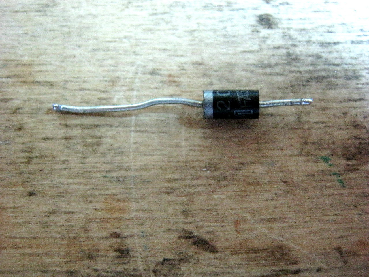
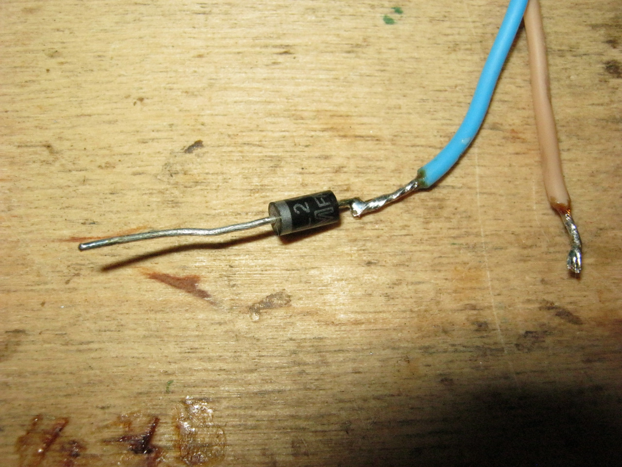
I dropped it out of the computer's power supply. The cathode can be easily identified by the strip. Almost all manufacturers show the cathode with a strip or dot.
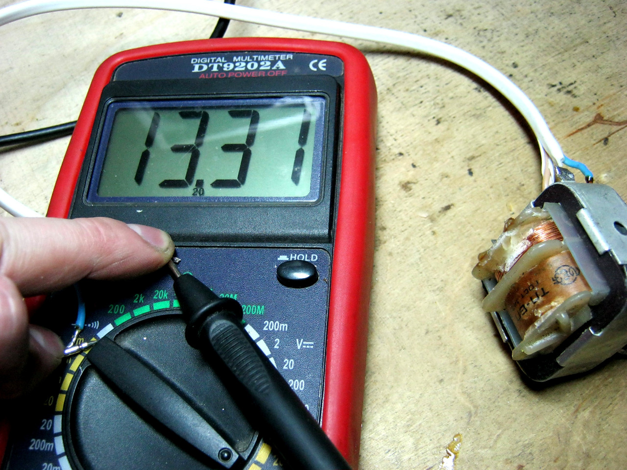
To make our experiments safe, I took a step-down transformer, which converts from 220 volts to 12 volts. Who does not know how he does it, you can read the article on the device of the transformer.
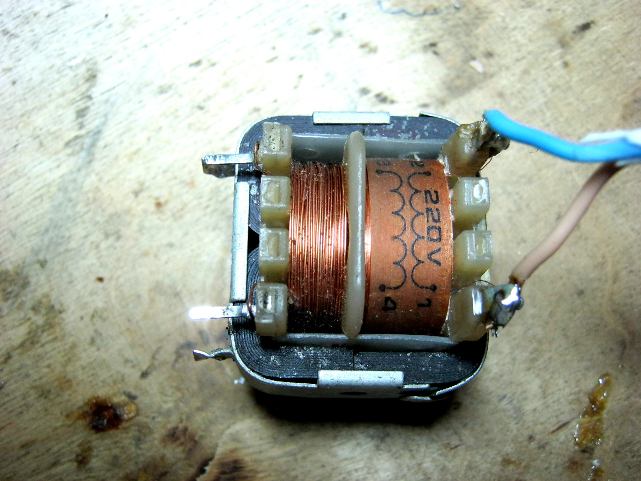
We hook 220 Volts to the primary winding, and remove 12 Volts from the secondary. The cartoon shows a little more, since no load is connected to the secondary winding. The transformer operates on the so-called " Idling".
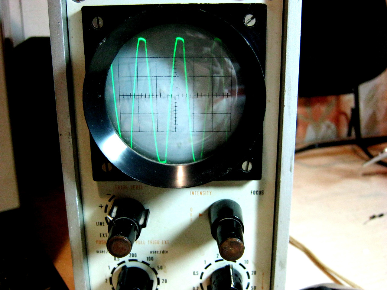
Let's take a look at the oscillogram that comes from the secondary trance winding. The maximum voltage amplitude is easy to calculate. If you don't remember how to calculate, you can take a look at the article Oscilloscope. Basics of operation. 3.3x5 = 16.5V is the maximum voltage value. And if we divide the maximum value of the amplitude by the root of two, then we get somewhere 11.8 Volts. This is the effective voltage value. Oscillus does not lie, everything is OK.
I repeat once again, you could have used 220 volts, but 220 volts is no joke, so I lowered the alternating voltage.
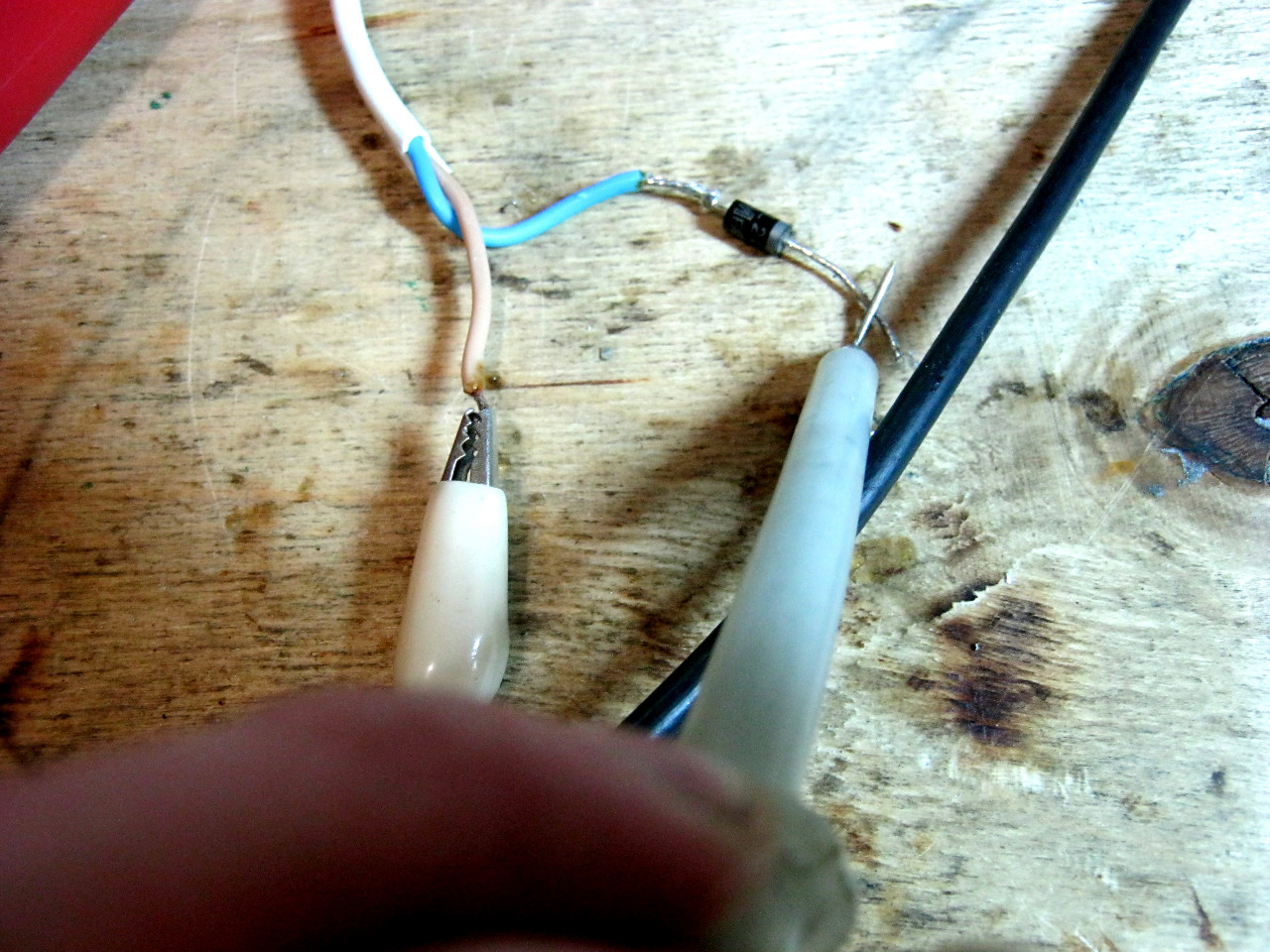
We solder our diode to one end of the secondary trance winding.
We cling again with the probes of the oscillator
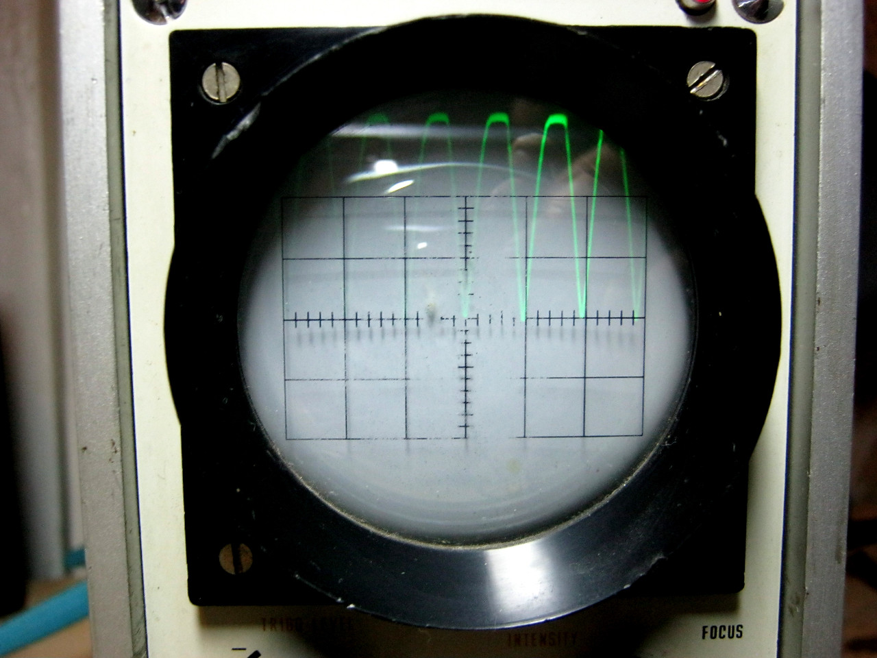
We look at the oscilla

Where is the bottom of the image? It was cut off by a diode. The diode left only the upper part, that is, the one that is positive. And since he cut off the lower part, then he therefore cut off the power.
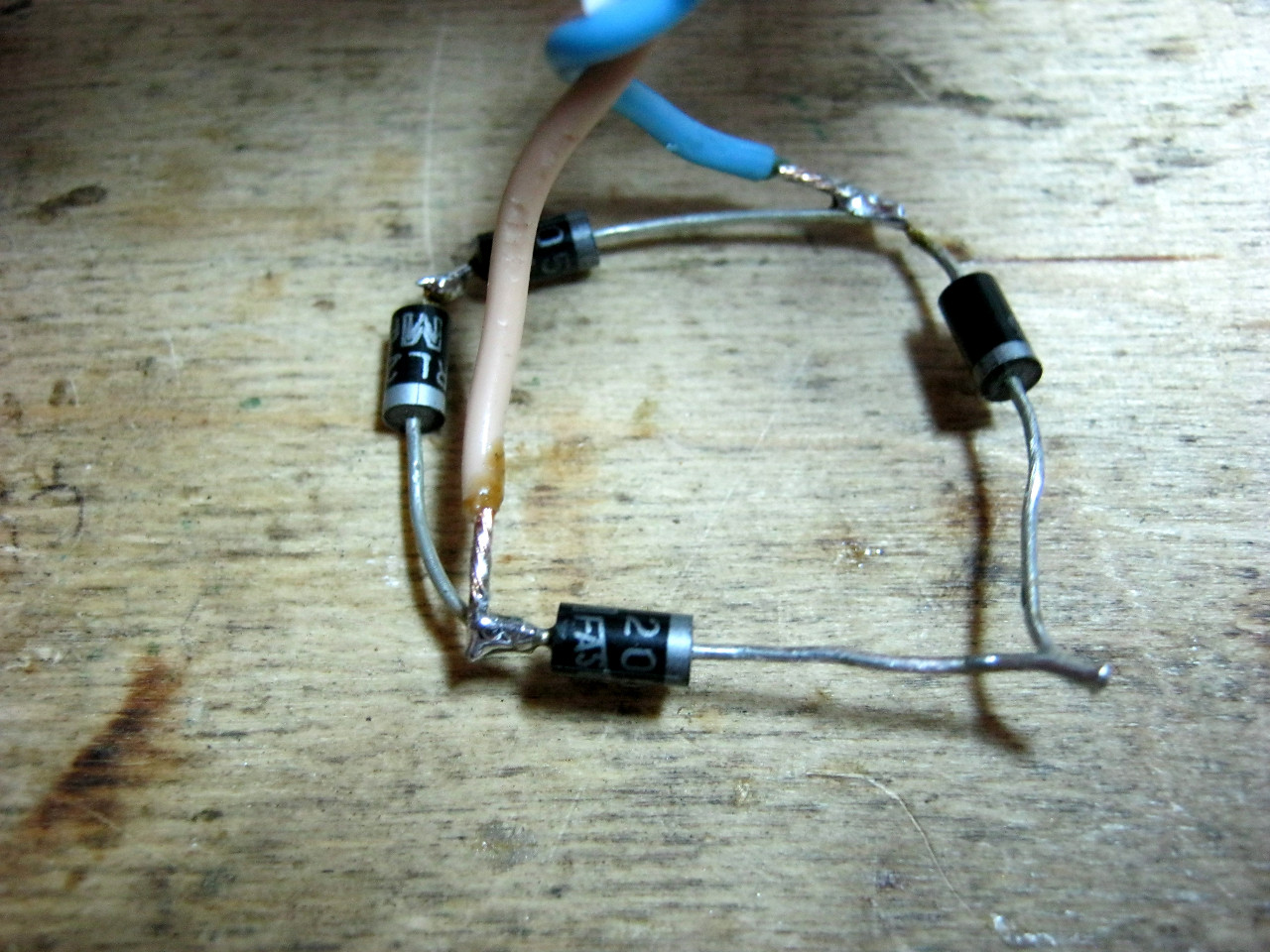
We find three more such diodes and solder the diode bridge.

We cling to the secondary trance winding according to the diode bridge scheme.
From the other two ends, remove the constant pulsating voltage with the oscilla- tion probes and look at the oscilla- tion.
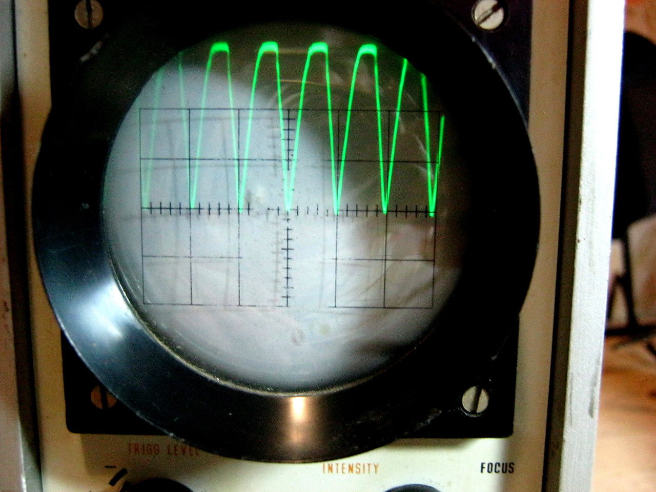
Here, now everything is fine, and the power has not disappeared anywhere :-).
In order not to mess with diodes, the developers placed all four diodes in one case. The result is a very compact and convenient diode bridge. I think you can guess where is imported and where is Soviet))).

And here is the Soviet one:

How did you guess? :-) For example, on the Soviet diode bridge, the contacts to which an alternating voltage must be applied (by the "~" icon) are shown, and the contacts from which the constant pulsating voltage must be removed ("+" and "-") are shown.
Let's check the imported diode bridge. To do this, we hook two of his contacts to the break, and from the other two contacts we take readings on the oscilloscope.

And here is the oscillogram:
So the imported diode bridge is working chiki-bunches.
In conclusion, I would like to add that the diode bridge is used in almost all radio equipment that consumes voltage from the network, whether it is a simple TV or even a charger for cell phone... The diode bridge is checked by the serviceability of all its diodes.
So, my dear ones, we have collected our schematic and it's time to check it, test it and enjoy this happiness. The next step is to connect the circuit to a power source. Let's get started. We will not dwell on batteries, accumulators and other gadgets of power, we will go directly to the mains power supplies. Consider here existing schemes straightening, how they work and what they can do. For experiments, we need a single-phase (at home from an outlet) voltage and the corresponding parts. Three-phase rectifiers are used in industry, we will not consider them either. If you grow up as electricians, then please.
The power supply consists of several of the most important details: Mains transformer - in the diagram it is indicated similar to the figure,
Rectifier - its designation can be different. The rectifier consists of one, two or four diodes, depending on which rectifier. Now we will figure it out.
a) - a simple diode.
b) - diode bridge. Consists of four diodes, included as shown.
c) - the same diode bridge, just drawn in a simpler way for brevity. The pin assignments are the same as for the bridge under the letter b).
Filter condenser. This thing is unchanged both in time and in space, denoted as follows:
A capacitor has many designations, as many as there are designation systems in the world. But in general they are all alike. Let's not get confused. And for clarity, let's draw a load, let's designate it as Rl - load resistance. This is our scheme. We will also outline the contacts of the power supply to which we will connect this load.
Further - a couple of postulates.
- The output voltage is defined as Uconst = U * 1.41. That is, if we have 10 volts of alternating voltage on the winding, then on the capacitor and on the load we will get 14.1V. Like that.
- Under load, the voltage sags a little, and how much depends on the design of the transformer, its power and capacitor capacity.
- Rectifier diodes should be 1.5-2 times more current than necessary. For stock. If the diode is intended for installation on a radiator (with a nut or a hole for a bolt), then at a current of more than 2-3A it must be placed on a radiator.
Let me also remind you what bipolar voltage is. If someone has forgotten. We take two batteries and connect them in series. The middle point, that is, the connection point of the batteries, will be called a common point. It is popularly known as mass, earth, body, common wire. The bourgeois call it GND (ground), often denoted as 0V (zero volts). Voltmeters and oscilloscopes are connected to this wire, relative to it, input signals are supplied to the circuits and output signals are removed. Therefore, its name is a common wire. So, if we connect the tester with a black wire to this point and measure the voltage on the batteries, then on one battery the tester will show plus 1.5 volts, and on the other - minus 1.5 volts. This voltage +/- 1.5V is called bipolar. Both polarities, that is, plus and minus, must necessarily be equal. That is, +/- 12, +/- 36V, +/- 50, etc. A sign of a bipolar voltage - if there are three wires from the circuit to the power supply (plus, common, minus). But this is not always the case - if we see that the circuit is powered by voltages of +12 and -5, then such a power supply is called two-level, but there will still be three wires to the power supply. Well, if as many as four voltages go to the circuit, for example +/- 15 and +/- 36, then this power supply will simply be called - bipolar two-level.
Well, now to the point.
1. Bridge rectifier circuit.
The most common scheme. Allows you to get a unipolar voltage from one transformer winding. The circuit has minimal voltage ripple and is simple in design.

2. Half-wave circuit.
Just like the bridge, it prepares us a unipolar voltage from one winding of the transformer. The only difference is that this circuit has twice the ripple compared to the bridge, but one diode instead of four greatly simplifies the circuit. It is used at low load currents, and only with a transformer, much higher load power, because such a rectifier causes one-sided magnetization reversal of the transformer.

3. Full-wave with a midpoint.
Two diodes and two windings (or one winding with a midpoint) will supply us with a low-ripple voltage, plus we will get lower losses in comparison with a bridge circuit, because we have 2 diodes instead of four.

4. Bridge circuit of a bipolar rectifier.
For many it is a sore subject. We have two windings (or one with a midpoint), we remove two identical voltages from them. They will be equal, the ripple will be small, since the circuit is bridge, the voltage on each capacitor is calculated as the voltage on each winding multiplied by the root of two - everything is as usual. The wire from the midpoint of the windings equalizes the voltages on the capacitors if the positive and negative loads are different.

5. Circuit with voltage doubling.
These are two half-wave circuits, but with diodes turned on differently. It is used if we need to get double the voltage. The voltage across each capacitor will be determined by our formula, and the total voltage across them will be doubled. Like the half-wave circuit, this one also has large ripple. You can see a bipolar output in it - if the midpoint of the capacitors is called ground, it turns out as in the case of batteries, take a closer look. But a lot of power cannot be removed from such a scheme.
6. Receiving a bipolar voltage from two rectifiers.
It is not at all necessary that these were the same power supplies - they can be either different in voltage or different in power. For example, if our circuit consumes 1A for + 12 volts, and 0.5A for -5 volts, then we need two power supplies - + 12V 1A and -5V 0.5A. You can also connect two identical rectifiers to get a bipolar voltage, for example, to power an amplifier.
7. Parallel connection of identical rectifiers.
It gives us the same voltage, only with twice the current. If we connect two rectifiers, then we have a double increase in current, three - a triple, etc.
Well, if you, my dears, everything is clear, then I’ll ask, perhaps, homework... Formula for calculating the capacitance of a filter capacitor for a full-wave rectifier: 
For a half-wave rectifier, the formula is slightly different: 
The two in the denominator is the number of "ticks" of straightening. For a three-phase rectifier, the denominator will be a three.
In all formulas, variables are called like this:
Cf - capacitance of the filter capacitor, μF
Ro - output power, W
U - output rectified voltage, V
f - frequency of alternating voltage, Hz
dU - ripple swing, V
For reference - permissible ripple:
Microphone amplifiers - 0.001 ... 0.01%
Digital technology - ripple 0.1 ... 1%
Power amplifiers - ripple of a loaded power supply 1 ... 10%, depending on the quality of the amplifier.
These two formulas are valid for voltage rectifiers with a frequency of up to 30 kHz. On higher frequencies electrolytic capacitors lose their efficiency and the rectifier is calculated a little differently. But that is another topic.
A diode bridge will help to convert alternating current into direct current - the circuit and principle of operation of this device are given below. In a conventional lighting circuit, an alternating current flows, which changes its magnitude and direction 50 times within one second. Its transformation into a permanent one is a fairly common necessity.
The principle of operation of a semiconductor diode
Rice. 1The name of the described device clearly indicates that this design consists of diodes - semiconductor devices that conduct electricity well in one direction and practically do not conduct it in the opposite direction. Picture of this device (VD1) on schematic diagrams is shown in Fig. 2c. When the current flows through it in the forward direction - from the anode (left) to the cathode (right), its resistance is small. When the direction of the current changes to the opposite, the resistance of the diode increases many times. In this case, a reverse current that is little different from zero flows through it.
Therefore, when an alternating voltage U in (left graph) is applied to the circuit containing the diode, electricity flows through the load only during positive half-periods, when a positive voltage is applied to the anode. Negative half-periods are "cut off", and there is practically no current in the load resistance at this time.
Strictly speaking, the output voltage U out (right graph) is not constant, although it flows in one direction, but pulsating. It is easy to understand that the number of its pulses (pulsations) per second is equal to 50. This is not always acceptable, but the ripple can be smoothed out if a capacitor is connected in parallel with the load, which has enough large capacity... Charging during voltage pulses, in the intervals between them, the capacitor is discharged to the load resistance. Ripples are smoothed out, and the voltage becomes close to constant.
A rectifier made in accordance with this scheme is called a half-wave rectifier, since it uses only one half-cycle of the rectified voltage. The most significant disadvantages of such a rectifier are as follows:
- increased degree of rectified voltage ripple;
- low efficiency;
- large weight of the transformer and its irrational use.
Therefore, such schemes are used only for powering devices. low power... To remedy this undesirable situation, full-wave rectifiers have been developed that convert negative half-waves into positive ones. This can be done in different ways, but the easiest way is to use a diode bridge.
 Rice. 2
 A diode bridge is a full-wave rectification circuit containing 4 diodes instead of one (Fig. 2c). In each half-cycle, two of them are open and pass electricity in the forward direction, and the other two are closed, and no current flows through them. During the positive half cycle, a positive voltage is applied to the VD1 anode and a negative voltage to the VD3 cathode. As a result, both of these diodes are open, and VD2 and VD4 are closed.
During the negative half cycle, a positive voltage is applied to the VD2 anode and a negative voltage to the VD4 cathode. These two diodes open, and those open during the previous half cycle are closed. The current flows through the load resistance in the same direction. In comparison with a half-wave rectifier, the number of ripples doubles. The result is a higher degree of smoothing with the same filter capacitor capacity, an increase in the efficiency of the transformer used in the rectifier.
A diode bridge can not only be assembled from individual elements, but also manufactured as monolithic construction(diode assembly). It is easier to mount, and the diodes are usually selected according to their parameters. It is also important that they operate in the same thermal conditions. The disadvantage of a diode bridge is the need to replace the entire assembly if even one diode fails.
Even closer to constant, there will be a pulsating rectified current, which makes it possible to obtain a three-phase diode bridge. Its input is connected to a three-phase source. alternating current(generator or transformer), and the output voltage is almost the same as constant voltage, and it is even easier to smooth it out than after full-wave rectification.
Diode bridge rectifier

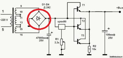
A diagram of a full-wave rectifier based on a diode bridge, suitable for self-assembly, is shown in Fig. 3a. The voltage taken from the secondary lowering winding of the transformer T is rectified.To do this, a diode bridge must be connected to the transformer.
The pulsating rectified voltage is smoothed by an electrolytic capacitor C, which has a sufficiently large capacitance - usually of the order of several thousand μF. Resistor R acts as the idle load of the rectifier. In this mode, the capacitor C is charged to an amplitude value that is 1.4 (root of two) times higher than the effective value of the voltage taken from the secondary winding of the transformer.
As the load increases, the output voltage decreases. You can get rid of this drawback by connecting the simplest transistor stabilizer to the rectifier output. In schematic diagrams, the image of a diode bridge is often simplified. In fig. 3b shows how the corresponding fragment in Fig. 3a.
It should be noted that although the forward resistance of the diodes is small, it is nonetheless non-zero. For this reason, they heat up in accordance with the Joule-Lenz law, the stronger, the greater the value of the current flowing through the circuit. Powerful diodes are often installed on heat sinks (radiators) to prevent overheating.
A diode bridge is practically required element any electronic device mains powered, whether it be a computer or a rectifier for charging a mobile phone.
Related entries:
In many electronic devices operating at 220 volts alternating current, diode bridges are installed. The 12 volt diode bridge circuit allows you to effectively perform the AC rectification function. This is because most devices use direct current to operate.
How does a diode bridge work?
An alternating current, having a certain varying frequency, is applied to the input contacts of the bridge. At outputs with positive and negative value a unipolar current is formed with increased ripple, significantly exceeding the frequency of the current supplied to the input.
The pulsations that appear must be removed, otherwise electronic circuit will not be able to work normally. Therefore, the circuit contains special filters, which are electrolytic with a large capacity.
The bridge assembly itself consists of four diodes with the same parameters. They are connected in a common circuit and are located in a common housing.
The diode bridge has four leads. AC voltage is connected to two of them, and the other two are positive and negative outputs of the pulsating rectified voltage.

The rectifier bridge in the form of a diode assembly has significant technological advantages... Thus, on printed circuit board one monolithic part is installed at once. During operation, the same thermal conditions are provided for all diodes. Price general assembly below four diodes separately. However, this part has a serious drawback. If at least one diode fails, the entire assembly must be replaced. If desired, any general scheme can be replaced by four separate parts.
The use of diode bridges
Any devices and electronics that use alternating electric current to power them have a 12 volt diode bridge circuit. It is used not only in transformer, but also in pulse rectifiers. The most characteristic pulse unit is the computer's power supply.
In addition, diode bridges are used in compact fluorescent lamps or in energy saving lamps... They give a very good effect when used in electronic ballasts. They are widely used in all models of modern devices.
How to make a diode bridge