Several diagrams are given simple devices and units that can be made by beginning radio amateurs.
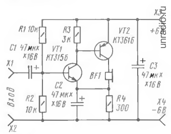
Single-stage AF amplifier
This simplest design, which allows you to demonstrate the amplification capabilities of the transistor. However, the voltage gain is small - it does not exceed 6, so the scope of application of such a device is limited.
However, you can connect it to, say, a detector radio (it should be loaded with a 10 kOhm resistor) and use the BF1 headset to listen to broadcasts from a local radio station.
The amplified signal is supplied to input jacks X1, X2, and the supply voltage (as in all other designs of this author, it is 6 V - four galvanic elements with a voltage of 1.5 V each connected in series) is supplied to jacks X3, X4.
Divider R1R2 sets the bias voltage at the base of the transistor, and resistor R3 provides current feedback, which helps temperature stabilization of the amplifier.
Rice. 1. Circuit diagram of a single-stage AF amplifier using a transistor.
How does stabilization occur? Let us assume that, under the influence of temperature, the collector current of the transistor has increased. Accordingly, the voltage drop across resistor R3 will increase. As a result, the emitter current will decrease, and therefore the collector current will decrease - it will reach its original value.
The load of the amplifier stage is a headphone with a resistance of 60.. 100 Ohms. It is not difficult to check the operation of the amplifier; you need to touch the input jack X1, for example, with tweezers you should hear a faint buzzing sound in the phone, as a result of alternating current pickup. The collector current of the transistor is about 3 mA.
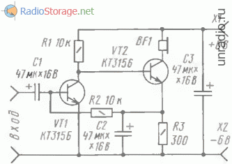
Two-stage ultrasonic amplifier using transistors of different structures
It is designed with direct coupling between stages and deep negative feedback DC, which makes its mode independent of temperature environment. The basis of temperature stabilization is resistor R4, which works similarly to resistor R3 in the previous design
The amplifier is more “sensitive” compared to a single-stage amplifier - the voltage gain reaches 20. An alternating voltage with an amplitude of no more than 30 mV can be supplied to the input jacks, otherwise distortion will occur, which can be heard in the headphone.
Check the amplifier by touching the input jack X1 with tweezers (or just a finger) - the phone will ring loud noise. The amplifier consumes a current of about 8 mA.
Rice. 2. Diagram of a two-stage AF amplifier using transistors of different structures.
This design can be used to amplify weak signals, such as from a microphone. And of course, it will significantly enhance the signal 34 removed from the load of the detector receiver.
Two-stage ultrasonic amplifier with transistors of the same structure
Here, a direct connection between the cascades is also used, but the stabilization of the operating mode is somewhat different from previous designs.
Let's assume that the collector current of transistor VT1 has decreased. The voltage drop across this transistor will increase, which will lead to an increase in the voltage across resistor R3 connected in the emitter circuit of transistor VT2.
Due to the connection of the transistors through resistor R2, the base current of the input transistor will increase, which will lead to an increase in its collector current. As a result, the initial change in the collector current of this transistor will be compensated.
Rice. 3. Diagram of a two-stage AF amplifier using transistors of the same structure.
The sensitivity of the amplifier is very high - the gain reaches 100. The gain strongly depends on the capacitance of capacitor C2 - if you turn it off, the gain will decrease. The input voltage should be no more than 2 mV.
The amplifier works well with a detector receiver, an electret microphone and other weak signal sources. The current consumed by the amplifier is about 2 mA.
It is made on transistors of different structures and has a voltage gain of about 10. The highest input voltage can be 0.1 V.
The first two-stage amplifier is assembled on transistor VT1, the second is assembled on VT2 and VT3 of different structures. The first stage amplifies the signal 34 in voltage and both half-waves are equal. The second one amplifies the signal by current, but the cascade on transistor VT2 “works” at positive half-waves, and on transistor VT3 at negative half-waves.
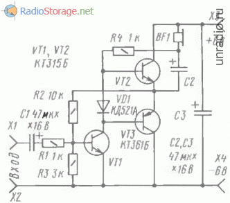
Rice. 4. Push-pull AF power amplifier using transistors.
The direct current mode is chosen such that the voltage at the point of connection of the emitters of the transistors of the second stage is equal to approximately half the voltage of the power source.
This is achieved by turning on resistor R2 feedback The collector current of the input transistor, flowing through the diode VD1, leads to a voltage drop across it. which is the bias voltage at the bases of the output transistors (relative to their emitters), it allows you to reduce distortion of the amplified signal.
The load (several parallel-connected headphones or a dynamic head) is connected to the amplifier through an oxide capacitor C2.
If the amplifier will operate on a dynamic head (with a resistance of 8 - 10 Ohms), the capacitance of this capacitor should be at least twice as large. Pay attention to the connection of the load of the first stage - resistor R4. Its upper pin in the circuit is not connected to the power supply positive, as is usually done , and with the lower load terminal.
This is the so-called voltage boost circuit, in which a small positive feedback voltage is supplied to the base circuit of the output transistors, equalizing the operating conditions of the transistors.
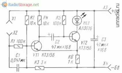
Two-level voltage indicator
Such a device can be used. for example, to indicate the “depletion” of the battery or to indicate the level of the reproduced signal in a household tape recorder. The indicator layout will demonstrate the principle of its operation.
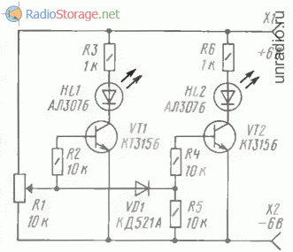
Rice. 5. Scheme of a two-level voltage indicator.
In the lower position of the engine according to the diagram variable resistor R1, both transistors are closed, LEDs HL1, HL2 are off. When the resistor slider moves upward, the voltage across it increases. When it reaches the opening voltage of the transistor VT1, the HL1 LED will flash
If you continue to move the engine. the moment will come when transistor VT2 opens after diode VD1. The HL2 LED will also light up. In other words, a low voltage at the indicator input causes only the HL1 LED to glow, and more than both LEDs.
Smoothly reducing the input voltage with a variable resistor, we note that first the HL2 LED goes out, and then HL1. The brightness of the LEDs depends on the limiting resistors R3 and R6; as their resistances increase, the brightness decreases.
To connect the indicator to a real device, you need to disconnect the upper terminal of the variable resistor in the diagram from the positive wire of the power source and apply a controlled voltage to the extreme terminals of this resistor. By moving its slider, you select the indicator's response threshold.
When monitoring only the voltage of the power source, it is permissible to install an AL307G green LED in place of HL2.
It produces light signals according to the principle less than normal- the norm is more than the norm. For this purpose, the indicator uses two red LEDs and one green LED.

Rice. 6. Three-level voltage indicator.
At a certain voltage on the motor of the variable resistor R1 (the voltage is normal), both transistors are closed and only the green LED HL3 (works). Moving the resistor slide up in the circuit leads to an increase in voltage (more than normal), and transistor VT1 opens on it.
LED HL3 goes out and HL1 lights up. If the slider is moved down and thus the voltage on it is reduced (‘less than normal’), transistor VT1 will close and VT2 will open. The following picture will be observed: first the HL1 LED will go out, then HL3 will light up and soon go out, and finally HL2 will flash.
Due to the low sensitivity of the indicator, a smooth transition is obtained from the extinguishing of one LED to the lighting of another. For example, HL1 has not yet gone out completely, but HL3 is already lighting up.
Schmitt trigger
As you know, this device is usually used to convert a slowly varying voltage into a rectangular signal. When the variable resistor R1 slider is in the lower position in the circuit, the transistor VT1 is closed.
The voltage at its collector is high, as a result, transistor VT2 is open, which means that LED HL1 is lit. A voltage drop is formed across resistor R3.

Rice. 7. A simple Schmitt trigger on two transistors.
By slowly moving the variable resistor slider up the circuit, it will be possible to reach a moment when transistor VT1 opens abruptly and closes VT2. This will happen when the voltage at the base of VT1 exceeds the voltage drop across resistor R3.
The LED will go off. If you then move the slider down, the trigger will return to its original position - the LED will flash. This will happen when the voltage on the slider is less than the LED turn-off voltage.
Waiting multivibrator
Such a device has one stable state and transitions to another only when an input signal is applied. In this case, the multivibrator generates a pulse of its duration regardless of the duration of the input signal. Let's verify this by conducting an experiment with a prototype of the proposed device.
Rice. 8. Schematic diagram waiting multivibrator.
In the initial state, transistor VT2 is open, LED HL1 lights up. It is now enough to short-circuit sockets X1 and X2 so that a current pulse through capacitor C1 opens transistor VT1. The voltage at its collector will decrease and capacitor C2 will be connected to the base of transistor VT2 in such a polarity that it will close. The LED will go off.
The capacitor will begin to discharge, the discharge current will flow through resistor R5, keeping transistor VT2 in the closed state. As soon as the capacitor is discharged, transistor VT2 will open again and the multivibrator will go back into standby mode.
The duration of the pulse generated by the multivibrator (duration of being in an unstable state) does not depend on the duration of the triggering one, but is determined by the resistance of resistor R5 and the capacitance of capacitor C2.
If you connect a capacitor of the same capacity in parallel with C2, the LED will remain in the off state twice as long.
I. Bokomchev. R-06-2000.
 WITH where to start studying radio electronics? How to build your first electronic circuit? Is it possible to quickly learn to solder? It is for those who ask such questions that this section was created. "Start"
.
WITH where to start studying radio electronics? How to build your first electronic circuit? Is it possible to quickly learn to solder? It is for those who ask such questions that this section was created. "Start"
.
N and pages This section publishes articles about what any beginner in radio electronics should know first. For many radio amateurs, electronics, which was once just a hobby, over time has grown into a professional environment and has helped in finding a job and choosing a profession. Taking the first steps in studying radioelements and circuits, it seems that all this is terribly complicated. But gradually, as knowledge accumulates, the mysterious world of electronics becomes more understandable.
E if If you have always been interested in what is hidden under the cover of an electronic device, then you have come to the right place. Perhaps a long and exciting journey in the world of radio electronics will begin for you from this site!
To go to the article you are interested in, click the link or thumbnail image located next to brief description material.
Measurements and instrumentation
Any radio amateur needs a device that can be used to test radio components. In most cases, electronics enthusiasts use a digital multimeter for these purposes. But not all elements can be tested with it, for example, MOSFET transistors. We present to your attention an overview of the universal ESR L/C/R tester, which can also be used to test most semiconductor radio elements.
An ammeter is one of the most important instruments in the laboratory of a beginning radio amateur. Using it, you can measure the current consumed by the circuit, configure the operating mode of a specific node in an electronic device, and much more. The article shows how in practice you can use an ammeter, which is necessarily present in any modern multimeter.
A voltmeter is a device for measuring voltage. How to use this device? How is it indicated on the diagram? You will learn more about this in this article.
From this article you will learn how to determine the main characteristics of a pointer voltmeter by the symbols on its scale. Learn to read readings from a dial voltmeter. A practical example awaits you, and you will also learn about interesting feature pointer voltmeter, which can be used in your homemade products.
Here you will become familiar with how an oscilloscope works and how it works, and you will also learn to understand the controls of an oscilloscope. An oscilloscope is one of the most powerful tools for studying processes occurring in electronic technology.
How to test a transistor? This question is asked by all beginning radio amateurs. Here you will learn how to check bipolar transistor digital multimeter. The transistor testing method is shown in specific examples with lots of photos and explanations.
How to check a diode with a multimeter? Here we talk in detail about how you can determine the health of a diode with a digital multimeter. Detailed description testing techniques and some “tricks” for using the diode testing function of a digital multimeter.
From time to time I get asked the question: “How to check a diode bridge?” And, it seems, I have already talked about the method of testing all kinds of diodes in sufficient detail, but here is the method of checking diode bridge I didn’t consider it specifically in a monolithic assembly. Let's fill this gap.
If you don’t yet know what a decibel is, then we recommend that you slowly and carefully read the article about this interesting unit of measurement for levels. After all, if you are involved in radio electronics, then sooner or later life will make you understand what a decibel is.
Often in practice it is necessary to convert microfarads to picofarads, millihenries to microhenries, milliamps to amperes, etc. How not to get confused when recalculating the values of electrical quantities? A table of factors and prefixes for the formation of decimal multiples and submultiples will help with this.
This collection presents diagrams of listening devices and bugs from the simplest to the most serious with a stable frequency. here you will find detailed instructions and diagrams. All devices are quite simple to manufacture and configure.

The book is a kind of guide to the world of electronics, the nuances of its maintenance, upgrade and localization simple faults that anyone can use in everyday practice. How to repair a microwave oven, how to turn on a burnt-out lamp, how to improve cellular communication on long distances- these are some of the questions that are addressed in this publication. The author of the book shares with the reader invaluable experience in repairing and optimizing the operation of electronic devices.

Name: Secrets of foreign radio circuits. Textbook-reference book for masters and amateurs
The author refutes the common misconception that reading radio circuits and using them when repairing household equipment is accessible only to trained specialists. A large number of illustrations and examples, lively and accessible language of presentation make the book useful for readers with an initial level of knowledge of radio engineering. Special attention devoted to the designations and terms used in foreign literature and documentation for imported household appliances.

Name: Entertaining electronics - 3rd ed., revised. and additional
Author(s): Revich Yu. V.
On practical examples describes how to design, debug and manufacture electronic devices at home. From physical foundations electronics, descriptions of the design and operating principles of various radio-electronic components, advice on equipping a home laboratory, the author moves on to specific analog and digital circuits, including devices based on microcontrollers. Basic information on metrology and theoretical foundations electronics. Given a set practical recommendations: from principles proper organization power supply before receiving information about devices and purchasing components in relation to Russian conditions.

Name: Radio amateurs - rural club
Year: 1983
The purpose, operation, design, manufacture and installation of a large number of simple amateur radio structures intended for use in club work in rural areas are described: television and radio antennas, sound equipment (low-frequency amplifiers for various purposes and attachments for them, power supplies for devices, loudspeakers, electronic attachments for an electric guitar, various electrified devices for a rural disco), etc. Most of the designs given in the book are designed to be made from widely used parts that are still available to radio amateurs and are intended to be repeated by inexperienced radio amateurs.