This article contains all possible malfunctions and options for eliminating them, as well as error codes for Weller boilers. All information is read in the following order: code - name - possible malfunction. If you have any additional questions, please leave them in the comments to this article.
If you are not 100% sure what exactly the problem is and that you can solve it, immediately contact the service center to diagnose and fix the problem.
You can find out the price and buy heating equipment and related products from us. Write, call and come to one of the stores in your city. Delivery throughout the Russian Federation and CIS countries.
Weller wall-mounted double-circuit gas boilers are used for heating systems in rooms up to 230 sq. meters. The modulation burner allows you to achieve the greatest heat transfer when operating at any power, which is the main advantage of the design of this brand. The unit has a combustion chamber closed view, and additional module condensation, which absorbs heat from the exhaust gases.
The controls are simple and intuitive; almost all adjustments are made automatically. Wall models Mars is connected to a standard vertical chimney, and combustion products are removed and air is taken from the street in a forced manner using means coaxial chimney.
To maximize the performance of these models, they are equipped with parts and components from renowned European companies. If the automation detects any malfunction, a symbol with an error code is displayed on the display. All models are equipped with separate heat exchangers.
The control unit, in automatic mode, monitors the required pressure in the pipeline and sets the most favorable operating mode, at which gas use will be the least. Before use, you must read the instructions. Error codes that appear on the display can help you detect and eliminate the malfunction in a timely manner.
Error code E1 - Pressure error
There is insufficient or no water pressure in the circulation system. There is a problem with the hydraulic unit, the rod may be stuck. The flow sensor microswitch is faulty. When there is a power outage, it is recommended to restore the water supply. Increase the pressure to 1.2 bar and start the heating.
Error code E2 - Protection against overheating or incorrect ignition has tripped
This mode is set in the device at a water temperature of +96 degrees, or due to problems with the ignition system. It is recommended to check the gas supply. Press the “reset” button to reactivate the device.
Error code E5 - Control board program malfunction
To resolve this, press the “reset” key to restart the unit. If the action is unsuccessful, you should contact the service center.
Error code E6 - Damage to the heating system sensor
Due to incorrect performance of the function by the sensor, the unit enters protective mode. It is recommended to disconnect the device from the network and replace this component. You can also call service department.
Error code E7 - High coolant temperature
The protection cycle is activated in two cases: when the temperature of the heating system rises sharply to 97 degrees or when the temperature of the hot water supply exceeds the limit of 81 degrees. It is necessary to disconnect from the power supply system. If the indicator decreases by six degrees less than recommended, start with the “reset” key.
Error code E9 - DHW sensor error
Malfunction of the hot water supply sensor. Due to improper functioning of the DHW sensor, the unit enters protective mode. It is necessary to disconnect it and replace the hot water supply sensor or contact a service center.
In some cases, when using the unit, it can reduce the temperature by ten or fifteen degrees per heating system, and sometimes even switch off. In this case, the device must be connected to the electrical network using a stabilizer, so it is this that needs to be checked. Since the stabilizer itself can fail, and a malfunction can only appear when a problem is detected in the energy consumers connected to it.
WALL-WALL DOUBLE-CIRCUIT GAS BOILER WITH CLOSED COMBUSTION CHAMBER
USER GUIDE
WELLER
Mars 26
Content
Design and names of parts 3
Inputs/outputs 3
4
Safety Notes 5
6
Instructions for using the control panel 7
Description of fault codes 7
Unpacking box 8
Packing List 8
Installation illustrations 9
Boiler installation 9
Description of connecting elements 11
Water supply, refilling and draining 13
Ignition adjustment 14
User operation 14
Security system 16
Maintenance 17
Warranty 18
Warranty card 19
Design and names of parts
1 
. Fan
2. Main heat exchanger
3. Temperature limiter control
4. Flame ignition/ionization electrode
5. Burner
6. Flow sensor
7. Gas valve
8. DHW temperature sensor
9. Three way valve
10. Pressure sensor microswitch
three way valve
11. Heating circuit temperature sensor
12. Fan operation sensor
13. Expansion tank
14. Automatic release valve
1 
5. Safety valve
16. Secondary heat exchanger
17. Water pump
18. Water pressure gauge
19. Control panel display board
20. Control panel board

Inputs/outputs
A water outlet for heating
C output hot water
G gas inlet
F cold water inlet
R water inlet for heating
Basic specifications
Digital display of heating circuit / DHW temperature
Automatic fault detection function and fault code display
Proportional continuous flame control, the flame is adjusted according to changes in heat input to achieve automatic regulation in order to ensure constant heating / hot water temperature.
If the flame fails, the flame failure protection is activated, which instantly cuts off the gas supply.
The boiler has two independent heat exchangers for heating and domestic hot water.
Temperature limit protection. Prevents damage to the boiler due to excessive temperature rise.
With a sharp increase in pressure in the heating system, automatic valve bypass protects the heat exchanger from overheating.
Protection with safety valve 3 bar (1 bar = 1 kgf/cm2 = 0.1 MPa), protects the system pipeline from excess pressure.
If there is no draft in the chimney, the pressure switch automatically turns off the boiler.
The water pressure switch ensures that the boiler will not start if there is no water or its pressure is insufficient.
Three minute delay function. Used to prevent frequent boiler starts and increases its service life.
Blocking protection circulation pump: The system automatically turns on the pump once a day for 1 minute.
▲ The boiler is intended only for heating water for heating and DHW systems.
▲ If the boiler is not working, turn off the gas supply and power supply. Contact an authorized technician for service.
▲ Power supply required for normal operation of the boiler – 220~230 W/50 Hz alternating current. The manufacturer and seller are not responsible for damage caused by using a different power source.
▲ In frosty weather, the boiler must be supplied with electricity and gas to prevent the water from freezing and blocking the pipes.
▲ Make sure that the water pressure in the heating system is at least 0.5 bar, or add water to the boiler according to the method used.
▲ Make sure that the type of gas used matches the type of gas indicated on the nameplate gas boiler.
▲ If the boiler is not in use for a long period of time, close the gas supply, disconnect the power supply and drain the boiler and pipes.
▲ Before cleaning the boiler, turn off the power supply.
▲ Do not use electrical equipment if you smell gas. Immediately open the window and close the gas valve, and then call a service technician by telephone.
▲ Do not use near gas cylinders, gas and other flammable materials. Do not place flammable materials such as plastic, paper or fabric on the gas boiler.
▲ Do not pull, twist, or cut the power cord.
▲ Do not place foreign objects on the exhaust air outlet or air inlet to avoid blockage or fire.
Basic technical specifications
| Model | Mars 26 | Mars 32 | Unit change |
|
| Nominal heat input | 26 | 32 | kW |
|
| Nominal thermal power | 24 | 29,5 | kW |
|
| Heating system temperature range | 30~80 | 30~80 | °C |
|
| Operating pressure heating systems | 0.5~1.5 | 0.5~1.5 | bar |
|
| Maximum heating system pressure | 3 | 3 | bar |
|
| Expansion tank capacity | 6 | 8 | l |
|
| Expansion tank set pressure | 1 | 1 | bar |
|
| Hot water temperature adjustment | 30~60 | 30~60 | °C |
|
| Maximum pressure tap water | 6 | 6 | bar |
|
| Minimum tap water pressure | 0,2 | 0,2 | bar |
|
| △t=25°C, possibility of obtaining hot water | 13 | 15 | l/min |
|
| △t=35°C, possibility of obtaining hot water | 9,5 | 10,7 | l/min |
|
| Voltage/frequency | 220~230/50 | 220~230/50 | V/Hz |
|
| Maximum power consumption | 110 | 150 | W |
|
| Insulation class | I | I | ||
| Pipe connection | Connecting water pipes for heating | G3/4 | G3/4 | |
| Gas inlet | G3/4 | G3/4 | ||
| Connecting water pipes for shower | G1/2 | G1/2 | ||
| Air inlet/outlet | 60/100 | 60/100 | mm |
|
| Nominal pressure for natural gas | 0,02 | 0,02 | bar |
|
| Nominal pressure for LPG | 0,03 | 0,03 | bar |
|
| Net weight | 38,5 | 39 | kg |
|
| dimensions: L×W×H | 740 × 410 × 328 | 740 × 410 × 328 | mm |
|
Instructions for using the control panel

| 1 | display | Shows temperature and all types of codes. |
| 2 | Increasing the water temperature for the heating system | |
| 3 | Reducing the water temperature for the heating system | |
| 4 | Increasing the water temperature for DHW | Press once, the set temperature value will increase by 1 degree. |
| 5 | Reducing the water temperature for DHW | Press once, the set temperature value will decrease by 1 degree. |
| 6 | Winter/summer switch | Selects the boiler operating mode |
| 7 | Reset | Locks automatically, restart the boiler |
| 8 | On off | Starting and stopping the boiler |
| 9 | Water pressure gauge | Shows water pressure in the heating system |
Description of fault codes
Unpacking the box
The boiler is packed in a rigid box, and cushioning foam is placed in the box to ensure the safety of the product and the absence of damage during transportation. To remove the boiler from the box, follow the steps in accordance with the following pictures:
1. First cut the strapping of the packaging box (Fig. 1)
2. Unfold the box as shown in Figure 2.
3. Separately take out the foam and packaging accessories; do not damage the devices (Fig. 3)
4. Take the boiler and remove the bottom foam pad (Fig. 4)

▲ ^
Attention: Do not handle the plastic control unit with your hands when unpacking the stake.
Packing list
Unfold the box and check the following list of accessories:
Installation illustrations


Boiler installation
Installation Safety Precautions
Installation, maintenance, installation, repair and instruction of the owner must be carried out by a specialist from the operating organization of the gas industry or a specialist from an organization licensed for this type activities.
Securely mount the boiler to a wall made of non-combustible material.
Do not place flammable or explosive materials near the boiler.
It is prohibited to install the boiler on other gas devices.
It is prohibited to install the boiler in a bedroom, living room or basement.
It is prohibited to install the boiler near stairs and emergency exits ( minimum distance 5 meters).
There should be no wires above the boiler installation site, electrical devices and gas pipes.
The boiler outlet should be located near the ventilation.
You should use a special plug socket which must be grounded.
It is necessary to maintain the supply voltage within 220 V~230 V, for this it is recommended to install a voltage stabilizer.
The boiler is installed in a vertical position.
Install the drain valve in the lowest position of the heating system.
Set the filter to return pipe heating water.
Be sure to flush the pipes or add an anti-scaling agent when introducing water into the heating system.
Thoroughly flush the entire heating system.
All pipes must be connected tightly to avoid leaks and other undesirable phenomena in the pipeline.
If it is necessary to carry out work on the boiler, do not put foreign objects into it to avoid disrupting the normal operation of the boiler.
Mounting panel installation
D 
A hanging panel is used for installation and easier maintenance. Before installing the boiler, first use suspended panel to determine the mounting position, and then drill two holes in the selected position. Pull out the expansion bolt on the wall to secure the panel. Finally, adjust the level and height between the panel and the floor, which should be at least 1.95 m.
^
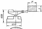
Drilling holes for the flue
P 
After installing the panel, drill holes in the wall for the flue according to the picture. The diameter of the holes is 110 mm, the outlet part of the pipe must have a slope of at least 3% to ensure the flow of condensation water.
^ Hanging the boiler
Attach the boiler to the panel and make sure it is securely installed.
(As shown in the picture on the right).
▲ Note: The following must be ensured around the boiler
minimum free space.
^ To the side surfaces at least 200 mm;
At least 450 mm to the top surface;
At least 300 mm to the bottom surface;
At least 500 mm to the front surface.

^
Flue installation
Restrictive air ring
Refer to the following table when installing all models, whether the air restrictor ring is installed or not.
When installing a flue maximum length pipes cannot exceed 3 meters. When adding a 135° elbow, the pipe length will be reduced by 0.5 m; when adding a 90° elbow, the pipe length will be reduced by 1 m. Two parts of a 90° elbow cannot be installed (except for the elbow between the flue and the exhaust duct).
Attention:
^ 2. The flue connection must be sealed. The material of the sealed connection must be resistant to heat and corrosion.
3. The flue should have a slope of 2~3 degrees behind the wall to ensure that condensation water flows out.
^ 4. Do not use material that promotes condensation to fill the space between the pipe and the hole. The pipe should be easy to remove.
5. The pipe must be connected from the outside. It is forbidden to start the boiler without an installed pipe.
6 
. For distances between the pipe outlet and surrounding walls, see the figure below.
mm
Pipe connection
^ Gas pipe connection
A gas valve must be installed at the connection between the flue pipe and the gas inlet.
The gas duct must be clean. If there are impurities in the gas, a filter must be installed at the gas inlet.
Do not use the flue as an equipment grounding line.
1 
. heating water inlet
2. hot water outlet
3. cold water inlet
4. circulating heating water
5.gas inlet
Wiring diagram


Water supply, replenishment and drainage
Water supply
Unscrew the automatic faucet release valve completely.
Open the heating system valve and the outlet valve at the end of the equipment.
Insert the protective insert and apply power, then start the boiler (Do not open the gas switch).
Start the boiler again and again to restart the circulation pump to remove any residual air.
The water pressure in the heating system will decrease after the air is released .
Close the boiler and turn off the power.
Close the outlet valve at the end of the heating system equipment.
Replenishment
E 
 If, after operating the boiler for some time, the water pressure in the heating system has decreased due to the filling of the pipe system, then in order to prevent abnormal operation boiler due to low pressure water, water should be added to the boiler when the pressure drops below 0.5 bar.
Make sure the outlet valve on the pump is open
Rotate the handle counterclockwise to open the water supply valve.
Check the pressure using the water pressure gauge on the control panel. When the reading reaches 1-1.2 bar, close the water supply valve by turning clockwise.
Z
waterrefill valve
Run the boiler again and again to restart the circulation pump to remove residual air.
D
reducer for safety valve
The water pressure in the heating system will decrease after bleeding . Repeat operations (3), (4), (5) until the pressure is between 1-1.2 bar.
Draining the system
Drying the heating system
Turn off the boiler and disconnect the power supply.
Open the boiler and all valves on the heating system piping.
Open the drain valve and release water from the system, then close the drain valve.
Draining the DHW system
Disconnect the water inlet pipe from the boiler.
Open the heating water pipe valve and release the water.
Attention:
When draining the system, close the boiler and turn off the power supply.
^ The safety valve drain must be connected directly to drainage system, it is not allowed to install valves in the middle of the connecting pipe.
After draining and supplying water is completed, it is necessary to close the drain valve and the water supply valve.
^
Ignition adjustment
Checks before starting work
Check all heating system and domestic hot water connections to ensure there are no water leaks.
Check whether the automatic boiler outlet valve is open.
Make sure that the heating system pressure is between 1-1.2 bar.
Make sure that the gas used matches the gas specified on the nameplate.
Adjustment
▲ ^ Attention: (1) Adjustment must be performed by qualified personnel.
(2) If there are problems with heating and water quality caused by the heating system and domestic hot water supply, please contact an authorized service center.
User operation
in winter
Heating operation
▲ Attention: The heating water outlet temperature can be set within 30~80°C. If you have chosen low-temperature floor heating, the adjustment must be carried out by qualified specialists from an official service center. The heating water outlet temperature can be set within 30~55°C.
^
Turning on water heating for DHW

After setting the temperature, this setting will be saved automatically. The display will return to the current heating system water temperature and the boiler will operate in winter heating mode.
Open the tap, the boiler will automatically switch from heating mode to DHW heating mode. When the boiler is operating in shower water heating mode, close the tap and the boiler will switch from DHW heating to heating mode.
Summer mode (Shower water heating function only)
After setting the temperature, this setting will be saved automatically. The display will return to indicating the current heating system water temperature and the boiler will operate at summer mode heating
Open the tap, the boiler will turn on and operate in DHW mode. Close the tap, the boiler will close and go into standby mode.
(2) Make sure that the power supply and gas supply are normal to ensure defrosting function in cold weather.
(3) When stopping the unit for a long time, close the gas pipe valve, turn off the power, and drain the water from the system.
Security system
The boiler uses a security code indication system. If the boiler enters protection mode, determine the fault according to the following codes:
^ Low water protection
E 1
When the display shows the code shown in the figure on the right, this means that the boiler is entering protection mode due to insufficient water. Switch off the boiler and then supply water according to the water supply method described on page 6. When the water pressure reaches 1-1.2 bar, try turning on the power again and starting the boiler.^ Ignition fault protection or overheating protection
E 2
When the display shows the code shown in the figure on the right, this means that the boiler is entering protection mode due to an ignition fault or the heating system water temperature is rapidly rising and reaches 95°C. Check whether gas is supplied and whether the gas pipe valve is open. Try turning on the power again and press the "○" button, then press the "reset" button to ensure that the boiler operates in normal gas supply mode.^ Heating system sensor fault protection
E 3
due to abnormal operation of the heating system water sensor. First turn off the boiler and then contact qualified personnel authorized by our company.Protection against DHW sensor failure
When the display shows the code shown in the figure on the right, this means that the boiler is entering protection mode and ^
E 4
due to abnormal operation of the G sensorE 4
Sun. First turn off the boiler and then contact qualified personnel authorized by our company.^P E 5
software error
When the display shows the code shown in the figure on the right, it means that a software error has occurred. You just need to press the reset button or restart the boiler. If the control board failure continues, please contact qualified personnel authorized by our company.
^ Exhaust system fault protection
When the display shows the code shown in the figure on the right, this means that the boiler is entering protection mode and
E 6
due to abnormal operation of the exhaust system. This is a temporary situation. When the exhaust system works normally, the boiler will start automatically. If the boiler does not start automatically, contact qualified personnel authorized by our company.^ overheat protection
E 7
When the display shows the code shown in the figure on the right, this means that the boiler is entering a protection mode caused by a rapid increase in the temperature of the heating system to 95°C or a rapid increase DHW temperature up to 80°C. When the temperature drops to a value 6°C less than the set temperature, press the "reset" button to start the boiler.
Maintenance
Check for leaks water pipes and replace the O-ring and easily damaged material.
The system pressure should be 1-1.2 bar, otherwise, supply water according to the water supply method described on page 6.
Check for leaks gas pipes and replace the O-ring and easily damaged material.
Check the burner and main heat exchanger. If necessary, clean the nozzles and remove oxides from the burner. Remove deposits from the main heat exchanger to ensure they do not affect combustion behavior and thermal efficiency.
Provide pressure for the expansion tank to 1 bar.
Check the exhaust pipe for blockages and clean it.
Check the functionality of the water pump and fan.
Attention:
(2) To avoid accidents, users should not remove the boiler and perform maintenance on it. We are not responsible for accidents caused by opening the boiler without our permission.
(3) This boiler must not be used without permission from a qualified authorized service center.
Gas wall mounted Buderus boilers
Models Logamax U042, U044, GB072, GB172. With open and closed camera combustion. Methods of repair and service, adjustment of operating parameters. Maintenance recommendations.  Gas heating boilers Vaillant
Models: floor-standing Atmovit exclusiv, wall-mounted condensing Ecotec plus. Service, maintenance, settings of functional components. Hydraulic diagrams.  Gas wall mounted Ariston boilers
Models Clas, Clas Evo, Genus. Recommendations for repair, maintenance and service. Elimination of errors and malfunctions. Setting and adjustment methods.  Gas boilers Immergaz
Models Eolo Star, Eolo Mini, Nike Star, Nike Mini, Mithos. Repairs and adjustments. Installation, assembly and connection. Operating mode settings and additional equipment.  Boilers Kentatsu Furst
Wall-mounted models Nobby Smart. Condensing Smart Condens. Floor standing Sigma, Kobold. Solid fuel Elegant, Vulkan. Malfunctions and error codes. Description and characteristics.
Weller boilers - Errors and their meaning
Weller wall-mounted double-circuit gas boilers are used for heating systems in rooms up to 230 sq. meters. The modulation burner allows you to achieve the greatest heat transfer when operating at any power, which is the main advantage of the design of this brand. The unit has a closed combustion chamber, as well as an additional condensation module that absorbs heat from the exhaust gases.
The controls are simple and intuitive; almost all adjustments are performed automatically. Wall-mounted Mars models are connected to a standard vertical chimney, and the exhaust of combustion products and air intake from the street are forced through a coaxial chimney.
To maximize the performance of these models, they are equipped with parts and components from renowned European companies. If the automation detects any malfunction, a symbol with an error code is displayed on the display. All models are equipped with separate heat exchangers.
The control unit, in automatic mode, monitors the required pressure in the pipeline and sets the most favorable operating mode, in which gas consumption will be the least. Before use, you must read the instructions. Error codes that appear on the display can help you detect and eliminate the malfunction in a timely manner.
Weller boiler error codes
Error E1– There is insufficient or no water pressure in the circulation system. There is a problem with the hydraulic unit, the rod may be stuck. The flow sensor microswitch is faulty. When there is a power outage, it is recommended to restore the water supply. Increase the pressure to 1.2 bar and start the heating.
Error E2– Triggering of protection against overheating or incorrect ignition. This mode is set in the device at a water temperature of +96 degrees, or due to problems with the ignition system. It is recommended to check the gas supply. Press the “reset” button to reactivate the device.
Error E5– Control board program malfunction. To resolve this, press the “reset” key to restart the unit. If the action is unsuccessful, you should contact the service center.
Error E6– Damage to the heating system sensor. Due to incorrect performance of the function by the sensor, the unit enters protective mode. It is recommended to disconnect the device from the network and replace this component. You can also call customer service.
Error E7– High coolant temperature. The protection cycle is activated in two cases: when the temperature of the heating system rises sharply to 97 degrees or when the temperature of the hot water supply exceeds the limit of 81 degrees. It is necessary to disconnect from the power supply system. If the indicator decreases by six degrees less than recommended, start with the “reset” key.
Error E9– Malfunction of the hot water sensor. Due to improper functioning of the DHW sensor, the unit enters protective mode. It is necessary to disconnect it and replace the hot water supply sensor or contact a service center.
In some cases, when using the unit, it can reduce the temperature by ten or fifteen degrees in the heating system, and sometimes even turn off. In this case, the device must be connected to the electrical network using a stabilizer, so it is this that needs to be checked. Since the stabilizer itself can fail, and a malfunction can only appear when a problem is detected in the energy consumers connected to it.
The Mars 32 gas boiler operates intermittently in DHW mode (practically does not work). He exhibits unusual behavior. When you turn on the tap DHW water heats up almost to boiling water, despite the fact that the sensor is +40 degrees. After 2-3 minutes the boiling water turns off and cold water flows. After 2-3 minutes it turns on and brings the water temperature to boiling water again. And so 4 times. After the last heating to boiling water it displays cold water and will not turn on again. The heating circuit is working normally (I haven’t checked it for a long time - it was summer). After I turn off the boiler, and it stands for about 2 days without power and with the water supply tap closed, it turns on, and again the same troubles. What needs to be done, can something change?
You need to replace the temperature sensor.
I came across a Weller boiler for repairs. A few seconds after turning it on, it displays error E1. Power is not supplied to the pump. The pump is running, the winding and capacitor are ringing. There is no power coming from the board. Has anyone encountered this problem in their practice?
We need to start with the fact that this model polls the coolant flow sensor twice. Before starting the pump, it must be open, and then closed. If any of the conditions are not met, error E1.
Boiler Weller Mars 26. Gives error E02, ignition error. The flame lights up and goes out. It works fine with the combustion chamber cover removed. As soon as you close the lid, it goes out. The chimney is clean, the fan, pneumatic relay, gas valve, ignition electrode, and ignition unit have been replaced. Nothing helped. Electrical network fine. Who can help?
For turbocharged models, it should be the other way around. I would venture to guess that there is either an excess or a severe lack of air.
Weller mars 26 boiler. It cycles a lot during operation. For example, the heating costs 40 degrees, it turns on, quickly heats up to 38-40 degrees, the burner goes out, the temperature quickly drops to about 32-33, and the burner starts again and so on in a circle. If I increase the temperature, for example to 48, the unit heats up for a long time (on the display the same temperature is around 49-50 or even drops by a degree). When all the water in the batteries heats up, the burner goes out, and then the temperature slowly drops. The burner turns on, and now it begins to clock again. What thoughts? Poor flow in the heating system? Does it have a filter? Gas not regulated? And is there any way to increase the delta?
It looks like a typical malfunction of the electronic board, when the unit stops modulating the flame and heats at maximum.
Mars 26 boiler. The boiler does not start. It doesn’t write anything (it shows two zeros), it doesn’t respond to resets, and the power button turns off the display. The unit is double-circuit, the water circuit is closed with two plugs. Gas is normal. The pressure in the system is 1.5-2 atm. The boiler turned off because there were problems with the gas supply, the pressure dropped to 0, but it did not show any errors. Last time there was a similar situation: the light was turned off for half a day, the pressure dropped, it did not turn on, it gave an error (low pressure). I raised the pressure, but it still wouldn't turn on. It rumbles twice and then stands still. Somehow it happened (I pumped in more than 2 atm pressure and then decided to bleed it down a little to 1.5) that the next time I turned on the electric plug, the unit immediately started turning the pump and then turned on. But this time nothing happened. What could it be?
There was a similar problem. The boiler gave error E6, apparently it lacks draft or the exhaust is bad, I pulled out the tubes from the sensor to the fan. I stuck one tube onto the fan and the piezo clicked. I made a reset, the device was quickly tested, started the fan and lit the burner. I didn’t plug in the second tube, I waited about two hours until the system and chimney warmed up well internal air. Turned it off, then installed all the tubes as they were, turned it on, and it started up fine.
Please help me with the problem: the mars 32 OC boiler does not turn on, it shows error E1 (lack of pressure in the heating system). The pressure is normal, above 1 bar, the pump does not start, a faint click is heard. The red LED on the DHW flow sensor is on, although I don’t use the DHW, the output there is muted, and through the input I only recharge the unit.
First, look at the DHW flow sensor, clean or replace the bronze screw-in “cartridge”. Then look at the heating flow sensor. Most likely, it is filled with water. It is necessary to change the oil seal and dry the microswitch.
___________________________________________________________________________________________
___________________________________________________________________________________________
Borino, ZhMZ, Siberia, Alfa Kalor, Termotechnik.
Adjustment gas automation Eurosit 630. Replacement of thermocouple and maintenance of pilot burner.
Models Luna, Luna 3 Comfort, Luna Duo Tec (F/Fi). Double-circuit, turbocharged. Recommendations for eliminating errors and malfunctions. Settings and adjustment of operating modes.
Models ZWC, ZSA, ZSC, ZWR, Gaz 5000, Gaz 3000 W ZW, WBN 6000.
Wall-mounted, double-circuit. Repairs, adjustments and malfunctions. Settings for functions and modes.
Deluxe Coaxial, Deluxe Plus, GA models. Errors and problems.
Work with remote control Xital. System control. Adjustment of work by temperature and pressure.
Repair of Logano G124, G125, G215, G234, G334 models. Breakdowns and malfunctions. Operation with Logomatic control system and boiler indirect heating. Modes and functions.
Models Turbotec Atmotec pro/plus VU/VUW INT. Components and operating functions. Programs for adjustment. Gas system. Installation and assembly. Maintenance and prevention.
Are Chinese heating boilers really low-quality equipment by default? The majority of buyers in the Russian Federation have a strong opinion that this is not without reason. But this stereotype can be destroyed by considering the technical characteristics of Weller gas heating boilers.
The main difference between Weller brand products is their undoubted quality, reliability and ease of use. One of the best proof of the model’s popularity is that the company’s thermal generators are popular not only in the Russian Federation, but also among more demanding European buyers.
Chinese brand Weller
Initially, Weller was presented as an Italian manufacturer. Over time, products began to be produced in China. Today Weller is owned by a Chinese company.Surprisingly, the manufacturer managed to do what other concerns were unable to do - maintain European quality and technical characteristics, making the cost of production lower and, accordingly, more attractive to the consumer.
The produced models are focused on apartment heating of the house. The consumer is offered mounted models of a dual-circuit type with a closed combustion chamber.
Mounted boilers in demand on the market
If we look at the statistics, it becomes clear that for the average consumer the most attractive choice is mounted models heating equipment. The number of sales of units that can be hung on the wall significantly exceeds the sales of boilers that require installation on the floor. This is especially obvious in the case of apartment owners in a multi-storey building who want to install autonomous heating.What explains the popularity of the boiler models presented by Weller? 
Judging by customer reviews, the only weak point of the Weller thermal station is the vulnerability of the control unit to voltage surges in the network. You can ensure safety by installing a UPS.
Main principles of installation and use
When developing this model, the manufacturer primarily focused on producing a boiler that would be easy to install and maintain. As a result, installation does not require compliance special conditions and connecting additional equipment is done quite quickly.No adjustment or tuning of the boiler is required after installation. The control unit automatically monitors the pressure in the pipeline and selects the optimal option for operation, such that the natural gas consumption is minimal.

The operation of the Weller boiler depends on some factors that will need to be taken into account before installation:
- Compliance with the manufacturer's recommendations and requirements. For example, a supply and exhaust adapter is installed in the smoke removal system, which monitors the presence of draft in the chimney. Irregularities during installation coaxial pipe lead to failure of the automation to turn on the boiler.
- Connection to the electrical network and installation of temperature sensors must be carried out by a qualified specialist.

Ease of operation is achieved thanks to the system of “intelligent” control of the boiler operation. Installed controller independently makes decisions about changing the operating mode depending on external and internal factors, making the operation of the device as comfortable and economically profitable as possible.
Get rid of the prejudices that China is of poor quality
The example of Weller equipment proves that China is not always bad, and sometimes even very good. Full automation of the heating process, adaptation to domestic conditions, no need for self-adjustment pressure, smart automation - all these functions put the company’s models on a par with their European counterparts.The boilers were designed for apartment heating and can be installed in small rooms, without the need to use a separate boiler room for these purposes. A good choice for residents of an apartment building!
All work described in this document must be carried out technical specialists
authorized service centers WELLER. Keep technical documentation handy. For execution
The described work may require the information contained in this manual.
2. Description of the device.
2.1. general description devices.
Double-circuit wall-mounted gas boiler WELLER MARS with a closed combustion chamber and separate
plate heat exchanger designed for heating and hot water supply. Boilers are supplied
power 24 and 30 kW. The devices run on natural gas (G20) as standard.
2.2. Main technical parameters
Model
Mars 26
Mars 32
Unit change
Nominal heat input 26
32
kW
Rated thermal power 24
29,5
kW
Heating system temperature range 30~80 30~80 °C
Heating system operating pressure 0.5~1.5 0.5~1.5
bar
Maximum heating system pressure 3 3
bar
Expansion tank capacity 6
8
l
Set pressure of expansion tank 1
1 bar
Hot water temperature adjustment 30~60 30~60 °C
Maximum tap water pressure 6 6 bar
Minimum tap water pressure 0.2 0.2
bar
△t=25°C, possibility of obtaining hot water
13
15
l/min
△t=35°C, possibility of obtaining hot water 9.5 10.7
l/min
Voltage/frequency 220~230/50 220~230/50
V/Hz
Maximum power consumption 110
150
W
Insulation class I
I
compound
Connecting water pipes for heating
G3/4 G3/4
Trubnoe
Gas inlet
G3/4 G3/4
Connecting water pipes for shower
G1/2 G1/2
Air inlet/outlet
60/100 60/100 mm
Nominal pressure for natural gas 0.02 0.02
bar
Nominal pressure for LPG 0.03
0,03
bar
Net weight 38.5
39
kg
Overall dimensions: L×W×H 740×410×328
740×410×328
mm
3

2.3. Design
Rice. 2.1.
4


Rice. 2.2.
5


Rice. 2.3.
6

Rice. 2.4.
7
2.4. Specification
No.
Name
Qty
1
Left bracket 1
2
Phillips screw 8
3
Hanging strip for attaching the boiler to the wall 1
4
Top bracket 1
5
Upper bracket for expansion tank 1
6
Expansion tank 1
7
Right bracket 1
8
Side bracket 2
9
Burner
1
10
Ignition and ionization electrode 1
11
Sealing ring for gas inlet pipe 6
12
Gas supply pipe to burner 1
13
Gas valve 1
14
Right hook
1
15
Rivet
4
16
Left hook
1
17
casing
1
18
Rating plate
1
19
Screw
2
20
Dustproof hood 3/4" 3
21
Safety plate
1
22
screw
2
23
Screw for fastening the casing 2
24
Washer
2
25
Phillips screw 2
26
Protective gasket for power wires 1
27
Bottom tray
1
28
Lower bracket for expansion tank 1
29
Connection nut with expansion tank 1
30
Heating system outlet pipe 1
31
Main heat exchanger 1
32
Temperature limiter control 1
33
Phillips screw 2
34
Heating system inlet pipe 1
35
Nut 3/4" 2
36
Outlet pipe from pump 1
37
Rubber ring in/out. Pump 2
38
Washer for water pressure gauge 1
39
Water pressure gauge 1
40
Water outlet clamp from water pump 1
41
Water pump 1
42
Pump water inlet pipe clamp
1
43
Washer for pump mounting
2
44
Phillips screw
2
45
Washer
2
46
Phillips screw
2
47
Water inlet valve
1
48
Flow sensor
1