The popularity of laminate floors is easy to explain - they are beautiful, durable, durable and easy to install. However, not everything is as good as it could be. Laminate, although it may be similar to wood in texture and color, still does not have sufficient heat capacity and may feel cold when moving on it. Therefore, many owners of apartments and houses, especially those living on the first floors, are seriously concerned about underfloor heating. Infrared heated floors under laminate can be the best solution to the problem of cold floors.
Infrared heated floors resemble in appearance a thick film with black stripes on it. However, heat mats are only part of a complex electrical system that allows you to heat the base in an apartment.

In this case, floor heating occurs due to infrared radiation, which appears due to the carbon paste located between the sheets of transparent film. It is applied in parallel lines and looks like those same black stripes. The emitted waves have a length of 5-20 microns. System, thanks additional elements, is connected to the electrical network, where the current conductor is a connection of copper and silver.

On a note! Carbon has a fairly high thermal conductivity, due to which energy consumption can be significantly reduced. That is why infrared floors can be called a fairly economical heating option for floors. At least the costs public utilities in this case, much lower than when using conventional electric or water floors.

The main part of the infrared heating system is precisely those striped film heaters. They are sold in rolls and can have a width of 50 cm or 100 cm. Cutting them is convenient, since there is a cutting line approximately every 25 cm, which allows you to buy exactly as much film as you need to install a heating system in a particular room. The film is sold by the meter.
Attention! It is strictly prohibited to cut the film in a place not marked with a special marking! This will damage the canvas and it will not work.

The power of infrared films is 150, 200 or 440 W/m2. These indicators will be useful during calculations regarding the arrangement of a heated floor system, to identify the load on electrical system Houses. For laminate, it is optimal to use mats with a power of 150 W/m2. They will allow you to heat the floors to a maximum of 40-45 degrees, and a higher temperature is not necessary. Otherwise, it will be unpleasant to walk on the floors, and higher values will have a negative effect on the surface itself. Optimal temperature for legs - about 27 degrees.

Also, a heated floor system with infrared heating necessarily includes:
- thermostat;
- special clips or clamps;
- wires for connecting the system.
The infrared floor system is highly reliable, since the individual elements are connected in parallel - if there is a problem in one of the elements, the rest will continue to work.

Is it possible to install infrared heated floors under laminate?
The heat capacity of laminate is higher than tiles, and its thermal conductivity is lower compared to the same material. They don't like laminate floors high temperatures, and therefore should not heat up excessively. If you install a water or electric heating system under the laminate, you will have to ensure a constant increase in the temperature of the heater, which will negatively affect both the material itself and the amount of utility bills.
Laminate does not like sudden temperature changes, which cannot be avoided when installing any other heating system. In case of negative temperature effects, there is a risk of cracks and cracks appearing in the material, and the floor may begin to creak. Neither a water nor an electric floor will provide optimal heating of the surface in terms of heating level and uniformity.

Due to their small thickness, the lamellas heat up quickly, because IR rays will spread quite quickly throughout the material. Also, if the floors are made correctly, the radiation will not go towards the rough base on which the film lies, which means there will be no heat leakage. Thus, IR floors are the best option for heating laminate floors.

Advantages of using film heating
IR floor heating has many advantages that make it one of the best options for heating laminated floors:
- optimal and uniform temperature distribution over the entire floor area;
- economy;
- the optimal floor temperature level is within 45 degrees;
- rapid heating of the surface;
- ease of installation and repair;
- there is no need to install a screed, since the floor covering can be laid on thermal mats;
- long period of uninterrupted operation.

The main disadvantage of such floors is quite high cost of equipment and materials, but the investment will be fully justified if you take into account all the advantages of the system.
Which laminate to choose for IR heated floors?
Before you finally decide on the infrared type of floor heating, you need to study information about which laminate can be laid on top of this type of heaters without harm to itself. Suitable material must have a special marking in the form of a “snake”. It is this designation that informs the future owner of a warm laminated floor that the laminate is suitable for installing a heating system.

IR heated floor under laminate - subtleties of technology
Installation of an infrared floor system, although simple, requires attention and has certain features. Still, the work is carried out using the home’s power supply system, so mistakes should not be made here. Otherwise, the floors will either not work or simply become dangerous for the home owner.

Even before installation begins, a complete and accurate floor laying diagram is drawn up, on which the IR mats themselves and all system control elements are indicated. The installation locations of thermostats, temperature sensors and other equipment must also be marked. It is important to remember that all the wires that will come from the heating system are connected directly to the thermostat.
The thermostat is usually installed on the wall, and in order to hide all the wires, it is recommended to cut a narrow groove into it, into which communications will be laid. Thus, they will not be conspicuous, because after laying the wires the cavity is sealed. In this case, the wires must be placed in a corrugated tube.

On a note! If you don’t want to trench the walls, then all communications can be hidden in a plastic gutter mounted on the wall.
Also, first on paper, and then on the floor itself, a diagram of the location of all infrared films is drawn. This procedure, in addition to convenience during subsequent installation, will also help to accurately calculate the consumption of all materials - wires, films, etc. The connection points of all wires are also marked on the diagram.
Nuances when working with IR film that should be taken into account before installation:
- the film is cut only along clearly marked lines;
- that was fewer places connections of individual sections, the film should be rolled out along the long wall of the room;
- there must be a gap between the wall and the first line of the film - its width cannot be less than 25 cm;
- designations of the places where the furniture will be placed are immediately entered into the diagram (bedside tables, cabinets, sofas, etc.) - the film is not placed under them, which will reduce material consumption, and in the future the floor in this place will not overheat, which means the system will not burn out;
- each strip of IR film is placed at a distance of 5 cm from the adjacent one;
- the neutral and phase wires should not intersect when connecting, so they are connected only on opposite sides of the film;
- the temperature sensor should be located in the coolest place in the room so that it is in the middle of one IR element;
- the length of one IR strip cannot be more than 8 m;
- a suitable place for the thermostat is 15 cm from the floor level;
- Individual strips of film cannot be laid overlapping or on top of each other.

On a note! There is no need to worry that the floor heating will be insufficient if the film does not lie on the entire surface of the floor. The fact is that for optimal heating it is enough for the heaters to cover only 40-60% of the base of the room.
Preparing the foundation
The subfloor must be smooth and clean - litter and large debris are not allowed, it is also important to remove pebbles, sand, and dust. It is recommended to check the floor for strength, repair cracks and gaps, and level them to acceptable parameters.
Advice! To concrete base less dusty, it is recommended to treat it with a primer mixture, although this procedure is optional.
Also, thermal insulation material should be laid on the subfloors. It is recommended to use foil. The shiny side should be up. The strips are laid end to end. The thickness of the foil material should be about 2-3 mm. It is most convenient to secure the material using double-sided tape, and the gaps between the individual strips can be closed regular tape. Then small recesses will be cut out of the material into which terminals, wires and other communications are placed. Then the base for the capricious laminate will be optimally smooth. It is also recommended to lay a layer of waterproofing material on the base of the floor.

Materials and tools
What may be needed to install an IR floor system? These may be the following tools and materials:
- directly the IR heating film itself;
- heat reflector;
- temperature sensor and temperature controller;
- regular and double-sided tape;
- electric wires;
- clamps and material for wire insulation;
- waterproofing material (for example, polyethylene film);
- knife, scissors, pencil, ruler, tape measure.

At the beginning of the article, a description of IR film was given, but in fact, it is not only carbon.
Table. Types of heating film.
| View | Characteristic |
|---|---|
| The optimal option for IR film used for arranging a floor heating system. Its description was given in the article above. The heater consists of two layers of film, between which there are strips of carbon elements, due to which heating occurs. The material is environmentally friendly, efficient, reliable, economical, does not cause negative impact on human health. Service life - decades. Heat transfer is 97%. The main producing countries of such flooring are the Netherlands and South Korea. |
| Such a floor is also created from two layers of polyurethane film, between which a conductor made of copper and aluminum is laid. Installation of such a system is somewhat more complicated due to the lack of a grounding wire. The material can also be used under laminate (such heating systems cannot be used under ceramic tiles and porcelain stoneware). The system is functional, distributes heat well, and is suitable for use in Russian climate conditions. |


There is also another type of IR film. It appeared relatively recently, but has already begun to be used in great demand. These are films with a continuous carbon coating. Unlike standard carbon IR film, this material practically does not fail when damaged - that is, the floors will always be warm.
On a note! If you damage one or several strips of a regular infrared floor, then it will not warm up at their location. However, when using a film with a continuous strip of carbon fiber, the floor will warm up just as evenly, even if it has been damaged. It’s just that in the place of the cut or break the material will be a little cooler, but it will continue to heat.

Film floor installation
Let's take a closer look at the process of installing IR film under laminate.
Table. Do-it-yourself installation of infrared floors - step-by-step instructions.
| Steps, photo | Description of actions |
|---|---|
| Measurements are taken from the entire floor in the room where installation will take place. It is also recommended to check the evenness of the rough base using a level. |
| A place is selected on the wall where the thermostat will be located. |
| The surface of the subfloor is covered with heat-reflecting material. Strips of material are laid joint to joint with the shiny surface facing up. Izolon can be used as a heat reflector. |
| The heat-reflecting layer is fixed to the base using tape or a stapler. |
| The joints of the heat reflector are taped with tape. |
| The IR film is placed on the heat reflector so that the copper strip is at the bottom. |
| The film is being cut. In this case, all cuts are made with scissors along strictly marked lines. |
| The film strips are laid in such a way that there is a distance of at least 25 cm between them and the wall, and 5 cm between individual strips. Also, the film does not spread where large-sized furniture will be placed, so that the floors do not overheat in the future. |
| The places where the copper busbar was cut must be insulated with strips of bitumen insulation. It should cover the silver contacts along the entire cut. |
| Where the wires will be connected, contact clamps are installed on strips of copper. They are positioned in such a way that one part of them is inside the IR film, and the second is outside. |
| The terminal is clamped with pliers. |
| The film strips are fixed on the surface of the heat reflector and among themselves using tape so that the material does not move during operation. |
| The wires are inserted into the terminal and secured with pliers. |
| All places where wires are connected to the IR film are insulated. Two pieces of insulating material are used for each contact point. One is fixed outside the film, the other is closed inner side films. It is important to ensure that the silver contacts at the edges of the film are also insulated. |
| The temperature sensor is mounted under the IR film on the black graphite strip of the heater and fixed with a piece of insulation. |
| For the sensor, a small cut is made in the heat-insulating layer using a knife. The sensor must fit into it when the film is lowered. |
| Cutouts on the heat reflector are also made for contacts and wires. |
| All wires in the recesses are sealed with tape. |
| A temperature controller is installed on the wall surface in a selected location, to which the wires are connected according to the instructions and connection diagram attached to the thermostat. |
| The system is being tested. The heating system turns on, the floor temperature is set to a value not exceeding 30 degrees. The heating of all strips of thermal film is checked. |
| IR mats are covered with polyethylene film for additional protection. The installation of the heating system is complete. |
| Laying in progress finishing coating for the floor. The laminate is laid using conventional technology on top of the film. The work is carried out carefully so as not to damage the thermal film. |


Prices for IR film heated floors
infrared heated floor
Video - Installation of heated floors under laminate
Features of installation work
And finally, a few tips for installing an infrared heating system:
- humidity in the room where work is carried out should be no more than 60%;
- installation of IR floors is carried out at a temperature of 0 degrees and above;
- Thermal film, even for testing, must be connected to the network only in an unrolled state - it cannot be connected in a roll;
- if the film was damaged in the area where the graphite (black) layer lay, then the place of damage must be isolated on both sides;
- the temperature sensor must be connected so that, if necessary, it can be easily replaced;
- If there is a flood in the apartment, then it is important to immediately turn off the floors and not use them until they are dry.

If the infrared floor heating system was connected correctly, it will last for decades. It is important to carry out all work carefully and carefully - only in this case can you get the desired result!
Since his appearance on earth, man has strived to create comfortable conditions accommodation: dry, warm and beautiful home. Modern apartments and the houses almost fully correspond to these wishes. Only systems cause some discomfort central heating with a radiator type of heat transfer: the floor is always cool, the warmest space is under the ceiling, and in the house (apartment) there is a constant upward flow of air near the radiators, causing drafts. Laying infrared heated floors under laminate solves this problem.
Operating principle and design features
In nature, heat is transferred in two ways:
- Convection, when heat is transferred directly from body to body by air;
- Rays (this is how the Earth receives heat from the Sun). A physical principle is involved here, based on the ability of bodies heated above 60 degrees Celsius to emit waves with a length of 0.75-100 microns, which are of an electromagnetic nature. The basis of IR emitters is the ability of bodies to emit waves in a given range (from 5.6 to 100 microns).
An infrared “warm floor” consists of a base layer, conductive strips (copper and silver), a carbon emitter and a laminating film. Under the influence of current, carbon paste begins to emit rays, which, upon reaching a dense body, begin to heat it.
In the case of heated floors, heating is carried out directly from the laminate, which already warms the room by convection. Since the rays have different lengths, some of them pass through the floor and heat the surrounding objects. That is why it is prohibited to place furniture above heating elements to avoid overheating of the IR film.
Film heaters are produced with a power from 150 to 440 W/m2 (for laminate, the maximum power should not exceed 150 W/m2). Standard width films can be of 4 sizes - 50, 60, 80 and 100 cm. Any length - produced in rolls. However, at certain intervals, special strips are provided along which the film is cut to any length - increments of 20 or 25 cm.
Advantages and disadvantages of IR heated floors
Infrared film heated floors under laminate have both supporters and opponents. This is due to the fact that this heating system has many positive and negative qualities. That being said, the strengths are truly impressive.
- The heat transfer features allow you to heat only those surfaces where a person is present: walkways, workstations and rest areas. In this case, energy is not wasted on heating the bottom of the furniture, which leads to a reduction of up to 20-30% in electrical energy consumption and, consequently, in family finances. Another advantage of this approach to placing IR film is its savings.
- Low cost of materials and installation work when assembling infrared floor heating. A clarification is needed here. The price of a film heating kit is very high when compared with other types of “warm floors”. It starts from 2,000 rubles. for components (includes temperature sensor, temperature regulator, electrical wires, contacts, bitumen tape), plus from 650 rubles. for every m 2 of IR film. However, the significant costs of purchasing materials are offset by the low cost of installation work.
- The infrared heating system is not afraid of sub-zero temperatures— manufacturers allow its operation at temperatures down to –70 o C. This means that during prolonged exposure to unheated rooms in winter, the system does not lose its functionality. This property is difficult to overestimate when using IR film in country houses where there is no permanent habitation, and in summer cottages.
- There are no restrictions on installation either by type of building or type of premises. The system can be installed in individual houses and apartments, living room, children's room, kitchen, bathroom, etc. In this case, there is no risk of flooding neighbors as with a water “warm field”.
- Easy installation and dismantling. Connecting current-carrying elements and connecting to electricity does not require work skills, but attentiveness and pedantry, which allows you to complete the entire cycle of work with your own hands. At the same time, installation is carried out very quickly.
- The spectrum of infrared radiation of carbon elements is completely identical to solar heat.
- No repair required. The failure of one or more emitting strips does not affect the operation of the film as a whole - the connection to the power supply is parallel. If there is a need to replace the film completely, then no problems are foreseen here either - it can be easily dismantled.
- Uniform heating of the room is achieved. At the same time, what is important is that warm layers of air are located at the bottom of the room, and not under the ceiling, as when heating with batteries. This heat distribution makes it possible in practice to implement one of optimal conditions human life - “keep your feet warm and your head cold.”
- The warm-feeling floor allows you to walk barefoot, which is good for health, and also to let small children down on it without fear of them getting cold under the influence of internal drafts.
- The long service life of film floors is ensured even with uninterrupted operation. They do not require any maintenance, technical or otherwise.
- There are no invection and convection movements of air flows inside the room, which gives an unexpected result: there are no internal drafts; practically no dust rises into the air (most of it remains in the places where it forms), which is important for allergy sufferers (they don’t get sick) and housewives (less cleaning work).
So that this article does not look like an advertisement for infrared heating systems, we will also present its disadvantages, which will allow the consumer to get full information about this heating method. There are few of them, but they can significantly sway the desire to install infrared heated floors under laminate in an apartment or house.
1. Despite the high efficiency of carbon emitters (more than 80%), the energy consumption of the system is very high, which will cost the owners a tidy sum when paying for electricity. Let's show this with a conditional example.
| Total area of the apartment, m2 | 78 |
|---|---|
| Area of laid film, m2 | 51 |
| Power consumption per m2, W/hour | 200 |
| Power utilization factor (when heated to the required temperature, the system turns off) | 0.6 |
| Electricity consumption per apartment per heating hour, kW/hour (200/1000x0.6x51) | 6.12 |
| Electricity consumption per apartment per day, kW/hour | 146.88 |
| Monthly electricity consumption for heating, kW/hour | 4406.4 |
| Cost of 1 kW/hour, rub. daily rate (3/4) | 3.61 |
| Cost of 1 kW/hour, rub. night rate (1/4) | 2.09 |
| Heating costs per month, rub. | 15124.97 |
| Heating costs per year, rub. | 90749.82 |
As we can see, for people with incomes slightly below the average level, such heating is financially unbearable. Therefore, we can only talk about additional source heating, for example, the floor in a bathroom or toilet, which is turned on when visiting them (the floor surface warms up within ten seconds).
2. Carbon emitters operate on a 220 W network, which leads to several types of risks:
- electric shock;
- short circuit when moisture gets on the film;
- fire.
Judging by the reviews on the forums, the presence of grounding and automatic shutdown in case of a short circuit do not always provide a 100% guarantee safe work films.
3.Dependence on power supply. With frequent shutdowns, the effect of infrared heating is sharply reduced.
4. It will not be possible to change the arrangement of furniture or add something to the room without changing the layout of the film heaters. You will have to dismantle the floor covering and lay down the film according to the new layout.
The given strengths and weaknesses of IR heaters allow you to weigh the pros and cons and make your own choice. Let us note that with the growing well-being of the population, the popularity of the systems will only grow - they have many tempting advantages.
Which laminate is better to use in conjunction with infrared heated floors?
The effect of installing IR film can be reduced or even eliminated by the wrong choice of laminate for finishing floor. Slats that do not match the type of heater can become deformed and release formaldehyde in amounts exceeding sanitary standards, poor conduction of heat, etc.
You can avoid the problems listed above by knowing which laminate for infrared heated floors and how to choose. It must meet the following requirements:
- Have a locking connection. The use of glue to connect the panels creates a rigid, continuous floor covering that breaks during sudden temperature fluctuations, which is what happens when the film is plugged into the network;
- Good conduction of heat. Laminate manufacturers evaluate this ability of lamellas by the coefficient of thermal resistance. The smaller it is, the better the heat from the heater is transferred to the heated room. For infrared “warm floor” it should be in the range of 0.05-0.10 m 2 x °K/W;
- Have a thickness of 8 to 9 mm. In thin panels, the locking joint is destroyed during the process of expansion and contraction due to temperature changes, thick panels conduct heat poorly - they have a low thermal conductivity coefficient;
- Do not release formaldehyde when heated to 27-30°C. When purchasing a laminate, you must take this factor into account and buy flooring of class E0 or E1;
- Have wear resistance of at least class 3. The higher the indicator, the stronger the floor.
Attention: IR heaters can be installed not only in combination with a wooden (pressed wood fiber) laminate, but also under vinyl - the manufacturer allows it.
Information about the requirements considered can be obtained from the pictograms printed on the inserts (see photo) and digital symbols.
Installation instructions for infrared heated floors
The installation technology for infrared floor heating consists of several independent species work performed in strict order:
- planning the power and arrangement of heating elements;
- surface preparation;
- installation work on assembling the heating system;
- connection to electrical networks;
- thermostat connection.
Planning and rules for placing lanes
Before starting installation work, you need to plan the future heating system in detail:
- reflect the location of the furniture;
- calculate the length and width of each strip of film;
- calculate the power of the system (you can contact the sellers for advice);
- draw with a pencil or pen a diagram of the placement of elements emitting IR rays, indicate the location of the temperature sensor, determine the order of connecting the wiring so that they do not cross (you can connect on one side or on both).
In this case, you need to take into account some requirements and observe the existing nuances:
- The length of the film is cut every 20 or 25 cm;
- heating elements must be placed along the room - the number of network connection points is reduced;
- IR film should be located from the walls at a distance of 0.25-0.30 m;
- exclude the placement of the film under the furniture - the heating elements overheat and the carbon strips burn out;
- There should be 5 cm between rows of film;
- the temperature sensor is located in the middle of the film strip, but with the condition that its standard wiring is sufficient to reach the thermostat.
The instructions on how to lay infrared heated floors under laminate do not contain the important stage works: purchasing the necessary materials, tools and equipment. Therefore, the next step on the path to a warm floor is a trip to a hardware store.
Materials and tools
To assemble infrared floor heating you need to buy:
Firstly, a set of film heated floors, which includes:
- IR film (sold in widths of 0.5 m, 0.6 m, 0.8 m, 1.0 m);
- electric wires;
- fastening clips for fixing infrared film;
- clip contacts;
- bitumen tape.
- temperature sensor with wire;
- thermostat;
- foil backing;
- polyethylene film for waterproofing the heating system from leakage of water spilled on the floor;
- electrical tape;
- household or masking tape;
- scissors (construction knife);
- pliers;
- roulette;
- ballpoint pen or pencil.
Preparation
The thin film of the heating element reacts very sensitively to the slightest unevenness of the subfloor - it is easily damaged. Therefore, the floor screed must have a flat, dry surface (you can see how to perform floor screed work in the materials “” and “”).
Before laying the film:
- the surface of the screed is swept and vacuumed;
- a foil backing (3 mm thick) is laid with the reflective side up so as not to heat the base of the floor;
- the joints of the substrate are glued with foil (painting is allowed) tape;
- a recess for the temperature sensor is cut out in the substrate (a similar operation for the terminals and wires is carried out after connecting the system to the thermostat unit).
Installation
1. In accordance with the developed installation diagram, the installation location of the thermostat unit is marked on the wall. Channels for wiring are installed to it. One to the electric power supply system (panel with automatic switches), the second - down to the floor, for wires from the film heater.
A thermostat is attached to the wall and wires are connected to it, after which the grooves are sealed gypsum putty(electricity can also be supplied along the wall surface in plastic channels).
2. The film is cut with scissors strictly along the designated stripes. Here you need to be very careful and careful - accidental damage to conductive or radiating strips leads to rejection of the damaged area.
3. Unused film contacts are insulated with bitumen tape (included in the kit). The insulation must completely cover the silver contact exposed after cutting the film.
4. Heating elements are placed around the room in accordance with the plan with the copper strip down, after which they are attached to each other and to the substrate with household or masking tape.
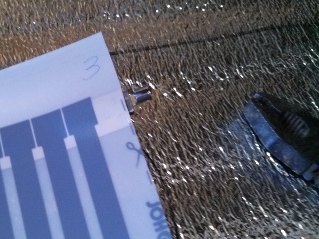
5. Terminals are installed on the conductive strip of the film. To do this, one part of the contact clip is inserted inside the film (the manufacturer provides a technological cut), the second remains outside, always from below. After this, the clip is crimped.
6. The lead wires are stripped and inserted into the terminal. Clamping is done using pliers.
7. The terminal is insulated with bitumen tape- its strips are glued on top and bottom, after which they are tightly connected. To ensure complete sealing of the connecting unit, any air bubbles remaining between the strips of tape are removed.
The advantage of bitumen insulation is that when it is first connected to the electrical network, it heats up and, taking the shape of the protected connection, seals it as much as possible.
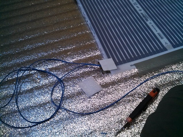
8. A temperature sensor is attached to the IR film. Before installing it, the unconnected end of the film is freed from the tape with which it is attached to the substrate and rolled up so that the reverse side is accessible.
The meter is attached to it on a black carbon strip (emitter) with bitumen tape, exactly above the cutout in the substrate. Along the entire length of the standard wire from the temperature sensor, a cut is made in the substrate into which the wire is recessed. The film is returned to its place and re-attached to the foil with tape.
9. Recesses are cut in the substrate for wires and terminals. The laid wires are fixed with masking tape (elements of the heating system are not allowed to protrude above the surface of the substrate).
Network connection
The wires from the film are connected through special terminals to the thermostat unit. The system is powered without fail through an automatic device - a special protective device (RCD). If you do not know how to calculate its power, you need to seek help from a specialist. You should avoid twisting the ends of the wires - overheating of the connection point is possible due to poor contact.
Attention: connecting the IR film to a power outlet is strictly prohibited.
Grounding the power supply system will help ensure complete safety.
Connecting the thermostat
Self-regulation of the system occurs using a temperature sensor and thermostat. The sensor is connected to the unit with a standard wire, which must not be extended - the signal strength will be distorted. The procedure and connection diagram are located in the instructions supplied with the thermostat unit (they differ from one manufacturer to another).
Upon completion of installation, a test run is carried out. If everything is done correctly, you can begin laying the laminate.
The nuances of subsequent installation of laminate
Laying laminate flooring on an infrared heated floor is carried out only after work has been carried out to protect the heating system from water spilled on the floor (if water gets on the infrared film, it can cause short circuit). To do this, a polyethylene film is spread over the top of the substrate and heating elements, overlapping, overlapping the walls.
The connecting seams are carefully sealed with tape. After this, you can install the laminate. For those who plan to carry out this work themselves, we recommend that you familiarize yourself with the work “”
Conclusion
Infrared “warm floor” is gaining popularity due to the many positive characteristics. But significant electricity costs are holding back its sales. Installation is simple, but requires careful fulfillment of all requirements. The most important of them:
- very smooth screed surface;
- the substrate must be foil;
- all open contacts are isolated;
- terminals, electrical wires and temperature meter must be recessed into the substrate;
- connection to the network is carried out only through an RCD;
- A waterproofing film made of polyethylene is laid over the heating elements.
You need to select a laminate according to the pictograms and inscriptions - they are on the insert.
Laminate flooring is becoming more and more popular every year. Today, manufacturers offer many of the most different models With different characteristics, which are suitable for installation in all possible operating conditions. It is known that wood is a relatively poor conductor of heat, so wooden coverings are often not laid indoors if a heated floor system is to be installed.
At the same time, not so long ago, manufacturing companies began to offer consumers special models that can be used in conjunction with heating elements built into the floor. When purchasing such models, you will see a special mark on the packaging or sticker, which will indicate the possibility of using them together with heated floors. Such a mark is mandatory, so in the process of selecting a model, you need to pay attention to this circumstance.
Experts note the possibility of using heated floors and laminate together if the floor covering is not too thick. In other words, if you plan to install heated floors and laminated floors, then preference should be given to the thinnest models that will transmit heat better (the best option is a thickness of 7-8 mm).

There are several types of heated floors, but when installing laminated flooring in a room, it is recommended to give preference infrared film. Infrared heated floors under laminate have high level heat transfer, and the laminated panels will not heat up too much, so there will be no negative impact on the structure of the floor.
In addition, infrared film allows for maximum uniform heating of the room, which is very important for creating a favorable microclimate in the room.

Infrared heated floors are a type of electric heated floors, but their operation is designed for economical power consumption. If any section of the infrared film is damaged, the heating will continue to operate as usual, and only the damaged section will turn off.
Also among the advantages of choosing infrared heated floors for laminate flooring are:
- Installing heating elements will not take more than an hour and everything can be done with your own hands;
- No device required cement screed, use of adhesives and other compounds;
- The operation of the heated floor can begin immediately after the laminated floor has been laid;
- During operation, the infrared film will not emit any harmful substances;
- The average service life under normal operating conditions is several decades;
- The film does not require any maintenance;
- There is no need to buy or configure additional devices and units for the film to work;
- It is possible to select a specific heating mode for a specific situation.

Despite the significant initial costs, an infrared heated floor system pays for itself within several years of use. Naturally, initially it will be cheaper to lay a cable or water heated floor. But the use of such heating elements is not recommended by many laminate manufacturers (especially if it is not possible to control the heating temperature of the system).
Of course, such a solution also has its drawbacks, which include the following factors:
- Relatively high cost of heating elements. For the most plain film you will have to pay about 900-1500 rubles per sq.m. Oddly enough, even quite decent models laminates cost less;
- Infrared heated floors must not be used in rooms with high humidity(this is more due to the complexity of installation and protection of electrical elements);
- The need to construct a high-quality, ideal, even rough base for installation, which also entails additional costs. If there are any defects on the surface of the flooring, the heating elements may become unusable due to the incoming load.

How is installation carried out?
Installing an infrared heated floor does not require special skills or serious labor costs. In this case, you first need to carry out some preparatory work. First, the rough surface is cleaned of dirt, then the base is leveled. After this, a layer of waterproofing is laid (you can use polyethylene film with a polypropylene coating). This film will act as a substrate.
Installation of infrared film is carried out directly on waterproofing layer, which will allow you to save the emitted thermal energy. You need to think in advance so that heating elements are not located under cabinets, appliances and other large items. After laying the film, the laminated panels are laid according to any scheme and technology.

It is very important that the selected heated floor is equipped with a thermostat and thermostat so that you can independently regulate and set the required temperature. It must be taken into account that laminated coatings, even those that are suitable for use with heated floors, are unlikely to be able to withstand constant heating up to 29-30 degrees. The optimal floor heating mode is no more than 27 degrees.
If there are any doubts about the correctness of the work, then it is better to invite specialists (taking into account the cost of heated floors and floor coverings, this will rational decision). Installation of infrared heated floors for laminated floors can be performed in any room of any size and shape, because... Dimensions do not in any way affect the operation of sectional heating elements.

And although this portal is dedicated to the issues of insulation and heating, the very topic of the publication - “installation of a film heated floor under a laminate” - involves a story not only about the installation of heating elements, but also about the subsequent installation of the laminated floor covering. Therefore, it seems appropriate to show the entire cycle of work carried out, so that the reader planning to undertake such a reconstruction has a fairly clear idea of the scale of the upcoming tasks. The author hopes that his experience, including analysis of the mistakes made, will be useful for those who plan to do this for the first time and do everything with their own hands.
Initial conditions
The renovation was carried out in the children's room of a private house - the need for reconstruction had been brewing for a long time, and finally the final decision was made that there was no need to postpone any further.
The place where everything described happened is the city of Bendery, Moldova, Transnistria. The work was carried out in the first ten days of September 2016. That is, the practice of operating the created system has already been for two winter seasons.
The house was built in the 50s of the last century. The adobe walls are about 700 mm thick and are warm enough to survive in our climate without additional thermal insulation. The specifics of the walls, by the way, imposed certain nuances on the progress of further work - attention will be paid to this in due time.

The house was purchased in 2002, and before we moved in, it had been empty for a couple of years. So we had to work hard at first in order to have time to bring it into a lived-in state by the coming winter. This was especially true for children, since my daughter was only 3 years old at the time.
The floors throughout the house are made of planks on joists, raised above the ground level by approximately 300 mm. They did not please with straightness, but they were strong, reliable, assembled from good-quality boards 40 mm thick.
However, given that the play area of children in early age 50 percent falls on the floors, so it was then decided to lay carpet in a pleasant blue color in the children's room. – both warm and soft.
At that time, when there was no abundance of construction and finishing materials (at least here here), carpet was seen as the best option. We can say that at first he was both likable and seemed to cope with his tasks quite well. But gradually all his negative qualities began to appear.
- Firstly, he became simply ugly. On its surface a lot of stains that cannot be removed have formed from spilled juices, tea, and even from a leaking printer cartridge over the past years.
- Secondly, it required almost daily vacuuming. And the further you go, the more: even small debris cannot be collected from its surface otherwise. And add to this the presence of cats (it would be like living without them in a private house) – and the picture becomes clear.
- Thirdly, it is also morally outdated. The grown-up daughter, a high school student, categorically stated that she wants to change the appearance of her “possessions.” Well, he has the right! She wanted laminate, and even picked out a model she liked from the store catalog.

So, the decision was made - we change the floor covering. But the organization of floor heating was immediately conceived - simply because the laminate itself is a rather “cold” material. The system was, of course, not intended to replace classic heating (everything is fine with this in the house), but simply to create the most comfortable conditions so that it would be pleasant to walk on the floor with bare feet when there is dank autumn or frosty winter weather outside.
Now - about some features of the room itself. It is small, only about 6.5 m², close in shape to a square. And it seems like nothing special, however, there are a number of nuances that somewhat complicated the task.

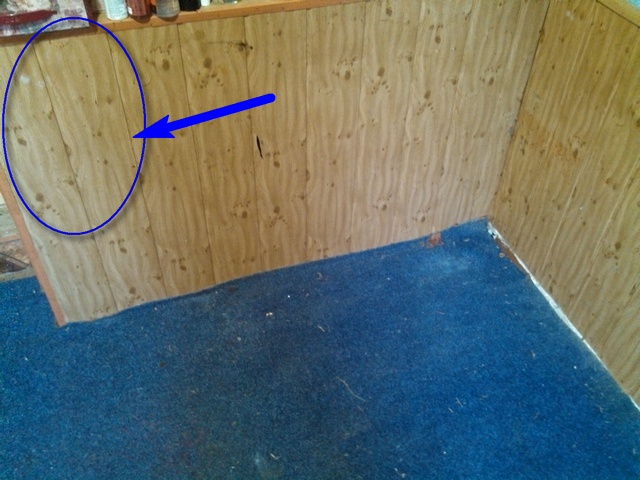
If we take “clean” dimensions for calculations, they are shown on the left fragment of the illustration. But in reality adobe walls, alas, are not distinguished by their evenness - on the right fragment, the red line shows the bends at floor level. You can, of course, make an attempt to level the walls to perfection - drywall will help. But this will certainly lead to the loss of an already small area of the room. The existing curvature of the walls had no effect on the feeling of comfortable living for us, and therefore, in due time, only the defects that stood out against the general background were corrected. Partially, the shortcomings were hidden by the finishing - clapboard cladding and the creation of a bedside shelf (it is shown in the diagram with a brown arrow, and it was decided to leave it, only with a slight “modernization”). But when laying the laminate at the starting stage, even the slight remaining curvature still had an effect - attention will be paid to this below.
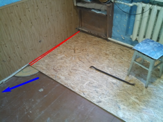
The second nuance is along external wall The return pipe of the heating circuit runs just above the level of the old floor - it is clearly visible in the photo above, and is shown with a blue arrow in the diagram. Previously, the heating system worked according to the principle natural circulation, so the pipe has a slope - on the left side of the room a sheet of plywood can be easily pushed under it, but on the right - the gap is too small for this. This also left a certain imprint on subsequent work.
The following laminate was chosen for the flooring - the Krono Original company, Castello classic series, Art Works model. Boards size 1285x192 mm, class 32, Dubble Click type locking connection.

Prices for laminate flooring of the Castello classic series
Castello classic
A simple calculation was carried out, and according to its results, 30 boards were purchased - three packages of 9 pieces each, plus three more boards. A reserve of approximately 10% was made, and it was taken into account that one board would be used to finish the remaining bedside shelf. The store administration immediately discussed the possibility of exchanging defects, purchasing additional boards, and even returning unused ones. True, it turned out that there was no need to resort to any of this measures.
Now – about the “warm floor” system. It was decided not to make the heated area continuous over the entire area. Those areas where a person’s foot usually “steps” are quite sufficient. As a result, we settled on the following scheme.

There is no particular point in placing infrared film under the bed (item 1). But when you get up on a cool morning, it will be very nice to put your bare feet on a heated section of the floor. Therefore, a meter-long piece of film (item 3) along the bed is planned here.
In the far right corner from the entrance there is work zone – desk(pos. 2) with a computer. From the door to the table and partially under it there runs a second “comfort zone” - a two-meter heating section (item 4).
In total, three linear meters of heating film elements are required. Most suitable option In terms of price and performance parameters, it turned out to be a South Korean-made film with a width of 500 mm and a specific power of 220 W/m². The total power of the created system is low - only 330 W, that is, no special additional load is expected on the home electrical network.

Included with the film heater were two coils of wire (stranded copper with a cross-section of 1.5 mm²) with blue and red insulation, a set of terminals and insulating pads. In addition, a thermostat was purchased separately for installation in a standard socket box. A model with push-button control and the possibility of weekly programming of operating modes was selected.
So, the basic materials were purchased. Others were also used - this will be mentioned in the course of further presentation.
It was planned to spend three days on the work. But, as it turned out in reality, it took five - due to inexperience, unforeseen problems, etc. But in the end everything was decided positively.
So, let's move on to considering the practical side - the actual progress of the work performed.
Floor with laminated coating and infrared film heating system - step by step and step by step
The first stage is preparing and leveling the floor
This stage at the planning stage seemed generally unproblematic. In practice, it turned out that not everything was so “rosy” and simple.
But under a laminated coating such a level difference is unacceptable - compliance with a single plane is required. Therefore, it was planned to carry out the alignment using OSB sheets 10 mm thick.
How this was done practically is in the table below (all pictures expand when you click the mouse).
| Illustration | |
|---|---|
 | The room is cleared of all the furniture in it. The carpet in some areas looks even worse than it previously seemed. |
 | The old wooden skirting boards were dismantled. They are already so unsightly that they went straight to the trash - for firewood. Instead, at the final stage of work, plastic ones will be installed, matching the floor covering. The blue ellipse shows the area of the bedside shelf where it is planned to convert it into a convenient niche for gadgets. And under this niche there will be a “warm floor” thermostat and a socket for a charger. Convenient - clapboard cladding eliminates the need to cut out sockets in the wall for socket boxes and a hole for the power cable. |
 | Finally, the old carpet is rolled up and taken out into the yard. Its back once had a rubberized base. This layer has already crumbled in large areas and remains on the floor as black dust (the arrows show the preserved areas of the base and with complete shedding of the substrate, right down to the pile). The picture is scary, and once again convinces me that the experience with carpet was probably my last. |
 | I had to immediately start cleaning - clear the floor of black rubber dust. This is after cleaning, during which I got dirty from head to toe. |
 | And this is the picture that emerged. By the way, my wife and I no longer remembered about this - that under the carpet we also leveled the surface with plywood. True, plywood is a very strong word. In fact, due to the shortage (at that time) of materials, all available scraps were used, and the result was this “patchwork quilt.” So the next and, it turns out, unplanned task is to dismantle this “mosaic”. |
 | This sounds easy, but in reality it took quite a lot of time and required a lot of effort. The difficulty is that only certain sections were secured to the boards with self-tapping screws. Mostly small nails with very frequent pitches predominate (shown by the red arrow). So there was a lot of fuss. Moreover, just to ensure safety, I didn’t want to leave extra nails under the electric “warm floor,” so after breaking out the plywood “patches,” they were not driven into the old plank floor, but pulled out. The opening floor is in very good condition, with the exception of one small area in the corner - it is outlined in the illustration with a yellow ellipse. |
 | In this section of the board there are also no signs of decomposition, but for some reason the covering here is assembled from short sections - perhaps a hatch into the cellar was once planned, and then the decision was changed. From below, the boards rested on chocks, which sank into the ground, which resulted in general instability and subsidence of this area. The repair turned out to be simple. Three crossbars were attached to the good-quality floor boards from below, under which the same lumps of support were placed. Well, then the short sections of boards that were removed were returned to their place. It turned out strong and stable. |
 | After cleaning the surfaces, we moved on to leveling the floor with OSB sheets. On this side and up to about three-quarters of the length of the room the floor is horizontal. And then the downward slope begins. Since the sheet is shorter than the length of the room, it is offset in an uneven direction. And here, on the remaining horizontal sections that do not require leveling, it will be easy to fix the missing narrow strips of OSB. |
 | The opposite side is another matter. Here the unevenness is even expressed in two ways. Firstly, the far left corner is not quite straight, and the edge of the sheet had to be trimmed somewhat (shown by the red lines). And secondly, and this is the main thing, the level is decreasing from almost zero in the far corner to approximately minus 45 mm in the near corner (the increase in the difference is shown by the blue arrow). There's some tinkering to be done here. |
 | It was decided to carry out the alignment using the following algorithm. To begin with, a beacon-platform is fitted and secured to the floor, which ensures the horizontal position of the sheet. This beacon is nothing more than a piece of timber of selected thickness (shown by the red arrow). Then the sheet was removed to the side, and picked up from this area using a regular level and a series of beacons were fixed along the wall to the far corner, where the difference goes to zero, that is, the areas become thinner (the direction is shown by the blue arrow). And then from each of these beacons, in a similar way, a line of platforms is made along the sheet, right up to the border of the transition to a flat section of the floor (a series of yellow arrows). After careful fitting, all platforms were screwed to the plank base with self-tapping screws (with preliminary drilling to prevent cracking). |
 | These are the areas before placing the sheet in place. By the way, on the far rows we didn’t even have to “build rows”, since the deformation of the plane there was small. And on the repaired section of the floor, it even became necessary to slightly remove the resulting protrusion with a plane. |
 | The sheet fit perfectly into place. Checking with a level proved its compliance with the horizontal plane. The beacon areas are located quite often, and when moving along the surface there was no deflection of the sheet (and believe me, I am quite tall and weighty). In addition, a little later another step was taken to make the coating more stable - this will be discussed below. Please note that the row of beacons closest to the edge is made so that it simultaneously serves as a support for the second sheet, which will then be laid end-to-end with the first. |
 | The sheet is fixed to the plank floor surface. Black self-tapping screws were used with a length of 35 mm (on a flat area of the floor) to 75 mm in areas of large differences. The illustration shows the “trajectory” of screwing in the fasteners, in increments of approximately 200 mm. From the edge of the sheet - at least 20 mm, otherwise you can get a crumbled area. The tightening torque on the screwdriver (ratchet) was adjusted so that the head of the screw was immersed in the thickness of the sheet by about half a millimeter. |
 | After screwing the sheet, it was decided to also fill the remaining cavities from below with polyurethane foam. In the right places between the beacon pads, holes with a diameter of 10 mm were drilled in the OSB so that the nose of the gun would fit into them well. Filling was carried out until foam appeared from the adjacent hole. It didn't require much foam - the gaps weren't that big. The illustration shows a picture after the foam has expanded and hardened. All protruding excess was cut off and removed. And the sheet, in addition to being supported on the platforms, also received a fairly hard cushion from below. His position became absolutely stable. In addition, the deformed section of the floor is located exactly where the bed is located. That is, no special dynamic loads are expected here. So you don’t have to worry about the reliability of the leveled surface. |
 | The algorithm for aligning the second sheet is exactly the same. From the lighthouse already standing in the center, a series of platforms should be fixed along the wall (red arrow) to the point of the greatest level difference (green arrow). And then rows of beacon-platforms are laid out towards the center of the room, before moving to the horizontal section (yellow arrows). There was no long rule at hand, so instead a two-meter piece of profile pipe was used - it turned out even more convenient: the pipe itself is heavy, and this simplified the selection of the height of the platforms. However, I had to tinker with cutting out the sheet itself - its near edge repeats the configuration of the bedside shelf and all the protruding corners at the entrance to the room. But this is in particular, just a little more marking and jigsaw work. By the way, when cutting and adjusting the sheets along the walls, a deformation gap of about 7-10 mm was left (due to the unevenness of the wall, it fluctuated somewhat within these limits). And between the sheets (and inserted fragments) a gap of about 5 mm was also left. These gaps are in case of linear expansion of the material when heated. |
 | The cavities under the second sheet were also filled with foam. After it hardens, the excess is cut off and removed. |
 | Next, it was the turn of the remaining areas that were not closed. Everything is simple here - fragments of the required size were cut out and, after adjustment, they were attached to the plank covering with self-tapping screws. Then all deformation gaps were also filled with polyurethane foam. Ignore the un-removed baseboard on this wall. It's just so firmly embedded in old wall, that it was decided not to touch it, otherwise a “new front” of work would appear. And according to preliminary estimates, after installing the laminated coating, it will be perfectly covered with a new baseboard. |
 | Finally, everything is finished, excess foam along the expansion joints is cut off, and cleaning is done with a vacuum cleaner. Before us is a ready-made, even, reliable coating for the subsequent installation of a “warm floor” system. |
The second stage – connecting the power line for the “warm floor”
In truth, this block of work was carried out in parallel with the first stage. There was enough time - until it froze polyurethane foam after each laid sheet of leveling coating. Yes, and I wanted to do all the “dirty” work right away - leaving them for later, and then cleaning again is hardly reasonable.
So, the power of the floor heating system is small - a maximum of 330 W. Plus, in parallel with the thermostat, it is planned to install an outlet to charge a smartphone and tablet, and, if necessary, to turn on the laptop power supply. That is, the power of this load is low. However, in the room where the renovation is being carried out, there was no line convenient for connection. But in the next room, through the left wall, there is a dedicated line with a copper wire with a cross-section of 1.5 mm² (that is, it is enough for 3 kW). And on this line there is only lighting (with LED lamp 13 W), night light and two sockets, also mainly used for chargers. That is, you can easily “cling” to it. And the location is such that it is possible to organize a supply line to the installation site of the “warm floor” thermostat with minimal disruption to the finish.
Although the load is low, just in case, for a “warm floor” with an outlet parallel to it, it was decided to install a separate 6-amp circuit breaker.
How this was all done is in the table below:
| Illustration | |
|---|---|
 | Three panels of the bedside shelf lining have been removed - they will be shortened and slightly altered. In the upper part there will be a convenient niche for all small things and a telephone, and in the lower part there will be a “warm floor” thermostat and an additional socket. This is where the power cable will be laid. Convenient - it can be easily hidden behind the remaining cladding. |
 | IN next room The socket from where power will go to the “warm floor” has been temporarily dismantled. To install the machine, a small built-in box with four module spaces was purchased. To recess it into the wall, a niche is cut out in it. The leveling wall cladding here is made of plasterboard, which made it possible to cut a very neat “window” exactly to the size of the box. Under the drywall - first the old plaster layer, and then it begins clay wall, in which it was easy to cut a niche of the required depth. |
 | True, under the layer of clay there was also brickwork, half a brick thick. But it is deep and does not interfere with the installation of the box. A hole is drilled through this masonry into the next room with a hammer drill to allow the cable to pass through. The niche for the box, in addition, is connected by a hidden channel to the adjacent socket - for parallel connection to the power line. Not shown in the photographs, but a piece of cable was immediately pulled through this channel and connected to the socket terminals. The phase will break through the machine, and the zero – through the standard zero bus of the box. |
 | Here is the same hole, but in the room where renovations are being carried out. When drilling, of course, a fair amount of plaster was turned out. But this is not scary - the wallpaper was prudently trimmed and tucked. All that remains is to cut a very small fine (it is conventionally shown here with a yellow arrow), about 200 mm long, to the edge of the cladding. And then the power cable will “dive” under the cladding, be placed under it and “float up” only at the location where the thermostat is installed. (The trajectory of its laying is shown by a green arrow). Looking ahead, I will say that after laying the cable, the torn area and the scratches were carefully sealed with gypsum putty, and after it had dried, the wallpaper was returned to its place. So there are no traces left. |
 | Here it is - the VVG 2x1.5 cable after laying it to the installation site of the thermostat. |
 | The removed lining panels are shortened at the top. In two of them, windows were cut out with a jigsaw for installing socket boxes. The socket boxes used are those that are used for drywall, that is, with stoppers that are pulled from behind. A small “arch” is cut out from the bottom of the central panel - this is for passing the power wires and the signal wire of the “warm floor” temperature sensor. The panels with socket boxes, of course, are just put in place for now, not secured. |
 | Looking ahead a little, we can immediately show that a regular socket was installed in the right socket, as planned. The cable from the next room is connected to its terminals. And another piece of the same cable extends from the terminals - it will be connected to the thermostat. For now he is left alone. It is important that when carrying out this switching, do not make a mistake with the location of the phase and zero - this is required for the correct operation of the programmable thermostat. Therefore, it is better to adhere to the recommended color coding of wires. In my case, blue (zero) and brown (phase). |
 | In the next room, the switching of wires also ends - the phase with a break through the machine, the zero through the bus without a break. The socket is returned to its place. The box is installed in a cut-out niche. |
 | The box was already installed well in the niche, but for greater reliability I decided to secure it with silicone hot-melt adhesive. And I didn’t have to mess with the solution, and it turned out very quickly, durable and nice. |
In fact, everything is done with the electrical connections - it is ready for further installation of the heating system. Naturally, I carried out a check - a short-term switching on with an audit of the correct location of the phase and zero. Everything turned out as it should.
The third stage – installation of film infrared “warm floor”
Let's move on to perhaps the most interesting stage. Everything is ready to begin work directly on the “warm floor” system.
| Illustration | Brief description of the operation performed |
|---|---|
 | The stage begins with a thorough cleaning. It is important that there are no small solid fragments left on the floor surface - it must be completely clean. And then the next step will be to lay an elastic insulating reflective substrate on the floor - foil polyethylene foam. It was purchased with a small reserve - 7 m². The roll has a width of 1000 mm, the thickness of the substrate is 5 mm. The necessary tools are a sharp knife, a stapler with staples, foil tape. Laying this layer solves two important problems at once: - firstly, the installation of an infrared floor itself requires a thermally insulating reflective layer to direct radiant energy upward; - secondly, the laminate laying technology involves the use of a thin elastic backing that conceals all possible minor irregularities grounds. |
 | Laying the substrate is a very simple operation. A strip is cut from a roll required length and placed on the floor with the foil side up. The edges rest against the walls, since, of course, no deformation gap is required here. I must say that even the stapler was not particularly needed - the material lays perfectly on the slightly rough OSB surface without moving. At first I fastened the sheets in the corners with staples, then I stopped - it’s quite possible without them. |
 | The next strip is laid end to end with the first. And then this joint line is glued on top with foil tape. The result is a continuous, seamless reflective coating. |
 | The last strip had to be cut to fit the remaining uncovered area, but this does not cause any difficulties. As a result, in literally 15 minutes the room is completely covered with a reflective substrate. |
 | It was decided to put the remaining large fragment of the substrate to good use. A reflective screen was made from it, which was attached to the heating radiator. I had to fiddle around a bit to get it in there, making the slots for the brackets. But now the heat transfer of the battery will be higher. |
 | We finished with the substrate - it was the turn of the film heaters. First of all, the purchased three-meter roll is cut into two sheets - 1 and 2 meters. The cut must be made exclusively along the drawn lines with the appropriate signature. On this film model, these lines are located in increments of 250 mm. The cut canvases are placed in the planned places. Important - they should lie with the shiny “copper” side down. By the way, if positioned correctly, all the inscriptions on the film become readable. Otherwise, they are obtained in a mirror image. |
 | After carefully checking the position of the film sheets so that they no longer move, they should be fixed to the floor. For this, reinforced construction tape was used - the canvases were glued to the substrate along both long edges. But so far – not completely. The edges must be left with a “degree of freedom” - they will have to be raised more than once when connecting wires and insulating cut busbars. It turned out as shown in the illustration. |
 | The heating film sheets are ready for switching. It's time to once again clarify the scheme according to which it will be produced. In order to avoid crossing wires on the floor, it was decided to supply phase and neutral from different sides of the canvases. The wire consumption is somewhat higher, but the amount that was given complete with the heating elements was quite enough. Where the phase will be located and where the zero will be located has absolutely no meaning for the heating film. The main thing is not to mistakenly place a phase and zero on one bus So, the illustration shows an electrical switching diagram. 1 - green The temperature sensor with its signal cable is shown. It will be located under a meter-long sheet of film, in the center, so that the sensor head fits exactly on the heating black carbon strip. 2 - points for connecting the terminals of phase wires to the bus bars of the heating fabrics. Accordingly, the red lines show the routes for laying these wires. 3 - neutral wires and points from the connection in the terminals with the busbars are shown in blue. 4 - it is mandatory to carefully insulate the places where the busbars of film heating elements are cut that are not used in switching. All the wires converge at one point - and it falls exactly on that same arched “window” cut out in one of the cladding panels. |
 | Work began with insulating the cut ends of the tires. The heaters were supplied with special insulating pads. They are a rectangular fragment of a rather thick elastic rubber-bitumen sheet, covered on one side with a polymer film, and on the other with a protective paper backing covering the adhesive layer. To isolate the area where the tire is cut, one such pad is required. |
 | To begin with, this paper backing is carefully removed. |
 | Then the pad with its adhesive layer is pressed from below to the cut point of the tire, so that approximately half of the pad ends up at the bottom - stuck to the surface of the film. |
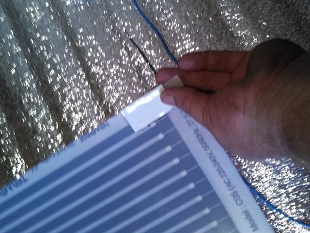 | After this, the insulating pad is folded over the edge of the sheet and glued on top of the film. Then, with a fairly significant application of finger effort, this resulting “cocoon” is compressed over its entire area. Essentially, the tire cut is insulated. |
 | This insulating cocoon ends up being quite thick, even after very tight crimping. But we can’t allow anything to stick out above the surface, otherwise there will be difficulties with laying the laminate. Therefore, exactly along the contour of the resulting “pattern”, a window is cut out in the substrate with a sharp knife. In this “nest” everything will be perfectly hidden flush with the general surface. |
 | Similar operations are carried out at all bus cutting points where there will be no switching, that is, in three more places. |
 | The next step is connecting the power supply wires to the heating elements. The wires are laid out on the floor approximately along the routes of their laying. These routes, by the way, can be drawn on the substrate in advance with a marker for convenience. |
 | The connection of wires to the busbars of film heaters is carried out using terminals, each of which has two large petals and a crimp clamp for the wire. The upper tab of the terminal must be inserted into a special “pocket” located in the area where the bus is cut. To make it easier to slip it in there, it is first recommended to widen this “pocket” somewhat with the tip of a thin screwdriver. |
 | Then the upper petal of the tire is inserted into this “pocket” and pushed in until it stops. |
 | The blades of the terminal are brought together - compressed, at first simply by the force of the fingers... |
 | ...and then, finally, they are crimped using pliers. Contact of the terminal with the bus is ensured - now you need to connect the wire to the terminal. |
 | This is also easy. The wire is stripped of insulation approximately 8 mm from the edge, the veins are twisted into a tight “pigtail”. Then this bare area is inserted into the terminal clamp, which is immediately then carefully crimped with pliers. The clamp also consists of two petals, and it is better to crimp them not immediately, but one by one. Well, if it is necessary to connect two wires in a terminal to connect heating films in parallel, then I used one side of the clamp for one conductor, the other for the other. It turned out securely and neatly. |
 | Immediately after such assembly, the finished terminal connection must be insulated. Two insulating pads will already be used. |
 | The first, after removing the protective paper backing, is glued from below. It should completely cover both the entrance to the bus and the entire terminal, capturing the beginning of the insulated section of the connected wire. |
 | After removing the paper backing, a second overlay is glued mirror-like to the bottom from above. |
 | The resulting knot is pressed very carefully with your fingers. By the way, the arrow in the illustration shows that, just in case, the places where the tire edges were insulated were also taped on top with strips of construction tape. This is not a requirement and is not specified anywhere, but the cost of adhesive tape is cheap, and the reliability is much higher. |
 | Windows are also cut out in the foil substrate for these isolated switching nodes. In addition, thin grooves are cut along the marked lines into which the wires are hidden. |
 | Similar operations are repeated with the second wire. It is important, we emphasize once again, not to connect two different wires to the same busbar on both sides of the heating element. |
 | After the power wires are connected to the heating film elements, you can install a temperature sensor. It will be placed in the center of the black carbon strip, in the middle of the second block of these strips from the edge, on a short meter section of the “warm floor” - its position from below is shown by the green arrow. |
 | Specifically, the sensor head is fixed in place on the back side of the film with a strip of construction tape. |
 | For the sensor itself, a window was also cut in the substrate. A groove is also made for the signal cable. However, it turned out that the sensor head is still too thick to be completely hidden in the elastic backing layer. That is, an unacceptable tubercle appears above it. |
 | I had to work with a chisel to cut out a recess in the OSB leveling sheet. After this, all sawdust was carefully removed, and the bottom of the resulting recess was taped with foil tape. After laying the sensor, the groove with the signal cable was sealed with tape on top. |
 | The switching of the heating elements is, in principle, completed. You can “beautify” - the film sheets are finally fixed to the floor surface along the perimeter with tape. Grooves are cut out for the wires, and after laying, they are immediately sealed with the same tape. |
 | All three wires (red phase, blue neutral and white signal temperature sensor) ultimately converge in one “finishing” groove, follow it to the wall and there “dive” into the cut arched passage. Nowhere on the floor surface did any wire intersect with another - this is very important to ensure the safe operation of the heating system. |
 | Finally, when the wires are brought behind the casing, that is, to the place where the thermostat is connected, the final “sealing” of all system elements located on the floor is carried out with tape. This is the picture we got. |
 | You can proceed to installing the temperature sensor and then checking the functionality of the system. |
 | In order not to have to deal with tinning the bare ends of the wires to clamp them into screw terminals thermostat, wherever it was required, I installed and crimped these terminal lugs. |
 | Here are both “cold ends” - this is what the wires coming from the heating elements are usually called. |
 | Just in case, I check the load resistance with a multimeter. The result was 137 ohms - very close to the value calculated by Ohm's law of 146 ohms. We can move on. |
 | Through the socket box, which remains empty for now, having cut windows in it, I insert wires in pairs - a power cable coming from a nearby outlet, “cold ends” from the floor heaters and a signal cable from the temperature sensor. All of them will be connected to the corresponding terminals of the thermostat. Naturally, all work is carried out with the power line de-energized - this can now be ensured by turning off the recently installed 6-amp machine. |
 | And now the panel with the socket box finally takes its place and is fixed with self-tapping screws to the frame (the fastener heads will subsequently be hidden by finishing corners). According to the rules, the thermostat must be located at least 400 mm from the floor level. In this case, it turned out to be 450 mm, that is, everything is within the normal range. |
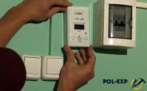
 | For the “warm floor” system, we purchased the following thermostat – it provides the ability to program operating modes by the hour per day, taking into account weekends and weekdays during the week. |
 | To install the thermostat, you must first disassemble it in order to get to the mounting support that will attach it to the socket box. |
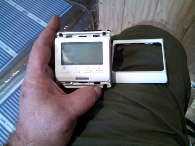 | The decorative frame is removed - it is simply held on by plastic latches. The metal bracket is clearly visible from above. |
 | This bracket is moved upward with the help of a screwdriver and thereby releases the attachment of the device to the caliper. |
 | That's it, disassembly is complete. |
 | The support is immediately attached to the socket box with two self-tapping screws. |
 | You can move on to connecting wires. On the back of the thermostat there are terminals with very clear indications of their purpose. 1 and 2 are the power cable, phase (L) and neutral (N), respectively. 3 and 4 – load, that is, the “cold ends” of the heating film elements are connected here. Both 6 and 7 are terminals for connecting a temperature sensor. Here the polarity of the wires does not matter. |
 | And since I have all the wires ready, switching takes only a few minutes. First, install and clamp the contacts of the temperature sensor into the terminals. |
 | Then - the wires from the load, observing the color marking of phase and zero (although, by and large, this does not really matter here either). |
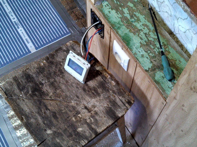 | And finally, the wires from the power line are connected, and here maintaining the correct position of the phase and zero is a prerequisite. The device is ready to test the functionality of the system. |
 | I turn on the power automatically. |
 | The message “OFF” appeared on the thermostat display - turned off. It’s already good – “signs of life” are visible. |
 | I press the power button. Floor heating does not start. But this is only because the factory presets on the thermostat are 24 degrees. And the work is carried out in early September in conditions of hellish heat. And the floor surface in the room itself already has a temperature of more than 28 degrees, as evidenced by the sensor readings located on the right side of the display. That is, the thermostat is working correctly - the power does not turn on. But you still need to check, so in manual mode I raise the heating limit to 33 degrees. It worked instantly - a heating symbol appeared on the screen, and after a few seconds my legs felt the temperature of the film increase. |
 | No more is needed. The system is functioning normally, so you can complete this stage of work. The power turns off again automatically, and the thermostat finally takes its regular place in the electrical outlet. There is no need to worry him anymore. |
The installation of the floor heating system is complete. And the next stage lies ahead - laying the laminated flooring.
Prices for film infrared heated floors
film infrared heated floor
Stage four – laying the laminated flooring
Laying laminate flooring, in principle, is not included in the list of traditional topics on the portal dedicated to heating and insulation. But abandoning the story like that, mid-sentence, is also not the case. Therefore, the subsequent stages will be considered until the end of the repair, but not to the slightest detail, but simply with an illustrated listing of the main operations. But still with the obligatory emphasis on some possible errors.
You might be interested in information about what it is
So, the stage began with another thorough cleaning - it is unacceptable to leave even small debris under the laminate, since the installation may not go well, and over time, squeaks in the coating may appear.
After cleaning, the entire floor surface was covered with polyethylene film 150 microns thick. In my case, I got by with one canvas, with an overlap of about 100 mm on the walls. If one sheet is not enough, then they are laid with an overlap of approximately 100 mm, with the obligatory gluing of the overlap line with waterproof construction tape.
What is it for? In essence, polyethylene becomes a waterproofing layer. Who knows if a bucket of water will be accidentally knocked over on the floor, or a full cup of tea will be dropped? Liquid penetration into the heating film elements must not be allowed.
The installation of the laminate itself did not seem so challenging task, since in the instruction video everything looked extremely simple:
Video: installation process of film heated floor under laminate
Was compiled approximate diagram installation At the same time, attention is drawn to one important point. In the conditions of the existing room, if you start by laying a whole board from the wall (widthwise), then at the end you end up with a narrow strip only about 10-12 mm thick. Naturally, it is impossible to snap such a narrow fragment into the lock efficiently, and you won’t leave such a gap either. This means that it is necessary to reduce the width of the starting strip by about 60 mm - then the finishing strip will become quite acceptable for laying the width.
As can be seen from the video instructions, for lock connection The next panel is joined to the previously laid one at an angle, and then, when lowered down, the lock snaps into place.
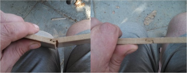
But I have a heating system return pipe running along one wall, which was noted earlier. Therefore, the coating has to be shortened somewhat (the space behind the pipe was subsequently filled with small scraps - they are almost invisible there). But this, in turn, means that it is impossible to carry out high-quality wedging of the starting strip from the outside wall.
To wedge the coating from the remaining walls, liners were prepared - sawn from the remaining waste OSB sheet 10 mm.

Everything seems to be ready - we can start.
The first strip was prepared and laid. And immediately the first problem is that due to the existing curvature of the wall, this strip cannot be stably positioned along it with emphasis on the wedge inserts. I had to make a non-trivial decision - temporarily, in the area that would be covered by the baseboard, fix the assembled strip to the floor surface with screws. They will be removed at the end of installation work.
But this problem turned out to be not the main one. After assembling the second strip, a dozen unsuccessful attempts were made to connect it with a lock to the first. Nothing worked - on one side the connection goes approximately to the center of the room - on the other the lock does not work. And vice versa. Frankly speaking, there was a slight panic until I thought of looking for advice on forums on the Internet. It turns out that the case is quite common and can be due to several reasons:
1 - the floor surface may have, although not particularly noticeable, curvilinear deformation that interferes with the normal operation of the locks.
I was sure that my gender was straight, but I still checked again to make sure that this was not the reason.
2 – after purchase, the laminate was not allowed to sit in the temperature and humidity conditions of the installation room.
Also by the way - the boards were unpacked and lay in the next room with exactly the same conditions all the time that the floor was leveled and its heating system was installed. That is, three days is the minimum.
3 – factory defect of laminate. In any game, no, no, and there are boards with imperceptible distortions of shape. Moreover, it happens that the amount of such cancer reaches as much as 10%!
I decided to check it out. And when inspecting the first board of the second row, it was discovered that its end side with the lock was not completely perpendicular to the longitudinal one! That is, when assembling a strip, the result is not a straight line, but a broken line invisible to the eye, and the error at the opposite end of the assembled strip is a good one and a half millimeters! Naturally, there can be no talk of any operation of the locks along the entire length.
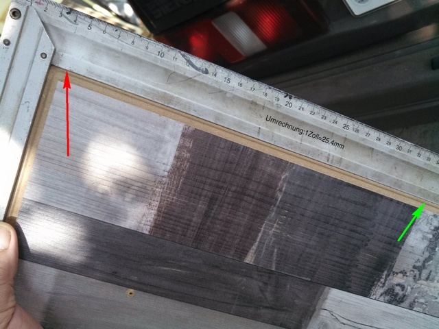
I put this board aside and took another one with preliminary control of the corners. And the strip went down with ease, the locks immediately worked along the entire length!
I carefully checked all subsequent boards for the straightness of the corners. But, as it turned out, this one was the only one that was defective - it then went to finishing work.
Well, in the future - no special problems emerged, and installation went very smoothly. There were a couple of “rough spots” - I’ll mention them below:
| Illustration | Brief description of the operations performed |
|---|---|
 | Unfortunately, in the excitement of the “struggle” with the starting lines and the experiences associated with it, I forgot about photography. So in the first illustration there are already two rows laid. But the most important thing is still visible. Firstly, these are inserts that had to be laid only along one wall - the reason has already been explained. Secondly, the screws with which the starting strip was fixed to the floor surface are visible. They were subsequently removed. |
| And in this picture you can clearly see the opposite edge - the same return pipe of the heating system that interferes with the “classic” installation of the laminated coating. So I had to adapt. |
 | The third strip has already been assembled along the length (with end locks) and laid out along the longitudinal line of the lock. All that remains is to lift it, move it forward a little and lower it - it easily connected with the second one. |
 | But with the fourth stripe there is a hitch again, he resists. True, the reason was discovered quickly. At the corner, at the intersection of two milled grooves of the lock, there remains such a thin spike. It has no practical meaning - just a “production cost”. But, as it turned out, this “bastard” is capable of jamming and interfering with the connection. |
 | The solution is trivial - before assembling the next strip, all such spikes were cut off with a knife. |
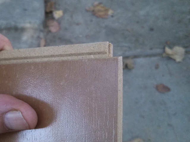 | This is the picture we got. |
 | And in order not to stop at all, it makes sense to completely check the locks of each board. It doesn't take much time. |
 | For example, in the locking groove of one of the boards there was also a small “surprise” in the form of a caked, glued spool. Surely, if it had remained unnoticed, there would have been a problem during assembly. |
 | To check the grooves, I used the back side of a jigsaw file. I ran it along the entire length and the groove was guaranteed to be clean. If there is any obstacle, you will definitely feel it. |
 | Otherwise, installation went quickly, almost as easily as shown in the video instructions. And the main problem was, rather, the thoughtful placement of the boards according to the pattern. So that identical patterns on this, say, not quite ordinary surface design, do not appear in a row. And on top of that, it is important to rationally use the remaining trimmings to minimize waste. But a pre-compiled diagram, which takes into account the necessary shift of the boards and the possibility of using the remaining fragments, helps to cope with this particular problem without much difficulty. |
 | It’s important to always have a broom and dustpan at hand. Small debris may get on your feet, the inadmissibility of which has already been mentioned. By the way, a small solid fragment remaining under the laminate can be very potentially dangerous. Over time, under the influence of dynamic load on the coating, it is quite capable of gradually “chewing through” both the plastic film and the heating element. So we monitor cleanliness from the beginning to the very end of installation. |
 | And in just a few hours - the finished floor covering. The last row is narrow, only about 80 mm wide, but it is also well secured with a lock with the previous one. And so that it doesn’t get “bulky”, an ottoman was temporarily placed. With its (small) weight it will help this narrow strip to “lie down” in place. After completing the installation of the last row, the screws were removed from the first strip and all spacer inserts were removed. The floor is left in this form until the next day - it is advisable to give it a little time to adapt to the assembled state. |
The next morning - everything is fine, the boards lie amazingly evenly, there are no creaks or bends anywhere. We tried to turn on the “warm floor” system (again with a slightly elevated heating threshold). Literally in a minute there is a quite noticeable effect. Naturally, after this the system was immediately turned off - its time would come later, with the onset of cold weather.
The fifth stage, the final one – “finishing final beauty”
Here I will try to be as short as possible – just to demonstrate the result of the repair as a whole.
| Illustration | Brief description of the operation performed |
|---|---|
 | The task of the day is to put everything in order, finish the decoration, bring in the furniture and hand over finished room at the disposal of the hostess. I start with a niche shelf above the thermostat |
 | From the laminate fragments remaining after cutting, I cut out parts for the bottom and side walls of this niche. I immediately install them in place - the bottom is on small self-tapping screws, the heads of which will then be hidden decorative corner, walls - with silicone hot melt adhesive. The fixation turned out to be very good. |
 | The next step is a long bedside shelf. This is where the defective board will go. It is cut to size, laid, and secured with small self-tapping screws. |
 | Next comes the framing of all external and internal corners with a decorative plastic corner. |
 | Niche shelf after framing. |
 | After this, a long bedside shelf is framed. |
 | It's time to install the skirting boards. The first step is to cut off the plastic film protruding around the perimeter from under the coating. The blanking strips covering the cable channel are removed from the baseboards. There are no cables to be laid - just fastening screws will be screwed through this channel. |
 | Marking is being done - first, the most complex unit at the door will be designed, with several external and internal corners. |
 | An assembly is assembled from short sections of plinth and profile parts (external and internal corners and caps). |
 | And so that it does not fall apart when final installation, the parts are fixed to each other from the back with small drops of silicone hot-melt adhesive. |
 | Fastening the corner unit through the cable channel with a self-tapping screw. |
 | On a straight section everything is much faster. |
 | After fixing the plinth, the cap strip of the required length is cut out and installed in place. |
 | Another inner corner - and the left wall. |
 | There is no need for a plinth along the outer wall (there is a return pipe there), that is, there remains one more small area to the right of the door. |
 | The previously removed fragment of wallpaper was carefully glued in place where the cable passed through the wall. |
 | You can bring in furniture. But in order not to scratch the laminate, these elastic pads are glued to the legs of the bed, chairs, and tables. They are presented in a wide range in the store and are inexpensive. |
 | The bed is in place. |
 | And then - a temporary workplace. Temporary because it was decided not to bring the old desk back. - it will be too disharmonious with the updated look of the room. It will be used as consumable material in the manufacture of a new homemade comfortable table. |
 | By the way, here it is, a table made a little later - style and design in strict accordance with the wishes of the owner of the room. |
Well, that’s all - the “full stop” was reached around lunchtime on the fifth day.
* * * * * * *
The renovation has been going on for two years now. That is, it is possible to evaluate the intermediate results of operation.
The coating is reliable - no creaks or areas of instability appeared.
The underfloor heating works perfectly. In accordance with the instructions supplied with the thermostat, the system operating modes were programmed. It turns on to heat up to a level of 25 °C at 5.45 and works in this mode until 8.00 - while my daughter is getting ready for school (first to the gymnasium, and now to the university). From 8.00 to 15.00 the heating threshold is 18 °C, so the heating elements practically do not work at this time. I repeat that the house has good heating and it is never cold, that is, there is no need to run a “warm floor” at a time when no one is walking on it. From 15.00 to 23.00 - again at 25 ° C, at night - 18 ° C. On weekends, the mode is divided only into daytime (heating) and nighttime.
You may be interested in information on how to install
I can’t say that this mode of operation had any significant effect on the overall energy consumption. Everything turned out really very economical.
But in winter it’s really nice to walk into a room barefoot – a feeling of increased comfort. And in particular, of course, the cat and cat appreciated this - in the cold they like to sleep on the floor in their daughter’s room.
Let's finish here. Don’t judge too harshly - it was my first experience with both flooring and laminate, and it seemed to me that it was quite successful. I will be glad to listen to comments, suggestions, and critical statements. I will answer your questions. read on the website.
You might be interested in information on how to install .

Evgeniy AfanasyevChief Editor
Author of the publication 24.08.2018
![]()