Building an energy-efficient house is the dream of every developer. Many believe that to achieve this goal it is enough to insulate the perimeter of the building and provide it with modern windows. But is this issue so easily resolved? It turns out not. Only by insulating the building envelope and installing sealed window units it is impossible to ensure comfortable living and full energy saving of the building. For some reason, many people forget to take into account the need to use ventilation - supply and exhaust units (PVU).
To save internal heat premises it is necessary to equip the supply and exhaust ventilation with a heat exchanger — air recuperator, which will utilize the heat of the air flow emanating from the room, giving it to the supply air. Such systems are widely used in Western Europe, ensuring the construction of buildings with a level of heat loss that is 5-10 times lower compared to conventional housing stock. By recycling exhaust air heat, they save up to 70% of heating costs and thus pay off in the shortest possible time, usually 3-5 years.
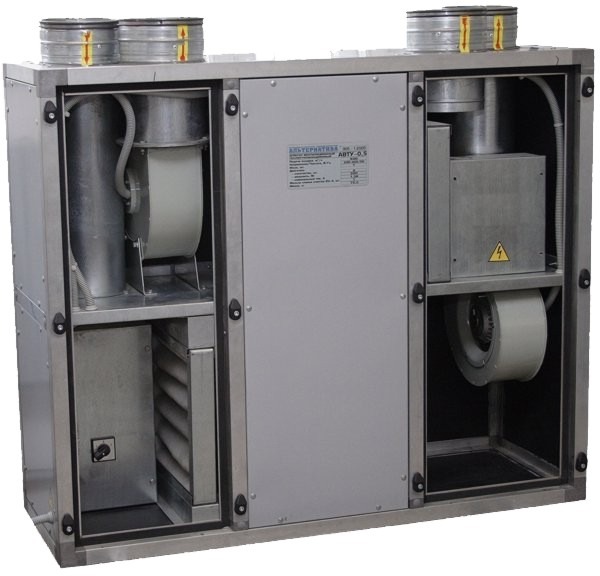
Small-sized supply and exhaust systems with heat recovery type AVTU, which are designed specifically for use in residential and other small premises. They supply the building with fresh, heated air, purified from street dust.
Ventilation exhaust energy in modern buildings reaches 50% of the total level of heat loss, therefore a building is called energy efficient if, in addition to insulating the building envelope and installing sealed window groups, the energy returned to the room by recycling the heat of ventilation emissions is used.
Duration heating season in energy efficient buildings can be reduced by more than a month.
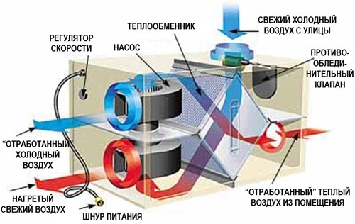
Operating principle of the PVU
It is as follows. Heated air is taken in through air intakes in the most humid rooms (kitchen, bathroom, toilet, utility room, etc.) and removed to the outside of the building through air ducts. However, before leaving the building, it passes through the heat exchanger of the recuperator, where it leaves some of the heat. This heat heats up what is taken from outside. cold air(it also passes through the same heat exchanger, but in a different direction) and is supplied inside (living room, bedrooms, offices, etc.). Thus, there is constant air circulation inside the room.

Operating principle of an air handling unit with heat recovery
A supply and exhaust unit with a recuperator can be of various capacities and sizes - this depends on the volume of the ventilated premises and their functional purpose. The most easy installation is a thermally and acoustically isolated set of interconnected elements enclosed in a steel case: a heat exchanger, two fans, filters, sometimes a heating element, a condensate removal system (the automation unit, electrical circuit elements and air ducts are not considered in this context).
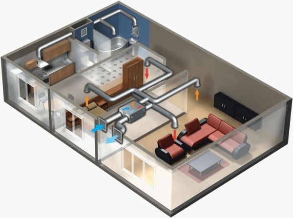
Organization of air exchange in the premises of a residential cottage
During operation of the installation, two air flows pass through the heat exchanger - internal and external, which do not mix. Depending on the design of the heat exchanger, recuperators come in several types.
The most far-sighted homeowners design two ventilation systems in their buildings at once: gravity (natural) and mechanical with heat recovery (forced). The natural ventilation system in this case is emergency and serves in case of malfunctions in the operation of the air handling unit and is used mainly during the unheated period. It should be remembered that during operation of the mechanical ventilation system, the gravity air ducts must be tightly closed. Otherwise, the effectiveness of forced ventilation will be lost.
Plate recuperators
Exhaust and supply air pass through both sides of the row of plates. In this case, in plate recuperators a certain amount of condensate may form on the plates. Therefore, they must be equipped with condensate drains. Condensate collectors must have a water seal that prevents the fan from capturing and delivering water into the channel.
Operating principle of an air handling unit with heat recovery
Due to condensation, there is a serious risk of ice formation, which is why a defrosting system is necessary. Heat recovery can be regulated by a bypass valve that controls the flow of air passing through the recuperator. The plate recuperator has no moving parts. It is characterized by high efficiency (50-90%).

Plate recuperator
Installations of this type from the manufacturer T.M. have proven themselves well. Naveka - Node1. They have an aluminum recuperator, drainage system for draining condensate and an anti-freezing system for the recuperator. And also the quietest fans in their class, an electric or water heater, built-in automation and a remote control with setting modes and operating schedules.

Rotary recuperators
Heat is transferred by a rotor rotating between the exhaust and supply channels. This open system, and therefore there is a high risk that dirt and odors can move from the exhaust air to the supply air, which can be avoided to some extent if the fans are positioned correctly. The level of heat recovery can be adjusted by the rotor speed. In a rotary heat exchanger, the risk of freezing is low. Rotary recuperators have moving parts. They are also characterized by high efficiency (75-85%).

Rotary recuperator
This solution was successfully implemented by the manufacturer t.m. Naveka in Node3 series installations. The units have an anti-freeze protection system, built-in automation and a remote control. In the Vertical version, the units have thermal and noise insulation made of non-combustible mineral wool 50 mm thick, and the possibility of outdoor (street) installation and operation.

Recuperators with intermediate coolant
In this design, the coolant (water or a water-glycol solution) circulates between two heat exchangers, one of which is located in the exhaust duct, and the other in the supply duct. The coolant is heated by the exhaust air and then transfers heat to the supply air. The coolant circulates in a closed system, and there is no risk of transfer of contaminants from the exhaust air to the supply air. Heat transfer can be regulated by changing the circulation rate of the coolant. These recuperators do not contain moving parts and have low efficiency (45-60%).

Recuperator with intermediate coolant
Chamber recuperators
In such a recuperator, the chamber is divided into two parts by a damper. The exhaust air heats one part of the chamber, then the damper changes the direction of the air flow so that the supply air is heated by the heated walls of the chamber. In this case, pollution and odors can be transferred from the exhaust air to the supply air. The only moving part of the recuperator is the damper. The unit is characterized by high efficiency (80-90%).

Chamber recuperator
Heat pipes
This recuperator consists of closed system tubes filled with freon, which evaporates when heated by the removed air. When the supply air passes along the tubes, the vapor condenses and turns back into liquid. The transfer of contaminants in this design is excluded. The recuperator has no moving parts, but has a relatively low efficiency (50-70%).

Channel-type recuperator based on heat pipes
The most widely used in practice are plate and rotary recuperators. Moreover, there are models of recuperators in which two can be installed in series plate heat exchanger. They are highly efficient.

Two-stage recuperation with two rotors
The amount of heat taken through the heat exchanger depends on a number of factors, in particular, the temperature of the indoor and outdoor air, its humidity, and air flow speed. The greater the temperature difference between inside and outside the room, the greater the humidity, the greater the effect of the recuperator. By the way, most installations have the possibility of installation for the summer period instead of a conventional heat exchanger, a so-called summer cassette, which allows for air flow without a recovery process. In addition, in some cases it is possible to change the direction of air flows inside the installation, so that they bypass the heat exchanger.

Main characteristics and features of heat exchanger types
Fans
Air movement is provided by fans - supply and exhaust, although you can find systems with an integrated supply and exhaust fan that is powered by a single motor. In simple models, fans have three speed levels: normal, reduced (used for operation at night or in the absence of residents, if this is a house or apartment) and maximum (used when the highest level of air exchange is needed). Some modern models fans have many more speed levels, which makes it possible to better meet the needs of system users at different levels of ventilation intensity.
The fans can be controlled automatically. Control panels are usually installed indoors in places convenient for their use. Temporary programmers allow you to set fan speeds throughout the day or week. In addition, some advanced models can be integrated into a smart home system and controlled by a central computer. The operation of the recuperator can also depend on the level of humidity in the premises (this requires the installation of appropriate sensors) and even the level of carbon dioxide.
Since the ventilation system must operate around the clock, high quality fans are an extremely important feature of the air handling unit.
Filters
Air taken from outside must be supplied to the room only after passing through a filter. Typically, recuperators are equipped with filters that retain particles up to 0.5 microns in size. This filter corresponds to class EU7 according to DIN or F7, according to European standards. Thus, the filter traps dust, fungal spores, pollen, and soot.
This feature of the air handling unit should be appreciated by allergy sufferers. At the same time, a filter is also installed in the exhaust system in front of the heat exchanger. True, its class is slightly lower - EU3 (G3). It protects the heat exchanger from contaminants that are removed from the premises along with the air. Filters are made from synthetic materials, they can be either single- or reusable. The material of the latter should be easy to clean. These filters can be shaken out and washed. Some models of recovery units have filter contamination sensors, which at a certain moment signal the need to replace or clean the filter.
Heating elements
Of course, a situation where the supply air is heated by the heat removed would be ideal. But in some cases this cannot be achieved. For example, if it is -25°C outside the window, then the temperature of the exhaust air, no matter what the efficiency of the heat exchanger, will not be enough to warm the supply air to a comfortable temperature. In this regard, recuperators are equipped electrical system additional heating of the air supplied to the premises. As practice shows, heating supply air is already needed if the outside temperature is less than -10’C.
The heating element is also controlled automatically and turns on depending on the program if the selected heat is not enough to heat the supply air in accordance with the set parameters. It is usually mounted together with a heat exchanger. The power and dimensions of the heating elements depend on the power of the entire installation.
It happens that with high air humidity and severe frost, condensation forms on the heat exchanger, which can freeze. To avoid this phenomenon, there are several technical solutions.
For example, the supply fan can work intermittently (turn on every half hour for five minutes), and then the exhaust fan works, and warm air, passing through the heat exchanger, protects it from the formation of ice.
The second, fairly common solution, is to direct part of the cold air flow past the heat exchanger. There are a number of other methods, including the use of an electric heater, which partially heats the air coming from outside in front of the heat exchanger. The resulting condensate should not be collected inside the unit, but removed through the pipeline system either directly into the sewer system or to another place provided by the design.
During construction individual houses it is possible to use a design diagram for a forced ventilation system with air intake at a certain distance from the house and delivering it to the air handling unit through air ducts located in the ground, below the soil freezing level. During the passage through such a channel, the air temperature will increase, which reduces the risk of condensation and ice formation on the heat exchanger and generally increases the efficiency of the recuperator.
Air ducts
As we have already noted, installation of supply and exhaust ventilation is much easier to perform in a building under construction than in one already in use. Therefore, its design should be an element of everything construction project. Typically, the installation is located in unused attics (this makes it easier to ensure cleaner air intake), in basements, boiler rooms, utility rooms and utility rooms. It is important that it is a dry room with positive temperatures. Air ducts in unheated room must be thermally insulated. Indoors they are usually installed behind suspended ceilings.
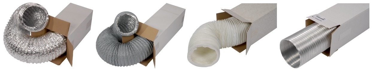
Aluminum or plastic flexible air ducts
In practice, various types of air ducts are used. The most convenient to install - aluminum or plastic flexible air ducts in the form of a pipe, reinforced with steel wire. Pipes can also be insulated with mineral wool. Air ducts of rectangular or square cross-section are also used. Ventilation grilles are usually mounted in walls or ceilings. Experts recommend as the most convenient option use anemostats with adjustable flow for air flow, although most often conventional grilles are used for these purposes. Supply air should be taken in places where it is least susceptible to contamination.
In conclusion, several videos on the use of air handling units with heat recovery:
Design and principle of operation of a plate air recuperator.
Using an air recuperator as the main means to combat the formation of mold and mildew in a residential area.
Supply and exhaust ventilation units with heat recovery appeared relatively recently, but quickly gained popularity and became a fairly popular system. The devices are capable of fully ventilating the room during the cold period, while maintaining the optimal temperature regime of the incoming air.

What it is?
When using supply and exhaust ventilation in the autumn-winter period, the question of preserving heat in the room often arises. The flow of cold air coming from the ventilation rushes to the floor and contributes to the creation of an unfavorable microclimate. The most common way to solve this problem is to install a heater that heats the flow of cold street air before supplying it to the room. However, this method is quite energy-consuming and does not prevent heat loss in the room.

The best solution to the problem is to equip the ventilation system with a recuperator. The recuperator is a device in which the air outflow and supply channels are located in close proximity to each other. The recuperation unit allows partial transfer of heat from the air leaving the room to the incoming air. Thanks to heat exchange technology between multi-directional air currents It is possible to save up to 90% of electricity; in addition, in the summer, the device can be used to cool incoming air masses.


Specifications
The heat recuperator consists of a housing, which is covered with heat and sound insulating materials and is made of sheet steel. The device body is quite durable and can withstand weight and vibration loads. The housing has inflow and outflow openings, and air movement through the device is ensured by two fans, usually of an axial or centrifugal type. The need to install them is due to a significant slowdown in natural air circulation, which is caused by the high aerodynamic resistance of the recuperator. To prevent the suction of fallen leaves, small birds or mechanical debris, an air intake grille is installed on the inlet located on the street side. The same opening, but on the room side, is also equipped with a grille or diffuser that evenly distributes air flows. When installing branched systems, air ducts are mounted to the openings.

In addition, the inlets of both flows are equipped with fine filters that protect the system from dust and grease droplets. This protects the heat exchanger channels from clogging and significantly extends the service life of the equipment. However, the installation of filters is complicated by the need to constantly monitor their condition, clean them, and, if necessary, replace them. Otherwise, a clogged filter will act as a natural barrier to air flow, causing resistance to increase and the fan to break.

According to the type of design, recuperator filters can be dry, wet or electrostatic. The choice of the right model depends on the power of the device, physical properties and chemical composition exhaust air, as well as the personal preferences of the buyer.
In addition to fans and filters, recuperators include heating elements, which can be water or electric. Each heater is equipped with a temperature relay and is capable of automatically turning on if the heat leaving the house cannot cope with heating the incoming air. The power of the heaters is selected in strict accordance with the volume of the room and the operating performance of the ventilation system. However, in some devices, heating elements only protect the heat exchanger from freezing and do not affect the temperature of the incoming air.


Water heater elements are more economical. This is explained by the fact that the coolant that moves along the copper coil enters it from the heating system of the house. The coil heats the plates, which, in turn, give off heat to the air flow. The water heater regulation system is represented by a three-way valve that opens and closes the water supply, a throttle valve that reduces or increases its speed, and a mixing unit that regulates the temperature. Water heaters are installed in an air duct system with a rectangular or square cross-section.


Electric heaters are often installed on air ducts with round, and their heating element is a spiral. For correct and efficient operation of the spiral heater, the air flow speed must be greater than or equal to 2 m/s, the air temperature must be 0-30 degrees, and the humidity of the passing masses must not exceed 80%. All electric heaters are equipped with an operation timer and a thermal relay that turns off the device if it overheats.


In addition to the standard set of elements, at the request of the consumer, air ionizers and humidifiers are installed in recuperators, and the most modern models are equipped with an electronic control unit and a function for programming the operating mode, depending on external and internal conditions. The instrument panels are aesthetically pleasing appearance, allowing recuperators to fit organically into the ventilation system and not disturb the harmony of the room.

Principle of operation
In order to better understand how the recuperative system works, you should refer to the translation of the word “recuperator”. Literally it means “return of used”, in this context – heat exchange. In ventilation systems, the recuperator takes heat from the air leaving the room and transfers it to incoming air flows. The temperature difference between multidirectional air jets can reach 50 degrees. In the summer, the device works in reverse and cools the air coming from the street to the temperature of the outlet. On average, the efficiency of devices is 65%, which allows rational use of energy resources and significant savings on electricity.


In practice, heat exchange in a recuperator looks like this: Forced ventilation drives an excess volume of air into the room, as a result of which contaminated masses are forced to leave the room through the exhaust duct. The escaping warm air passes through the heat exchanger, heating the walls of the structure. At the same time, a flow of cold air moves towards it, which takes away the heat received by the heat exchanger without mixing with the exhaust flows.

However, cooling the air leaving the room leads to the formation of condensation. If the fans work well, imparting high speed to the air masses, the condensate does not have time to fall onto the walls of the device and goes out into the street along with the air stream. But if the air speed was not high enough, then water begins to accumulate inside the device. For these purposes, the design of the recuperator includes a tray, which is located at a slight inclination towards the drain hole.


Through the drain hole, water enters a closed tank, which is installed on the side of the room. This is dictated by the fact that accumulated water can freeze the outflow channels and the condensate will have nowhere to drain. Use collected water not recommended for humidifiers: the liquid may contain a large number of pathogenic microorganisms, and therefore must be poured into the sewer system.

However, if ice does form from condensation, it is recommended to install additional equipment - a bypass. This device is made in the form of a bypass channel through which supply air will enter the room. As a result, the heat exchanger does not heat the incoming flows, but spends its heat exclusively on melting the ice. The incoming air, in turn, is heated by a heater, which turns on synchronously with the bypass. After all the ice has been melted and the water has been discharged into the storage tank, the bypass is turned off and the recuperator begins to operate normally.


In addition to installing a bypass, hygroscopic cellulose is used to combat icing. The material is located in special cassettes and absorbs moisture before it has time to fall into condensation. Moisture vapor passes through the cellulose layer and returns to the room with the incoming flow. The advantages of such devices are simple installation, the optional installation of a condensate collector and storage tank. In addition, the operating efficiency of cellulose recuperator cassettes does not depend on external conditions, and the efficiency is more than 80%. The disadvantages include the inability to use in rooms with excess humidity and the high cost of some models.

Types of recuperators
Modern market ventilation equipment presents a wide selection of recuperators of different types, differing from each other both in design and in the method of heat exchange between flows.
- Plate models are the simplest and most common type of recuperator, characterized by low cost and long service life. The heat exchanger of the models consists of thin aluminum plates, which have high thermal conductivity and significantly increase the efficiency of the devices, which in plate models can reach 90%. High efficiency indicators are due to the peculiarity of the structure of the heat exchanger, the plates in which are located in such a way that both flows, alternating, pass between them at an angle of 90 degrees to each other. The sequence of passing warm and cold jets was made possible by bending the edges on the plates and sealing the joints using polyester resins. In addition to aluminum, alloys of copper and brass, as well as polymer hydrophobic plastics, are used to produce plates. However, in addition to their advantages, plate recuperators also have their weaknesses. The downside of the models is the high risk of condensation and ice formation, which is due to the plates being too close to each other.


- Rotary models consist of a housing inside which a cylindrical rotor consisting of profiled plates rotates. During rotation of the rotor, heat is transferred from the outgoing flows to the incoming ones, as a result of which a slight mixing of the masses is observed. And although the mixing rate is not critical and usually does not exceed 7%, such models are not used in children's and medical institutions. The level of air mass recovery depends entirely on the rotor rotation speed, which is set manually. The efficiency of rotary models is 75-90%, the risk of ice formation is minimal. The latter is due to the fact that most of the moisture is retained in the drum and then evaporates. The disadvantages include difficulty in maintenance, high noise load, which is due to the presence of moving mechanisms, as well as the size of the device, the impossibility of installing on a wall and the likelihood of the spread of odors and dust during operation.


- Chamber models consist of two chambers, between which there is a common damper. After warming up, it begins to turn and let cold air into warm chamber. Then the heated air goes into the room, the damper closes and the process repeats again. However, the chamber recuperator has not gained wide popularity. This is due to the fact that the damper is not able to ensure complete sealing of the chambers, so the air flows are mixed.


- Tubular models consist of large quantity tubes containing freon. During the heating process from the outgoing flows, the gas rises to the upper sections of the tubes and heats the incoming flows. After heat transfer occurs, freon takes on a liquid form and flows into the lower sections of the tubes. The advantages of tubular recuperators include a fairly high efficiency, reaching 70%, the absence of moving elements, the absence of hum during operation, small size and long term services. Disadvantages are considered heavy weight models, which is due to the presence of metal pipes in the design.


- Models with intermediate coolant consist of two separate air ducts passing through a heat exchanger filled with a water-glycol solution. As a result of passing through the heating unit, the exhaust air transfers heat to the coolant, which, in turn, heats the incoming flow. The advantages of the model include its wear resistance, due to the absence of moving parts, and among the disadvantages are low efficiency, reaching only 60%, and a predisposition to condensation formation.

How to choose?
Thanks to the wide variety of recuperators presented to consumers, choosing the right model will not be difficult. Moreover, each type of device has its own narrow specialization and recommended installation location. So, when purchasing a device for an apartment or private house, it is better to choose a classic plate model with aluminum plates. Such devices do not require maintenance, do not require regular maintenance and have a long service life.

This model is perfect for use in an apartment building. This is due to the low noise level during its operation and compact dimensions. Tubular standard models have also proven themselves well for private use: they are small in size and do not buzz. However, the cost of such recuperators is slightly higher than the cost of plate products, so the choice of device depends on financial opportunities and personal preferences of the owners.

When choosing a model for a production workshop, non-food warehouse or underground parking lot, you should choose rotary devices. Such devices have great power and high performance, which is one of the main criteria for working over large areas. Recuperators with intermediate coolant have also proven themselves well, but due to their low efficiency they are not as in demand as drum units.

An important factor when choosing a device is its price. Yes, the most budget options plate heat exchangers can be purchased for 27,000 rubles, while a powerful rotary heat recovery unit with additional fans and a built-in filtration system will cost about 250,000 rubles.
Design and calculation examples
In order not to make a mistake when choosing a recuperator, you should calculate the efficiency and operating efficiency of the device. To calculate the efficiency, use the following formula: K = (Tp – Tn) / (Tv – Tn), where Tp denotes the temperature of the incoming flow, Tn – outside temperature, and TV – room temperature. Next, you need to compare your value with the maximum possible efficiency indicator of the purchased device. Typically this value is specified in technical passport model or other accompanying documentation. However, when comparing the desired efficiency and that indicated in the passport, you should remember that in fact this coefficient will be slightly lower than stated in the document.

Knowing the efficiency of a particular model, you can calculate its effectiveness. This can be done using the following formula: E (W) = 0.36xPxKx (Tv - Tn), where P will denote air flow and is measured in m3/h. After all the calculations have been made, you should compare the costs of purchasing a recuperator with its efficiency, converted into monetary equivalent. If the purchase justifies itself, you can safely purchase the device. Otherwise, it is worth considering alternative methods of heating the incoming air or installing a number of simpler devices.

When independently designing a device, it should be taken into account that counterflow devices have the maximum heat transfer efficiency. They are followed by cross-flow ducts, and in last place are unidirectional ducts. In addition, how intense the heat exchange will be directly depends on the quality of the material, the thickness of the dividing partitions, and also on how long the air masses will remain inside the device.

Installation details
Assembly and installation of the recovery unit can be carried out independently. In the simplest way homemade device is a coaxial recuperator. To make it, take a two-meter plastic sewer pipe with a cross-section of 16 cm and an aluminum air corrugation 4 m long, the diameter of which should be 100 mm. Adapters-splitters are put on the ends of the large pipe, with the help of which the device will be connected to the air duct, and the corrugation is placed inside, twisting it in a spiral. The recuperator is connected to the ventilation system in such a way that warm air is driven through the corrugation, and cold air goes through a plastic pipe.

As a result of this design, mixing of flows does not occur, and the street air has time to warm up while moving inside the pipe. To improve the performance of the device, you can combine it with a ground heat exchanger. During testing, such a recuperator gives good results. So, with an external temperature of -7 degrees and an internal temperature of 24 degrees, the productivity of the device was about 270 cubic meters per hour, and the temperature of the incoming air corresponded to 19 degrees. The average cost of a homemade model is 5 thousand rubles.

When independently manufacturing and installing a recuperator, you should remember that the longer the heat exchanger is, the higher the efficiency of the installation will be. Therefore, experienced craftsmen recommend assembling a recuperator from four sections of 2 m each, having carried out preliminary thermal insulation of all pipes. The problem of condensate drainage can be solved by installing a fitting for draining water, and placing the device itself at a slightly inclined angle.

Recovery in ventilation plays an important role, as it allows you to increase the efficiency of the system due to design features. There are different designs of recovery units, each of which has its own pros and cons. The choice of supply and exhaust ventilation system depends on what problems are being solved, as well as on the climatic conditions of the area.
Design features, purpose
Recovery in ventilation is quite new technology. Its action is based on the ability to use the removed heat to heat the room. This happens thanks to separate channels, so the air flows do not mix with each other. The design of recuperative units can be different; some types avoid the formation of condensation during the heat transfer process. The performance level of the system as a whole also depends on this.
Ventilation with heat recovery can produce high efficiency during operation, which depends on the type of heat recovery unit, the speed of air flow through the heat exchanger and how large the difference between the temperature outside and inside the room is. The efficiency value in some cases, when the ventilation system is designed taking into account all factors and has high performance, can reach 96%. But even taking into account the presence of errors in the operation of the system, the minimum efficiency limit is 30%.
The purpose of the recuperative unit is the most efficient use of ventilation resources to further ensure sufficient air exchange in the room, as well as energy savings. Taking into account the fact that the supply exhaust ventilation with recovery operates most of the day, and also, taking into account that ensuring a sufficient frequency of air exchange requires considerable equipment power, the use of a ventilation system with a built-in recovery unit will help save up to 30% of electricity.
The disadvantage of this technique can be called quite low efficiency when installed over large areas. In this case, electricity consumption will be high, and the performance of the system aimed at heat exchange between air flows may be noticeably lower than the expected limit. This is explained by the fact that air exchange occurs much faster in small areas than in large objects.
Types of recuperative units
There are several types of equipment used in the ventilation system. Each of the options has advantages and disadvantages, which must be taken into account even when forced ventilation with recovery is just being designed. There are:
- Recuperator plate mechanism. It can be made on the basis of metal or plastic plates. Along with fairly high performance (efficiency is 75%), such a device is susceptible to icing due to the formation of condensation. The advantage is the absence of moving structural elements, which increases the service life of the device. There is also a plate type of recuperative unit with moisture-permeable elements, which eliminates the possibility of condensation. A feature of the plate design is that there is no possibility of mixing two air flows.

- Ventilation systems with heat recovery can operate on the basis of a rotor mechanism. In this case, heat exchange between air flows occurs due to the operation of the rotor. The productivity of this design increases to 85%, but there is a possibility of air mixing, which can bring odors back into the room that are removed outside the room. The advantages include the ability to additionally dehumidify the air environment, which makes it possible to use equipment of this type in special-purpose rooms with an increased level of importance, for example, in swimming pools.
- The chamber mechanism of the recuperator is a chamber that is equipped with a movable damper, which allows odors and contaminants to penetrate back into the room. However this type The design is very productive (efficiency reaches 80%).
- Recuperative unit with intermediate coolant. In this case, heat exchange occurs not directly between two air flows, but through a special liquid (water-glycol solution) or plain water. However, a system based on such a node has low performance (efficiency below 50%). A recuperator with an intermediate coolant is almost always used to organize ventilation in production.
- Regenerative unit based on heat pipes. This mechanism works using freon, which tends to cool, which leads to the formation of condensation. The performance of such a system is at an average level, but the advantage is that there is no possibility of odors and contaminants penetrating back into the room. Ventilation in an apartment with recuperation will be very effective due to the fact that it is necessary to serve a relatively small area. To be able to operate such equipment without negative consequences for it, it is necessary to select a model based on a recuperative unit that eliminates the possibility of condensation. In places with a fairly mild climate, where the air temperature outside does not reach critical levels, the use of almost any type of recuperator is allowed.
It is well known that there are several types of room ventilation systems. The most widespread is natural ventilation, when the inflow and outflow of air is carried out through ventilation shafts, open vents and windows, as well as through cracks and leaks in structures.
Of course, natural ventilation is necessary, but its operation is associated with a lot of inconvenience, and it is almost impossible to achieve cost savings with its installation. Yes, and calling the movement of air through slightly open windows and doors ventilation is a stretch - most likely, it will be ordinary ventilation. To achieve the required intensity of air mass circulation, windows must be open around the clock, which is unattainable in the cold season.
That is why the device of forced or mechanical ventilation is considered a more correct and rational approach. Sometimes it is simply impossible to do without forced ventilation; most often they resort to its installation in industrial premises with deteriorated working conditions. Let's leave industrialists and production workers aside and turn our attention to residential buildings and apartments.
Often, in pursuit of savings, owners of cottages, country houses or apartments invest a lot of money in insulating and sealing their homes and only then realize that due to a lack of oxygen it is difficult to stay indoors.
The solution to the problem is obvious - you need to arrange ventilation. The subconscious mind suggests that the best option would be to install energy-saving ventilation. The lack of properly designed ventilation can cause your home to turn into a real gas chamber. This can be prevented by choosing the most rational solution - a forced-exhaust ventilation device with heat and moisture recovery.
What is heat recovery
Recovery means its preservation. The outgoing air flow changes the temperature (heats, cools) the supplied air by the supply and exhaust unit.

Scheme of operation of ventilation with heat recovery
The design assumes separation of air flows to prevent their mixing. However, when using a rotary heat exchanger, the possibility of the exhaust air flow entering the incoming air flow cannot be excluded.
The “Air Recuperator” itself is a device that provides heat recovery from exhaust gases. Heat exchange occurs through the dividing wall between the coolants, while the direction of movement of the air masses remains unchanged.
The most important characteristic of a recuperator is determined by the recuperation efficiency or efficiency. Its calculation is determined from the ratio of the maximum possible heat received and the actual heat received behind the heat exchanger.
The efficiency of recuperators can vary over a wide range - from 36 to 95%. This indicator is determined by the type of recuperator used, the speed of air flow through the heat exchanger and the temperature difference between the exhaust and incoming air.
Types of recuperators and their advantages and disadvantages
There are 5 main types of air recuperators:
- Lamellar;
- Rotary;
- With intermediate coolant;
- Chamber;
- Heat pipes.
Lamellar
A plate recuperator is characterized by the presence of plastic or metal plates. The exhaust and incoming flows pass on opposite sides of the heat-conducting plates without contacting each other.
On average, the efficiency of such devices is 55-75%. A positive characteristic is the absence of moving parts. The disadvantages include the formation of condensation, which often leads to freezing of the recuperative device.
There are plate heat exchangers with moisture-permeable plates that ensure the absence of condensation. The efficiency and principle of operation remain unchanged, the possibility of freezing of the heat exchanger is eliminated, but at the same time the possibility of using the device to reduce the level of humidity in the room is also excluded.
In a rotary recuperator, heat is transferred using a rotor that rotates between the supply and exhaust ducts. This device characterized by a high level of efficiency (70-85%) and reduced energy consumption.
The disadvantages include slight mixing of flows and, as a result, the spread of odors, a large number of complex mechanics, which complicates the maintenance process. Rotary heat exchangers are effectively used for drying rooms, so they are an ideal option for installation in swimming pools.
Recuperators with intermediate coolant
In recuperators with an intermediate coolant, water or a water-glycol solution is responsible for heat transfer.
The exhaust air provides heating to the coolant, which, in turn, transfers heat to the incoming air flow. Air flows do not mix, the device is characterized by a relatively low efficiency (40-55%), usually used in industrial premises with a large area.
Chamber recuperators
A distinctive feature of chamber recuperators is the presence of a damper that divides the chamber into two parts. High efficiency (70-80%) is achieved due to the ability to change the direction of air flow by moving the damper.
Disadvantages include slight mixing of flows, transmission of odors and the presence of moving parts.
Heat pipes are a whole system of tubes filled with freon, which evaporates when the temperature rises. In another part of the tubes, the freon cools to form condensation.
The advantages include the elimination of mixing of flows and the absence of moving parts. Efficiency reaches 65-70%.
It should be noted that previously, due to their significant dimensions, recuperative units were used exclusively in production, but now they are construction market Recuperators with small dimensions are presented, which can be successfully used even in small houses and apartments.
The main advantage of recuperators is the absence of the need for air ducts. However, this factor can also be considered as a disadvantage, since for effective operation a sufficient distance between the exhaust and supply air is required, otherwise fresh air is immediately drawn out of the room. Minimum permissible distance between opposite air flows should be at least 1.5-1.7 m.
Why is moisture recovery needed?
Moisture recovery is necessary to achieve a comfortable ratio of humidity and room temperature. A person feels best at a humidity level of 50-65%.
During the heating period, the already dry winter air loses even more moisture due to contact with the hot coolant, often the humidity level drops to 25-30%. With this indicator, a person not only feels discomfort, but also causes significant harm to your health.
In addition to the fact that dry air has a negative impact on human well-being and health, it also causes irreparable damage to furniture and carpentry made of natural wood, as well as paintings and musical instruments. Some may say that dry air helps get rid of dampness and mold, but this is far from true. Such shortcomings can be overcome by insulating the walls and installing high-quality supply and exhaust ventilation while maintaining a comfortable level of humidity.
Ventilation with heat and moisture recovery: scheme, types, advantages and disadvantages
What is heat recovery ventilation? How this system works, what types there are and their pros and cons.
Ventilation with heat recovery
During the period of energy crisis and rising prices for energy resources, the use of energy-saving technologies in all areas of economic activity becomes especially relevant. The role of heat recuperators in this matter cannot be underestimated. Engineering installations not only significantly save gas for space heating, but also, practically free of charge, return heat intended for release into the atmosphere for useful use.
Operation of air exchange with air heating

Supply and exhaust ventilation with heat recovery solves three main problems:
- providing the premises with fresh air;
- return of thermal energy leaving with air through the ventilation system;
- preventing cold streams from entering the house.
The process can be schematically illustrated using an example. Organization of air exchange is necessary even on a frosty winter day with a temperature outside the window of -22°C. To do this, the supply and exhaust system is turned on and the fan is running, forcing air from the street. It seeps through the filter elements and, already cleaned, enters the heat exchanger.
As the air passes through it, it has time to warm up to +14-+15°C. This temperature may be considered sufficient, but does not meet sanitary standards for living. To achieve room temperature parameters, it is necessary to bring the air to the required values using the reheating function to +20°C in the recuperator itself using a heater (water, electric) of low power - 1 or 2 kW. With such temperature indicators, air enters the rooms.
The heater operates in automatic mode: when it drops outside temperature air it turns on and works until it heats up to the required values. At the same time, the waste stream is already heated to a “comfortable” 18 or 20 degrees. It is removed using a built-in ventilation unit, having previously passed through a heat exchange cassette. In it, it gives off heat to the oncoming cold air from the street, and only then goes into the atmosphere from the recuperator with a temperature of no more than 14-15°C.
Attention! Installation metal-plastic structures disrupts the natural supply of fresh air flows into an apartment or house. Solves the problem coercive system, supplying unheated air from the street, but also negating the efficiency of energy saving from plastic windows. Supply and exhaust ventilation with a recuperator is comprehensive solution heating problems with simultaneously functioning air exchange, active method energy conservation.
Advantages of a supply and exhaust system with heating function
- Supply fresh air, improve quality air environment indoors.
- Prevents the loss of moisture on the surface, the formation of condensation, mold and mildew.
- Eliminates the conditions for the appearance of viruses and bacteria in the room.
- Saves costs on electrical and thermal energy by restoring about 90% of the heat lost from the exhaust streams.
- Promotes regular air exchange.
- The versatility of the design of heat exchange systems expands the scope of their application at various types of facilities.
- Economical use and maintenance. Maintenance, including cleaning, replacing filters, checking all components and components of the system, is carried out only once annually.
Attention! The operation of recuperators in old residential buildings, where natural air exchange is ensured, will be ineffective wooden structures windows, cracks in wood floors and leaks in doors. The greatest effect from heat recovery is observed in modern buildings with high-quality insulation of rooms and good tightness.
Types of heat exchangers

The most common four categories of units are distinguished:
- Rotary type. Powered by mains power. Economical, but technically complex. The working element is a rotating rotor with metal foil applied over the entire surface. The heat exchanger with street air passing inside reacts to the temperature difference between the outside and inside the rooms. This adjusts the speed of its rotation. The intensity of heat supply changes, icing of the recuperator is prevented in winter, which allows you to avoid drying out the air. The efficiency of the devices is quite high and can reach 87%. In this case, it is possible to mix counter flows (up to 3% of total number) and the flow of odors and contaminants.
- Plate models. They are considered the most popular due to their affordable price and efficiency. It reaches 40-65% thanks to the aluminum heat exchanger. Due to the absence of rotating and friction-affected units and parts, they are considered simple in design and reliable in operation. Air flows separated by aluminum foil do not diffuse and pass on both sides of the heat-conducting elements. Variety: plate model with a plastic heat exchanger. Its efficiency is higher, but otherwise it has the same characteristics.
Attention! Plate devices are inferior to rotary devices in that they freeze and dry the air. Additional constant hydration is a must. The optimal area of application is the wet environment of swimming pools.
- Recirculation type. Its “trick” is its complex design and the use of a liquid carrier (water, water-glycol solution or antifreeze) as an intermediate link in heat transfer. A heat exchanger is installed on the exhaust hose, which takes the heat from the exhaust air flow and heats the liquid with it. Another heat exchanger, but this time at the air intake from the street, transfers heat to the incoming air without mixing with it. The efficiency of such installations reaches 65%; they do not participate in moisture exchange. Electricity is required to operate.
- The roof type of devices is effective (58-68%), but for home use not suitable. It is used as a component in the ventilation of shops, workshops and other similar premises.
Calculation of the efficiency of the recuperator

You can roughly calculate how effective the installed supply ventilation with heat recovery will be, both in winter and summer, when the installation is working for cooling. The formula for calculating the temperature of the supply air flow for an installation depending on the numerical characteristic of energy efficiency (efficiency), external and indoor air temperatures looks like this:
Tpp = (tin – tul)*efficiency + tul,
where the temperature values are:
Tpr – expected at the exit from the recuperator;
tin – indoors;
For calculations, the certified efficiency value of the device is taken.
As an example: at frosts of -25°C and room temperature +19°C, as well as an installation efficiency of 80% (0.8), the calculation shows that the required air parameters after passing through the heat exchanger will be:
Tpp = (19 – (-25))*0.8 – 25 = 10.2°С
The calculated temperature indicator of the air after the recuperator was obtained. In fact, taking into account the inevitable losses, this value will be within +8°C.
In the heat of +30°C in the yard and 22°C in the apartment, the air in a heat exchanger of the same efficiency is cooled to the design temperature before entering the room:
Tpp = tul + (tin – tul) * efficiency
Substituting the data, we get:
Tpp = 30 + (22-30)*0.8 = 23.6°C
Attention! The installation efficiency declared by the manufacturer and the actual one will differ. The correction value is affected by air humidity, the type of heat exchanger cassette, and the temperature difference between the outside and inside. If the recuperator is improperly installed and operated, the operating efficiency also decreases.
Modern energy-saving ventilation systems with the inclusion of recuperators are another step towards economical consumption of coolants. Moreover, temperature exchange settings are relevant in winter, but no less in demand in summer.
Supply and exhaust ventilation with heat recovery
How does supply and exhaust ventilation with heat recovery work? What are the advantages of supply and exhaust ventilation with a recuperator?
Supply and exhaust ventilation systems with heat recovery and recycling
Air recirculation in ventilation systems is the mixing of a certain amount of exhaust (exhaust) air into the supply air flow. Thanks to this, a reduction in energy costs for heating fresh air in the winter is achieved.
Scheme of supply and exhaust ventilation with recovery and recirculation,
where L is air flow, T is temperature.
Heat recovery in ventilation- This is a method of transferring thermal energy from the exhaust air flow to the supply air flow. Recuperation is used when there is a temperature difference between the exhaust and supply air to increase the temperature of the fresh air. This process does not imply mixing of air flows; the process of heat transfer occurs through any material.
Temperature and air movement in the recuperator
Devices that perform heat recovery are called heat recuperators. They come in two types:
Heat exchangers-recuperators– they transmit heat flow through the wall. They are most often found in installations of supply and exhaust ventilation systems.
Regenerative heat exchangers– in the first cycle, which are heated by the exhaust air, in the second they are cooled, giving off heat to the supply air.
A supply and exhaust ventilation system with recovery is the most common way to use heat recovery. The main element of this system is the supply and exhaust unit, which includes a recuperator. The device of the air supply unit with a recuperator allows up to 80-90% of the heat to be transferred to the heated air, which significantly reduces the power of the air heater in which the supply air is heated in case of insufficient heat flow from the recuperator.
Features of the use of recirculation and recovery
The main difference between recovery and recirculation is the absence of mixing air from indoors to outdoors. Heat recovery is applicable in most cases, while recirculation has a number of limitations that are specified in regulatory documents.
SNiP 41-01-2003 does not allow re-supply of air (recirculation) in the following situations:
- In rooms where the air flow is determined based on the emitted harmful substances;
- In rooms where there are pathogenic bacteria and fungi in high concentrations;
- In rooms with the presence of harmful substances that sublime upon contact with heated surfaces;
- In premises of categories B and A;
- In premises where work is carried out with harmful or flammable gases and vapors;
- In premises of category B1-B2, in which flammable dust and aerosols may be released;
- From systems with local suction of harmful substances and explosive mixtures with air;
- From airlock vestibules.
Recirculation in supply and exhaust units is actively used more often with high system productivity, when air exchange can be from 1000-1500 m 3 / h to 10,000-15,000 m 3 / h. The removed air carries a large supply of thermal energy; mixing it with the external flow allows you to increase the temperature of the supply air, thereby reducing the required power of the heating element. But in such cases, before being re-entered into the room, the air must pass through a filtration system.
Ventilation with recirculation allows you to increase energy efficiency and solve the problem of energy saving in the case when 70-80% of the removed air is re-entered into the ventilation system.
Air handling units with recovery can be installed at almost any air flow rate (from 200 m 3 /h to several thousand m 3 / h), both small and large. Recuperation also allows heat to be transferred from the exhaust air to the supply air, thereby reducing the energy demand on the heating element.
Relatively small installations are used in ventilation systems of apartments and cottages. In practice, air handling units are installed under the ceiling (for example, between the ceiling and the suspended ceiling). This solution requires some specific installation requirements, namely: small overall dimensions, low level noise, easy maintenance.
A supply and exhaust unit with recovery requires maintenance, which requires making a hatch in the ceiling for servicing the recuperator, filters, and blowers (fans).
Main elements of air handling units
A supply and exhaust unit with recovery or recirculation, which has both the first and second processes in its arsenal, is always a complex organism that requires highly organized management. The air handling unit hides behind its protective box such main components as:
- Two fans of various types, which determine the performance of the installation in terms of flow.
- Heat exchanger recuperator– heats the supply air by transferring heat from the exhaust air.
- Electric heater– heats the supply air to the required parameters in case of insufficient heat flow from the exhaust air.
- Air filter– thanks to it, the outside air is monitored and cleaned, as well as the exhaust air processed before the recuperator to protect the heat exchanger.
- Air valves with electric drives - can be installed in front of the outlet air ducts for additional regulation of the air flow and blocking the channel when the equipment is turned off.
- Bypass– thanks to which the air flow can be directed past the recuperator in the warm season, thereby not heating the supply air, but supplying it directly to the room.
- Recirculation chamber– ensuring the admixture of exhaust air into the supply air, thereby ensuring recirculation of the air flow.
In addition to the main components of the air handling unit, it also includes a large number of small components, such as sensors, an automation system for control and protection, etc.
Ventilation with recovery, recirculation
Design, calculation, requirements for ventilation with recovery, recirculation. Free consultation.
Features of the ventilation system with heat recovery, its operating principle
The heat recuperator often becomes part of the ventilation system. However, not many people know what this device is and what features it has. Another important question is whether the purchase of a recuperator will pay off, how it will change the operation of the ventilation system, and whether it is possible to create a similar element with your own hands. We will answer these and many other questions in the information below.
How the system works
An unusual name was given to an ordinary heat exchanger. The purpose of the device is to remove part of the heat from the already exhausted air from the room. The recovered heat is transferred to the flow that comes from the clean air supply system. The above information determines that the purpose of using such a system is to save on heating the house. The following points should be noted:
- In summer, the system allows you to reduce air conditioning costs.
- The device in question can work in both directions, that is, it takes away heat in the supply and exhaust systems.

Operating principle of a heat recovery system
The above information determines that a heat recuperator is installed in many ventilation systems. It is not active, many versions do not consume energy, do not make noise, and have an average efficiency rating. Heat exchangers have been installed for many years, but recently many have wondered whether there is a reason to complicate the ventilation system with this device, which has quite a lot of problems due to working in an environment with different temperatures.
System installation problems
There are practically no potential problems associated with the use of such equipment. Some are resolved by the manufacturer, others become a headache for the buyer. The main problems include:
- Formation of condensation. The laws of physics determine that when air passes through high temperature condensation occurs through a cold closed environment. If the ambient temperature is below zero, the ribs will begin to freeze. All information provided in this paragraph determines a significant decrease in the efficiency of the device.
- Energy efficiency. All ventilation systems operating in conjunction with a recuperator are energy dependent. The economic calculation carried out determines that only those models of recuperators that will save more energy than they spend will be useful.
- Payback period. As previously noted, the device is designed to save energy. An important determining factor is how many years it takes for the purchase and installation of recuperators to pay off. If the indicator in question exceeds 10 years, then there is no point in installing it, since during this time other elements of the system will require replacement. If calculations show that the payback period is 20 years, then installing the device should not be considered.

The appearance of condensation on the vent. system
The above problems should be taken into account when choosing a heat exchanger, of which there are several dozen types.
Device options
Sidebar: Important: There are several heat exchanger options. When considering the operating principle of the device, it should be borne in mind that it depends on the type of device itself. The plate type of device is a device in which the supply and exhaust ducts pass through a common housing. The two channels are separated by partitions. The partition consists of a large number of plates, which are often made of copper or aluminum. It is important to note that the copper composition has greater thermal conductivity than aluminum. However, aluminum is cheaper.
The features of the device in question include the following:
- Heat is transferred from one channel to another using heat-conducting plates.
- The principle of heat transfer determines that the problem of condensation appears immediately after the heat exchanger is connected to the system.
- In order to eliminate the possibility of condensation, a thermal-type icing sensor is installed. When a signal appears from the sensor, the relay opens a special valve - the bypass.
- When the valve opens, cold air enters two channels.
This class of device can be classified as a low price category. This is due to the fact that when creating the structure, a primitive method of heat transfer is used. The effectiveness of this method is lower. An important point we can say that the cost of the device depends on its size and the size of the device itself supply system. An example is the channel size of 400 by 200 millimeters and 600 by 300 millimeters. The difference in price will be more than 10,000 rubles.

Ventilation scheme with recovery
The structure consists of the following elements:
- Two inlet air ducts: one for fresh air, the second for exhaust air.
- From a coarse filter for supplied air from the street.
- Directly the heat exchanger itself, which is located in the central part.
- Damper, which is necessary to supply air in case of icing.
- Condensate drain valve.
- A fan that is responsible for pumping air into the system.
- Two channels on the reverse side of the structure.
The dimensions of the heat exchanger depend on the power of the ventilation system and the size of the air ducts.
The next type of design is a device with heat pipes. Its device is almost identical to the previous one. The only difference is that the design does not have a huge number of plates that penetrate the partition between the channels. For this, a heat pipe is used - special device which transfers heat. The advantage of the system is that freon evaporates at the warmer end of the sealed copper tube. Condensation accumulates at the cooler end. The features of the design under consideration include:
The operation of the system has the following features:
- The system contains a working fluid that absorbs thermal energy.
- Steam travels from a warmer point to a colder point.
- The laws of physics determine that steam condenses back into liquid and gives off the retained temperature.
- Along the wick, the water flows back to the warm point, where it forms steam again.
The design is sealed and works with high efficiency. The advantage is that the design is smaller and easier to operate.
The rotary type can be called a modern version. At the border between the supply and exhaust channels there is a device that has blades - they rotate slowly. The device is designed in such a way that the plates are heated on one side and transferred from the other by rotation. This is because the blades are positioned at a specific angle to redirect the heat. The features of the rotor system include the following:
- Quite high efficiency. As a rule, plate and tubular systems have an efficiency of no more than 50%. This is due to the fact that they do not have active elements. By redirecting the air flow, the efficiency of the system can be increased to 70-75%.
- The rotation of the blades also determines the solution to the problem of condensation on the surface. The problem with low humidity during the cold season is also solved.
However, several disadvantages can also be identified:
- As a rule, than more complex system, the less reliable it is. The rotor system has a rotating element that can fail.
- If there is high humidity in the room, then using the structure is not recommended.
It is also important to understand that the recuperator chambers do not have a hermetically sealed separation. This moment determines the transfer of odor from one chamber to another. In general, the rotor system resembles a kind of fan of quite large overall dimensions with bulky blades. To improve system performance, the device must be connected to a power source.
The intermediate type coolant is a classic design that consists of water heating with convectors and pumps. The system is used extremely rarely, due to low efficiency and design complexity. However, it is practically irreplaceable in the case when the supply and exhaust ducts are located on long distance from each other. Heat is transferred through water, which has been used for many years to create such systems. To ensure water circulation, regardless of the location of devices in the system, a pump is installed. It is important to understand that design features in this case, the low reliability of the system and the need for periodic inspections are determined.
Features of the ventilation system with heat recovery, its operating principle
Ventilation with heat recovery provides a comfortable and healthy microclimate in the house and heat retention. Determination of effectiveness and implementation options.
Supply and exhaust ventilation with heat recovery: principle of operation, review of advantages and disadvantages
The supply of fresh air during the cold period leads to the need to heat it to ensure the correct indoor microclimate. To minimize energy costs, supply and exhaust ventilation with heat recovery can be used.
Understanding the principles of its operation will allow you to most effectively reduce heat loss while maintaining a sufficient volume of replaced air.
Energy saving in ventilation systems
In the autumn-spring period, when ventilating rooms, a serious problem is the large temperature difference between the incoming air and the air inside. The cold flow rushes down and creates an unfavorable microclimate in residential buildings, offices and factories or an unacceptable vertical temperature gradient in a warehouse.
A common solution to the problem is to integrate a heater into the supply ventilation, with the help of which the flow is heated. Such a system requires energy consumption, while a significant volume of warm air escaping outside leads to significant heat loss.

If the air inlet and outlet channels are located nearby, then it is possible to partially transfer the heat of the outgoing flow to the incoming one. This will reduce the energy consumption of the heater or eliminate it altogether. A device for ensuring heat exchange between gas flows of different temperatures is called a recuperator.
In the warm season, when the outside air temperature is significantly higher than room temperature, a recuperator can be used to cool the incoming flow.
Design of a unit with a recuperator
The internal structure of supply and exhaust ventilation systems with an integrated recuperator is quite simple, so it is possible to independently purchase and install them element by element. If assembly or self-installation is difficult, you can purchase ready-made solutions in the form of standard monoblock or individual prefabricated structures to order.

Main elements and their parameters
The body with heat and noise insulation is usually made of sheet steel. In the case of wall installation, it must withstand the pressure that occurs when foaming the cracks around the unit, and also prevent vibration from the operation of fans.
In the case of distributed air intake and flow into various rooms, an air duct system is attached to the housing. It is equipped with valves and dampers to distribute flows.
If there are no air ducts, a grille or diffuser is installed on the supply opening on the side of the room to distribute the air flow. An external type air intake grille is installed on the inlet opening on the street side to prevent birds, large insects and debris from entering the ventilation system.
Air movement is provided by two fans of axial or centrifugal action. In the presence of a recuperator, natural air circulation in a sufficient volume is impossible due to the aerodynamic resistance created by this unit.
The presence of a recuperator involves the installation of fine filters at the inlet of both flows. This is necessary to reduce the intensity of clogging of thin heat exchanger channels with dust and grease deposits. Otherwise, for the system to function fully, it will be necessary to increase the frequency of preventive maintenance.

One or more recuperators occupy the main volume of the supply and exhaust device. They are mounted in the center of the structure.
In case of typical for the territory severe frosts and insufficient efficiency of the recuperator to heat the outside air, you can additionally install a heater. Also, if necessary, a humidifier, ionizer and other devices are installed to create a favorable microclimate in the room.
Modern models include an electronic control unit. Complex modifications have functions for programming operating modes depending on the physical parameters of the air environment. External panels have an attractive appearance, thanks to which they can fit well into any interior.
Solving the problem of condensation
Cooling the air coming from the room creates the prerequisites for the release of moisture and the formation of condensation. In the case of a high flow rate, most of it does not have time to accumulate in the recuperator and goes outside. With slow air movement, a significant part of the water remains inside the device. Therefore, it is necessary to ensure that moisture is collected and removed outside the housing of the supply and exhaust system.

Moisture is removed into a closed container. It is placed only indoors to avoid freezing of the outflow channels when sub-zero temperatures. There is no algorithm for reliable calculation of the volume of water received when using systems with a recuperator, so it is determined experimentally.
Reusing condensate for air humidification is undesirable, since water absorbs many pollutants such as human sweat, odors, etc.
You can significantly reduce the volume of condensate and avoid problems associated with its occurrence by organizing a separate exhaust system from the bathroom and kitchen. It is in these rooms that the air has the highest humidity. If there are several exhaust systems air exchange between the technical and residential areas must be limited by installing check valves.
If the exhaust air flow is cooled to negative temperatures inside the recuperator, condensate turns into ice, which causes a reduction in the open cross-section of the flow and, as a consequence, a decrease in volume or a complete cessation of ventilation.
For periodic or one-time defrosting of the recuperator, a bypass is installed - a bypass channel for the movement of supply air. When a flow bypasses the device, heat transfer stops, the heat exchanger heats up and the ice passes into a liquid state. The water flows into the condensate collection tank or evaporates outside.

When the flow passes through the bypass, there is no heating of the supply air through the recuperator. Therefore, when this mode is activated, the heater must automatically turn on.
Features of various types of recuperators
There are several structurally different options for implementing heat exchange between cold and heated air flows. Each of them has its own distinctive features, which determine the main purpose for each type of recuperator.
Plate cross-flow recuperator
The design of the plate recuperator is based on thin-walled panels, connected alternately in such a way as to alternate the passage of flows of different temperatures between them at an angle of 90 degrees. One of the modifications of this model is a device with finned channels for air passage. It has a higher heat transfer coefficient.

Heat exchange panels can be made of various materials:
- copper, brass and aluminum-based alloys have good thermal conductivity and are not susceptible to rust;
- plastic made from a hydrophobic polymer material with a high thermal conductivity coefficient and low weight;
- hygroscopic cellulose allows condensation to penetrate through the plate and back into the room.
The disadvantage is the possibility of condensation forming when low temperatures. Due to the small distance between the plates, moisture or ice significantly increases aerodynamic drag. In case of freezing, it is necessary to block the incoming air flow to warm the plates.
The advantages of plate recuperators are as follows:
- low cost;
- long service life;
- long period between preventive maintenance and ease of its implementation;
- small dimensions and weight.
This type of recuperator is most common for residential and office premises. It is also used in some technological processes, for example, to optimize fuel combustion during furnace operation.
Drum or rotary type
The operating principle of a rotary recuperator is based on the rotation of a heat exchanger, inside of which there are layers of corrugated metal with high heat capacity. As a result of interaction with the outgoing flow, the drum sector is heated, which subsequently gives off heat to the incoming air.

The advantages of rotary recuperators are as follows:
- quite high efficiency compared to competing types;
- return of a large amount of moisture, which remains in the form of condensation on the drum and evaporates upon contact with incoming dry air.
This type of recuperator is less often used for residential buildings for apartment or cottage ventilation. It is often used in large boiler houses to return heat to furnaces or for large industrial or commercial premises.
However, this type of device has significant disadvantages:
- a relatively complex design with moving parts, including an electric motor, drum and belt drive, which requires constant maintenance;
- increased noise level.
Sometimes for devices of this type you can come across the term “regenerative heat exchanger”, which is more correct than “recuperator”. The fact is that a small part of the exhaust air gets back due to the loose fit of the drum to the body of the structure.
This imposes additional restrictions on the ability to use devices of this type. For example, polluted air from heating stoves cannot be used as a coolant.
Tube and casing system
A tubular type recuperator consists of a system of thin-walled tubes of small diameter located in an insulated casing, through which there is an influx of outside air. The casing removes warm air from the room, which heats the incoming flow.

The main advantages of tubular recuperators are as follows:
- high efficiency due to the countercurrent principle of movement of the coolant and incoming air;
- simplicity of design and absence of moving parts ensures low noise levels and rarely requires maintenance;
- long service life;
- the smallest cross-section among all types of recovery devices.
Tubes for this type of device use either light-alloy metal or, less commonly, polymer. These materials are not hygroscopic, therefore, with a significant difference in flow temperatures, intense condensation may form in the casing, which requires constructive solution on its removal. Another disadvantage is that the metal filling has significant weight, despite its small dimensions.
The simplicity of the design of a tubular recuperator makes this type of device popular for self-production. Typically used as an outer casing plastic pipes for air ducts, insulated with polyurethane foam shell.
Device with intermediate coolant
Sometimes the supply and exhaust air ducts are located at some distance from each other. This situation may arise due to technological features buildings or sanitary requirements for reliable separation of air flows.
In this case, an intermediate coolant is used, circulating between the air ducts through an insulated pipeline. Water or a water-glycol solution is used as a medium for transferring thermal energy, the circulation of which is ensured by the operation of a pump.

If it is possible to use another type of recuperator, then it is better not to use a system with an intermediate coolant, since it has the following significant disadvantages:
- low efficiency compared to other types of devices, therefore such devices are not used for small rooms with low air flow;
- significant volume and weight of the entire system;
- the need for an additional electric pump to circulate the liquid;
- increased noise from the pump.
There is a modification of this system when, instead of forced circulation The heat exchange fluid uses a medium with a low boiling point, such as freon. In this case, movement along the contour is possible naturally, but only if the supply air duct is located above the exhaust air duct.
Such a system does not require additional energy costs, but only works for heating when there is a significant temperature difference. In addition, it is necessary to fine-tune the point at which the state of aggregation of the heat exchange fluid changes, which can be achieved by creating the required pressure or a certain chemical composition.
Main technical parameters
Knowing the required performance of the ventilation system and the heat exchange efficiency of the recuperator, it is easy to calculate savings on air heating for a room under specific climatic conditions. By comparing the potential benefits with the costs of purchasing and maintaining the system, you can reasonably make a choice in favor of a recuperator or a standard air heater.

Efficiency
The efficiency of a recuperator is understood as the efficiency of heat transfer, which is calculated using the following formula:
- T p – temperature of the air entering the room;
- Tn – outside air temperature;
- T in – room air temperature.
Maximum efficiency value at standard air flow rate and a certain temperature conditions indicated in the technical documentation of the device. Its actual figure will be slightly less. In the case of self-manufacturing of a plate or tubular recuperator, in order to achieve maximum heat transfer efficiency, you must adhere to the following rules:
- The best heat transfer is provided by counter-flow devices, then cross-flow devices, and the least by unidirectional movement of both flows.
- The intensity of heat transfer depends on the material and thickness of the walls separating the flows, as well as on the duration of the air inside the device.
where P (m 3 / hour) – air flow.

The cost of recuperators with high efficiency is quite high; they have a complex design and significant dimensions. Sometimes you can get around these problems by installing several simpler devices so that the incoming air passes through them sequentially.
Ventilation system performance
The volume of air passed through is determined by static pressure, which depends on the power of the fan and the main components that create aerodynamic resistance. As a rule, its exact calculation is impossible due to the complexity of the mathematical model; therefore, for typical monoblock structures, experimental studies, and for individual devices, components are selected.
The fan power must be selected taking into account the throughput of installed heat exchangers of any type, which is indicated in the technical documentation as the recommended flow rate or volume of air passed by the device per unit of time. As a rule, the permissible air speed inside the device does not exceed 2 m/s.
Otherwise, at high speeds, a sharp increase in aerodynamic resistance occurs in the narrow elements of the recuperator. It leads to unnecessary costs electricity, ineffective heating of outside air and reduced service life of fans.

Changing the direction of air flow creates additional aerodynamic drag. Therefore, when modeling the geometry of an indoor air duct, it is desirable to minimize the number of pipe turns by 90 degrees. Air diffusers also increase resistance, so it is advisable not to use elements with complex patterns.
Dirty filters and grilles create significant interference with flow, so they must be periodically cleaned or replaced. One of effective ways clogging assessment is the installation of sensors that monitor the pressure drop in areas before and after the filter.
Operating principle of rotary and plate recuperator:
Measuring the efficiency of a plate-type recuperator:
Household and industrial systems ventilation systems with an integrated recuperator have proven their energy efficiency in retaining heat indoors. Now there are many offers for the sale and installation of such devices, both in the form of ready-made and tested models, and individual order. You can calculate the necessary parameters and perform installation yourself.
Supply and exhaust ventilation with heat recovery: design and operation
Supply and exhaust ventilation device with heat recovery. Types of recuperators, their advantages and disadvantages. Calculation of efficiency and nuances of ensuring the required performance.
Due to the increase in tariffs for primary energy resources, recovery has become more relevant than ever. In air handling units with recovery, the following types of recuperators are usually used:
- plate or cross-flow recuperator;
- rotary recuperator;
- recuperators with intermediate coolant;
- Heat pump;
- recuperator chamber type;
- recuperator with heat pipes.
Principle of operation
The operating principle of any recuperator in air handling units is as follows. It provides heat exchange (in some models - both cold exchange and moisture exchange) between the supply and exhaust air flows. The heat exchange process can occur continuously - through the walls of the heat exchanger, using freon or an intermediate coolant. Heat exchange can also be periodic, as in a rotary and chamber recuperator. As a result, the exhaust air is cooled, thereby heating the fresh supply air. The cold exchange process in certain models of recuperators takes place during the warm season and makes it possible to reduce energy costs for air conditioning systems due to some cooling of the supply air supplied to the room. Moisture exchange occurs between the exhaust and supply air flows, allowing you to maintain comfortable humidity in the room all year round, without the use of any additional devices - humidifiers and others.
Plate or cross-flow recuperator.
Heat-conducting plates of the recuperative surface are made of thin metal (material - aluminum, copper, stainless steel) foil or ultra-thin cardboard, plastic, hygroscopic cellulose. The supply and exhaust air flows move through many small channels formed by these heat-conducting plates in a counterflow pattern. Contact and mixing of flows and their contamination are practically excluded. There are no moving parts in the recuperator design. Efficiency rate 50-80%. In a metal foil recuperator, due to the difference in air flow temperatures, moisture may condense on the surface of the plates. In the warm season, it must be drained into the building's sewerage system through a specially equipped drainage pipeline. In cold weather, there is a danger of this moisture freezing in the recuperator and causing mechanical damage (defrosting). In addition, the formed ice greatly reduces the efficiency of the recuperator. Therefore, when operating in the cold season, heat exchangers with metal heat-conducting plates require periodic defrosting with a flow of warm exhaust air or the use of an additional water or electric air heater. In this case, supply air is either not supplied at all, or is supplied to the room bypassing the recuperator through an additional valve (bypass). Defrost time averages from 5 to 25 minutes. A heat exchanger with heat-conducting plates made of ultra-thin cardboard and plastic is not subject to freezing, since moisture exchange occurs through these materials, but it has another drawback - it cannot be used for ventilation of rooms with high humidity in order to dry them. The plate heat exchanger can be installed in the supply and exhaust system in both vertical and horizontal positions, depending on the requirements for the size of the ventilation chamber. Plate recuperators are the most common due to their relative simplicity of design and low cost.


Rotary recuperator.
This type is the second most widespread after the lamellar type. Heat from one air flow to another is transferred through a cylindrical hollow drum, called a rotor, rotating between the exhaust and supply sections. The internal volume of the rotor is filled with tightly packed metal foil or wire, which plays the role of a rotating heat transfer surface. The material of the foil or wire is the same as that of the plate recuperator - copper, aluminum or stainless steel. The rotor has a horizontal axis of rotation drive shaft, rotated by an electric motor with stepper or inverter control. The engine can be used to control the recovery process. Efficiency rate 75-90%. The efficiency of the recuperator depends on the flow temperatures, their speed and rotor speed. By changing the rotor speed, you can change the operating efficiency. Freezing of moisture in the rotor is excluded, but mixing of flows, their mutual contamination and transfer of odors cannot be completely excluded, since the flows are in direct contact with each other. Mixing up to 3% is possible. Rotary heat exchangers do not require large amounts of electricity and allow you to dry air in rooms with high humidity. The design of rotary recuperators is more complex than plate recuperators, and their cost and operating costs are higher. However, air handling units with rotary recuperators are very popular due to their high efficiency.


Recuperators with intermediate coolant.
The coolant is most often water or aqueous solutions of glycols. Such a recuperator consists of two heat exchangers connected by pipelines with a circulation pump and fittings. One of the heat exchangers is placed in a channel with the exhaust air flow and receives heat from it. The heat is transferred through the coolant using a pump and pipes to another heat exchanger located in the supply air channel. The supply air receives this heat and heats up. Mixing of flows in this case is completely excluded, but due to the presence of an intermediate coolant, the efficiency coefficient of this type of recuperator is relatively low and amounts to 45-55%. Efficiency can be influenced using a pump by influencing the speed of coolant movement. The main advantage and difference between a recuperator with an intermediate coolant and a recuperator with a heat pipe is that the heat exchangers in the exhaust and supply units can be located at a distance from each other. The installation position for heat exchangers, pumps and pipelines can be either vertical or horizontal.


Heat pump.
Appeared relatively recently interesting variety recuperator with intermediate coolant - so-called. thermodynamic recuperator, in which the role of liquid heat exchangers, pipes and pump is played by refrigeration machine operating in heat pump mode. This is a kind of combination of a recuperator and a heat pump. It consists of two refrigerant heat exchangers - an evaporator-air cooler and a condenser, pipelines, a thermostatic valve, a compressor and a 4-way valve. Heat exchangers are located in the supply and exhaust air ducts, a compressor is necessary to ensure circulation of the refrigerant, and the valve switches the refrigerant flows depending on the season and allows heat to be transferred from the exhaust air to the supply air and vice versa. In this case, the supply and exhaust system can consist of several supply and one exhaust unit of higher capacity, united by one refrigeration circuit. At the same time, the capabilities of the system allow several air handling units to operate in different modes (heating/cooling) simultaneously. The conversion coefficient of the COP heat pump can reach values of 4.5-6.5.


Recuperator with heat pipes.
According to the principle of operation, a recuperator with heat pipes is similar to a recuperator with an intermediate coolant. The only difference is that not heat exchangers are placed in the air flows, but so-called heat pipes or, more precisely, thermosyphons. Structurally, these are hermetically sealed sections of copper finned pipe, filled inside with a specially selected low-boiling freon. One end of the pipe in the exhaust flow heats up, the freon boils in this place and transfers the heat received from the air to the other end of the pipe, blown by the flow of supply air. Here the freon inside the pipe condenses and transfers heat to the air, which heats up. Mutual mixing of flows, their pollution and transfer of odors are completely excluded. There are no moving elements; pipes are placed in flows only vertically or at a slight slope so that the freon moves inside the pipes from the cold end to the hot end due to gravity. Efficiency rate 50-70%. An important condition for ensuring its operation: the air ducts in which the thermosiphons are installed must be located vertically one above the other.


Chamber type recuperator.
The internal volume (chamber) of such a recuperator is divided into two halves by a damper. The damper moves from time to time, thereby changing the direction of movement of the exhaust and supply air flows. The exhaust air heats one half of the chamber, then the damper directs the flow of supply air here and it is heated by the heated walls of the chamber. This process is repeated periodically. The efficiency ratio reaches 70-80%. But the design has moving parts, and therefore there is a high probability of mutual mixing, contamination of flows and transfer of odors.
Calculation of recuperator efficiency.
In the technical characteristics of recuperative ventilation units of many manufacturing companies, as a rule, two values of the recovery coefficient are given - by air temperature and its enthalpy. The efficiency of a recuperator can be calculated based on temperature or air enthalpy. Calculation by temperature takes into account the sensible heat content of the air, and by enthalpy, the moisture content of the air (its relative humidity) is also taken into account. Calculation based on enthalpy is considered more accurate. For the calculation, initial data is required. They are obtained by measuring the temperature and humidity of the air in three places: indoors (where the ventilation unit provides air exchange), outdoors, and in the cross section of the supply air distribution grille (from where treated outdoor air enters the room). The formula for calculating the recovery efficiency by temperature is as follows:
Kt = (T4 – T1) / (T2 – T1), Where
- Kt– recuperator efficiency coefficient by temperature;
- T1– outside air temperature, oC;
- T2– temperature of the exhaust air (i.e. indoor air), °C;
- T4– supply air temperature, oC.
Enthalpy of air is the heat content of air, i.e. the amount of heat contained in it per 1 kg of dry air. Enthalpy is determined using i-d charts the state of humid air by marking it with points corresponding to the measured temperature and humidity in the room, outside and supply air. The formula for calculating the recovery efficiency based on enthalpy is as follows:
Kh = (H4 – H1) / (H2 – H1), Where
- Kh– recuperator efficiency coefficient in terms of enthalpy;
- H1– enthalpy of outside air, kJ/kg;
- H2– enthalpy of exhaust air (i.e. indoor air), kJ/kg;
- H4– enthalpy of supply air, kJ/kg.
Economic feasibility of using air handling units with recovery.
As an example, let’s take a feasibility study for the use of ventilation units with recovery in the supply and exhaust ventilation systems of a car dealership.
Initial data:
- object – car showroom with a total area of 2000 m2;
- the average height of the premises is 3-6 m, consists of two exhibition halls, an office area and a service station (STS);
- For supply and exhaust ventilation of these premises, duct-type ventilation units were selected: 1 unit with an air flow rate of 650 m3/hour and a power consumption of 0.4 kW and 5 units with an air flow rate of 1500 m3/hour and a power consumption of 0.83 kW.
- The guaranteed range of external air temperatures for ducted installations is (-15…+40) оС.
To compare energy consumption, we will calculate the power of a duct electric air heater, which is necessary to heat the outside air in the cold season in a traditional type air-handling unit (consisting of a check valve, a duct filter, a fan and an electric air heater) with an air flow rate of 650 and 1500 m3/hour, respectively. At the same time, the cost of electricity is 5 rubles per 1 kW*hour.
The outside air must be heated from -15 to +20°C.
The power of the electric air heater was calculated using the heat balance equation:
Qн = G*Cp*T, W, Where:
- Qн– air heater power, W;
- G- mass air flow through the air heater, kg/sec;
- Wed– specific isobaric heat capacity of air. Ср = 1000kJ/kg*K;
- T– difference in air temperature at the outlet of the air heater and the inlet.
T = 20 – (-15) = 35 oC.
1. 650 / 3600 = 0.181 m3/sec
p = 1.2 kg/m3 – air density.
G = 0.181*1.2 = 0.217 kg/sec
Qn = 0.217*1000*35 = 7600 W.
2. 1500 / 3600 = 0.417 m3/sec
G = 0.417*1.2 = 0.5 kg/sec
Qn = 0.5*1000*35 = 17500 W.
Thus, the use of ducted units with heat recovery in the cold season instead of traditional ones using electric air heaters makes it possible to reduce energy costs with the same amount of supplied air by more than 20 times and thereby reduce costs and accordingly increase the profit of a car dealership. In addition, the use of recovery units makes it possible to reduce the consumer's financial costs for energy resources for heating premises in the cold season and for air conditioning in the warm season by approximately 50%.
For greater clarity, we will carry out a comparative financial analysis of the energy consumption of supply and exhaust ventilation systems for car dealership premises, equipped with duct-type heat recovery units and traditional units with electric air heaters.
Initial data:
System 1.
Installations with heat recovery with a flow rate of 650 m3/hour – 1 unit. and 1500 m3/hour – 5 units.
The total electrical power consumption will be: 0.4 + 5*0.83 = 4.55 kW*hour.
System 2.
Traditional ducted supply and exhaust ventilation units - 1 unit. with a flow rate of 650m3/hour and 5 units. with a flow rate of 1500m3/hour.
The total electrical power of the installation at 650 m3/hour will be:
- fans – 2*0.155 = 0.31 kW*hour;
- automation and valve drives – 0.1 kW*hour;
- electric air heater – 7.6 kW*hour;
Total: 8.01 kW*hour.
The total electrical power of the installation at 1500 m3/hour will be:
- fans – 2*0.32 = 0.64 kW*hour;
- automation and valve drives – 0.1 kW*hour;
- electric air heater – 17.5 kW*hour.
Total: (18.24 kW*hour)*5 = 91.2 kW*hour.
Total: 91.2 + 8.01 = 99.21 kW*hour.
We assume the period of use of heating in ventilation systems is 150 working days per year for 9 hours. We get 150*9 =1350 hours.
Energy consumption of installations with recovery will be: 4.55 * 1350 = 6142.5 kW
Operating costs will be: 5 rubles * 6142.5 kW = 30712.5 rubles. or in relative terms (to the total area of the car dealership of 2000 m2) 30172.5 / 2000 = 15.1 rub./m2.
Energy consumption of traditional systems will be: 99.21 * 1350 = 133933.5 kW Operating costs will be: 5 rubles * 133933.5 kW = 669667.5 rubles. or in relative terms (to the total area of the car dealership of 2000 m2) 669667.5 / 2000 = 334.8 rubles/m2.


