A pressure switch is a small but indispensable component of a large and small pumping station. And if all its other elements just need to be connected correctly, then it will also have to be additionally configured. It is this device that is responsible for automating the pumping process. It turns on and off the equipment according to the pressure in the hydraulic tank.
Competent adjustment of the pressure switch for the pump is a guarantee of comfort and long service life of the equipment. How it is performed, what actions need to be performed and what data to know for fine tuning, we describe in detail in the article. You will find out why and in what situation it is produced.
In addition to the step-by-step description of the adjustment procedure, we provide valuable recommendations provided by hydraulic engineers. To optimize perception, the text is supplemented with photo selections, diagrams, video guides.
Numerous varieties, which are completed with almost all pumping stations, are arranged in approximately the same way.
Inside the plastic case there is a metal base on which the rest of the elements are fixed:
- membrane;
- piston;
- metal platform;
- electrical contact assembly.
Above, under the plastic cover, there are two springs - a large and a small one. When the membrane is under pressure, it pushes the piston.
He, in turn, raises the platform, which acts on the large spring, compressing it. A large spring resists this pressure, limiting the movement of the piston.
The small distance that separates the large and small adjusting springs is enough to regulate the operation of a whole set of devices. The platform, under pressure from the diaphragm, gradually rises until its edge reaches the small spring. The pressure on the platform at this moment increases, as a result of which its position changes.
Image gallery
An increasing number of people are choosing to live in suburban cottages, country houses and new settlements. It has been proven that the urban rhythm exhausts even the strongest person, which directly affects the efficiency of his work and even his relationships with loved ones. Even the government understands this, promoting the One-Storied Russia program. But this is all theory. In practice, it turns out that an ordinary person who decides to equip permanent or temporary housing outside the city limits is faced with a number of nuances that must be taken into account. So, living in a city, it is not at all necessary to understand what a pressure switch of a pumping station is. In rural areas, where, as a rule, there is no centralized water supply system, it is difficult to do without such knowledge.
Where to get water in the cottage
Not all country houses are located in the area of operation of centralized water supply lines. On the contrary, there are much fewer "lucky" ones who just need to bring a pipe from the main branch with water into the room and enjoy the benefits, much less than the others. But there is a solution. And there are several of them. The choice, as is often the case, is determined by the final cost of installation and subsequent operation of the system.
The most famous are three options for solving the problem:
With the help of a capacious container on the territory of the farm, into which periodically you need to bring / supply water from somewhere for filling. In fact, it is a compact analogue of a water tower. The barrel itself is installed at a height, so that water flows out of it by gravity, you just have to open the tap. This solution has more disadvantages than advantages.
In the classical way - with the help of a well and a bucket (sometimes with a yoke). The reliability is 100%, but there is no need to talk about convenience. Is it worth reminding that to fill a small bathtub will require 14 walkers to the well with a bucket?
Having assembled a pumping station, which automatically takes water from a well or a well and delivers it to the consumer if necessary. This makes it possible with regard to water supply to organize the usual urban life in a village house. In this article, we will look at exactly this case. We will also explain what a pumping station pressure switch is and point out its role in ensuring the operation of a home water supply system.
Individual water supply
A pumping station is a device designed to pump water from an external source and create and maintain the desired pressure in a domestic water taps system. Structurally, it is a set of components connected in a certain way, each of which performs its own function. For example, the pressure switch of a pumping station controls the amount of pressure, in fact, completely controlling the operation of the entire system. In addition, in case of malfunctions of this element or its incorrect adjustment, the accumulating membrane tank may fail, and this is a significant cost for restoration.

What does the pumping station consist of?
This device includes:
An electric pump pumping water from an external source. Depending on the way the scheme is implemented, it can be submersible, constantly under water, as well as external, surface.
Preventing water from leaving by gravity.
Pressure switch of the pumping station, which regulates the pressure by turning the pump on / off.
A hydroaccumulator tank that stores and dispenses water.
A piping system consisting of auxiliary elements (pipes, five-way union, filter).

Principle of operation
Before we explain how the pressure switch of the pumping station is set up, it is worth at least in general terms to talk about the operation of the individual home water supply system. Inside the accumulator there is a pear-shaped container made of modified food-grade rubber, and air is pumped between it and the tank walls. The pump pumps water into the "pear", it expands and compresses the outer air gap, which begins to exert pressure on the walls. Adjusting the pressure switch of the pumping station allows the owner of the system to set the limit for filling the tank himself and, as a result, the moment the pump is turned off, controlling the value on the pressure gauge.
Water will not go back into the well, since this is prevented by a spring-loaded valve. It is worth opening the tap at any point of the water intake - and water will rush from the pear through the system, and the initial pressure will be equal to the set value. As the water is consumed, the pressure will drop, and upon reaching the lower threshold set in the relay, the pump will turn on and the cycle will repeat.

Correct installation
As we have already indicated, the most important element of such a water supply system is the pressure switch of the pumping station. It is connected between the outlet from the accumulator and the check valve on the pipeline. Although, for the sake of economy, all splitters can be assembled independently from single components, we recommend purchasing a five-way union, which provides threads for all major parts, including a pressure gauge. It is important not to confuse the order of the check valve and the fitting, otherwise the adjustment of the pressure switch of the pumping station will be impossible. By using standard components, this error is minimized.
Pumping station pressure switch device
In the design of stations for individual water supply, RM-5 or its foreign analogue, fully compatible in terms of conclusions, is used as a pressure limit regulator. However, changes in the internal structure are possible and, as a result, the malfunctions of the pressure switch of the pumping station are also different, although they can be grouped according to similarity.
Inside each model (RD5 or PM5) there is a metal movable plate (platform), on which two springs exert pressure from opposite sides. Also, the water pumped into the pear indirectly presses on it. By rotating the clamping nut of the corresponding spring block, the response limits can be increased or decreased. The springs seem to "help" (or hinder) the water pressure to displace the plate. The mechanism is designed in such a way that when the platform is displaced, several groups of electrical contacts are closed or opened.

That is, the circuit itself works as follows:
The pump pumps water into the accumulator. Power is supplied to the motor through the closed contacts in the pressure switch.
The water pressure in the tank increases, when a certain value set by the springs of the upper limit in the RD-5 is reached, the mechanism is triggered and the electrical circuit breaks - the pump turns off. The liquid does not go back into the well thanks to the valve.
As the water draws off, the pear is emptied, the pressure in the system drops and the lower limit spring is activated in the relay, closing the contacts to the pump. The cycle repeats itself.
Configuring the RM-5 relay
Outwardly, it is a small plastic box, on the underside of which there is a metal base with a union nut placed there, the system of which is similar to the "American". With its help, the device is screwed to the outlet of the five-way fitting. Setting the pressure switch consists in tightening two nuts. The larger one is located on top of the metal plate and is marked with the letter "P". It is responsible for the upper pressure value at which the contacts open and the pump motor is turned off. The smaller nut is referred to as "ΔP" and indirectly indicates the lower value, upon reaching which the electrical circuit is turned on. When making adjustments, it is very important to understand that "delta P", unlike "P", does not set a lower limit, but regulates the difference between the cut-off and cut-off pressures.

Adjust the upper limit at which the pump turns off
A prerequisite for correct adjustment is to check the air pressure in the accumulator tank. Usually it is about 1.5 atmospheres. The higher it is, the less water the tank will accumulate, but then the average pressure will be higher. Imagine that when the tank is completely empty, there is 1 atm. This is permissible. If less, then you need to use a pump.
After that, power should be applied to the circuit (it is assumed that everything is assembled, and the taps are closed) - the pump will turn on, and water will be pumped into the container. Next, you need to follow the movement of the arrow on the pressure gauge. When a certain value is reached, the relay will work and the engine will turn off. After that, by slightly turning nut P, you can reduce or increase the cut-off limit. The arrows next to the label on the plate indicate the direction (+ or -). You should not be too zealous, since each model of the accumulator is designed for its own permissible volume of water, which should not be exceeded. previously measured, it allows you to calculate the volume of accumulated liquid: if the shutdown occurred at 4 atm, and in the air gap 1 atm, then 3 atm (about 30 liters) is drawn into the tank. Of course, there is no full return, so less is available to the owner.
Adjusting the lower limit
After turning off the circuit at the upper limit, open the tap and monitor the pressure gauge. The value at which the pump is turned on is just the lower limit. If it is large, then by rotating the nut "ΔP", you can increase or decrease it. In any case, the remaining pressure should not be lower than 0.9 bar.
Several nuances
An important rule that allows you to extend the operating time of a rubber tank is: the pressure in the air gap should not exceed by more than 10% the lower limit for switching on the pump. Otherwise, it will be possible to get more water and reduce the frequency of starting the engine, however, the bulb will bend in different directions, reducing its resource.
If, when adjusting the upper value, the pump does not turn off, and the arrow of the manometer freezes at some figure, this means that there is not enough pump power to pump up to the set limits. It is necessary to interrupt the power supply and, slightly reducing the "P", repeat the test, having previously disassembled the accumulated water.
Although it is possible to repair the pressure switch of the pumping station, it is only a temporary remedy. Since this element actually protects the pump from overload, and the pear from damage, it is better to purchase a new relay. The only exception is routine maintenance, in which internal rubbing parts are lubricated to reduce resistance and more accurate response.
The pressure switch for the accumulator is fully responsible for its operating mode and the frequency of pump activation. This is the main control device of the system. The entire water supply scheme is closely related to the values set on it. It is this element that gives the signal to the electric pump to turn on or off.
Place of the appliance in the water supply system
(GA) consists of a container, a valve for bleeding, a flange, a 5-outlet fitting (tee) with couplings for connection, as well as a pressure switch (control unit), which sets the rhythm of all work.
- main control element
- ensures work without overloads
- controls the optimal filling of the tank with water
- prolongs the life of the membrane and all equipment as a whole
A pressure gauge that shows the pressure in the tank is included in the kit or purchased separately.

The pump pumps out water from the well, directs it through pipes. Further, it enters the GA, and from it - into the home pipeline. The task of the membrane tank is to maintain a stable pressure as well as the pump cycle. For her, there is a certain maximum of activations - about 30 per hour. If exceeded, the mechanism experiences loads and after a short time may fail. It is necessary to adjust the water pressure switch so that the devices work as expected, without exceeding the critical load.
Setting up the storage tank means creating the required number of atmospheres in it and setting the pump response thresholds correctly
Device and principle of operation
The device looks like a box of various shapes with control elements under the lid. It is attached to one of the outlets of the tank fitting (tee). The mechanism is equipped with small springs that adjust by turning the nuts.
The principle of work in order:
- The springs are connected to a pressure surge diaphragm. An increase in indicators compresses the spiral, a decrease leads to stretching.
- The contact group responds to these actions by closing or opening the contacts, thereby transmitting a signal to the pump. The connection diagram necessarily takes into account the connection of its electrical cable to the device.
- The drive fills up - the pressure increases. The spring transmits the pressure force, the device works according to the set values and turns off the pump, transmitting a command to it about it.
- The liquid is consumed - the onslaught is weakening. This is fixed, the engine turns on.

The assembly consists of the following parts: a body (plastic or metal), a membrane with a cover, a brass piston, threaded studs, metal plates, cable sleeves, terminal blocks, a hinged platform, sensitive springs, a contact assembly.
The algorithm of the control device is as simple as possible. The mechanism reacts to changes in the number of atmospheres inside the storage ring. The movable platform is raised or lowered by the springs depending on the pressure on the piston, which in turn interacts with the contacts that signal the pump to start or stop pumping.
Installation
Often, the GA kit is sold disassembled, and the control unit must be assembled by yourself.
Connecting a pressure switch to a hydraulic accumulator looks like this in stages:
- The station is disconnected from the network. If water has already been pumped into the drive, then it is drained.
- The device is fixed permanently. It is screwed onto the 5-way connection of the unit or onto the outlet and must be firmly fixed.
- The wiring diagram is usual: there are contacts for the network, the pump, and also grounding. The cables are passed through holes in the housing and connected to terminal blocks with terminals.

Electrical connection to the pump
Customization
Before adjusting the relay, it must be borne in mind that its values are inextricably linked with the pressure inside the membrane tank. First, you need to create the required amount of pressure inside it, and then proceed to work with the control element in question.
The adjustment is carried out in 3 stages:
- pressure inside the GA
- pump start level
- trip mark
For optimal performance, it is necessary to adjust the parameters several times empirically, taking into account the water flow, the height of the pipes and the amount of pressure in them.
Indicators inside the accumulator
It is advisable that the pressure adjustment in the accumulator takes into account the following examples and rules:
- for a one-story house, 1 bar is enough, and if the tank is installed in the basement, then add another 1
- the value must be greater than at the highest point of the water intake
- how many atmospheres should be inside the container is determined by the following formula: 6 is added to the height of the pipes to the highest point of water intake and the result is divided by 10
- if there are a lot of consumption points or the branching of the pipeline is significant, then a little more is added to the resulting figure. How much to add is determined empirically. There is the following rule for this. If the value is underestimated, then water will not be delivered to the instruments. If it is overestimated, then the GA will be constantly empty, the onslaught will be too strong, and there will also be a risk of membrane rupture.
In order to increase the pressure in the accumulator, the air is pumped with an ordinary bicycle pump (there is a special valve on the body), to lower it, it is vented. The pneumatic valve for this is located under the decorative trim. The procedure must be done in the absence of water pressure, for which you just need to close the taps.

The value of the indicators is determined by a pressure gauge connected to the spool. The correction is made after the pump has been turned off. The pressure drop is created by opening the valve at the nearest point.
Manufacturers set the pressure in the tank as a standard 1,5 – 2,5 bar. Its increase reduces the usable space inside the tank and increases the pressure in the system - this must be taken into account in the calculations.
Basics of Threshold Adjustment
There are two springs with nuts: the large one is responsible for the values for turning off the pump, the smaller one for turning on. The bolts are loosened or tightened, thereby adjusting.
The setting of the pressure switch of the accumulator will be of high quality, if you follow the following rules:
- the average recommended difference between the values for turning the pump on and off is 1 - 1.5 atm
- the pressure inside the HA must be lower than the set value to turn on the pump by 10%. Example: if the mark for activation is set at 2.5 bar, and for deactivation - at 3.5 bar, then there should be 2.3 bar inside the container
- the accumulator and the control unit have their own load limits - when buying, you need to check whether they match the calculations for the system (pipe height, number of intake points, flow frequency)
The considered mechanism controls the maximum and minimum pressure in the tank. It maintains the difference in its values when activating and deactivating the station. The limit of its settings depends on the power and hourly consumption of the pump.
Factory parameters are indicated in the data sheet of the product. They are usually like this:
- limiting boundaries - 1 - 5 atm
- pump operation range - 2.5 atm
- starting mark - 1.5 atm
- the maximum mark for shutdown is 5 atm
Preparation and example of setting the required values
Preparation:
- tank connect
- the control unit is adjusted under pressure, the system is not disconnected from the power supply
- inside the unit, the pressure should be 10 - 13% lower than that of the pumping station. That is, by about 0.6 - 0.9 atm than the mark at which the motor turns on
- all taps are closed
- the set level is checked with a pressure gauge for an hour to make sure there are no leaks
- remove the cover of the block body to have access to the nuts and observe the springs

Setting with an example of setting the marks of 3.2 atm for turning off and 1.9 atm for turning on (two-story house):
- The pump is started to determine the head in the system. It should fill the storage part of the device and increase the pressure.
- It is determined at what indicator of the manometer the shutdown will occur (usually it is not more than 2 atm.) When exceeded, a small spring enters into action, which is clearly visible.
- The motor is stopped above 3.2 - 3.3 atm, this indicator is reduced by rotating the nut on a small spring by a quarter of a turn, since it is very sensitive until the motor turns on.
- Make a check with a pressure gauge: 3 - 3.2 atm will be enough.
- The tap is turned on to relieve the onslaught and so that the GA is free from the liquid and the pump activation mark is fixed with a pressure gauge, usually 2.5 atm - the lower pressure indicator is reached.
- To decrease the lower threshold, rotate the large spring bolt counterclockwise. Next, start the pump until the pressure rises to the required level, after which you need to check the pressure with a pressure gauge. An acceptable value is 1.8 - 1.9 atm. In case of a "failure", the nut is rotated clockwise.
- Once again, adjust the small spring a little, specifying the already set thresholds.
The adjusting bolts are very sensitive - turning only 3/4 of a turn can add 1 ATM. The pressure of the switched on pump should be 0.1 - 0.3 atm more than in the empty accumulator, which will exclude damage to the "pear" inside it.
The setup process is brief
For a better understanding of how to set up a pressure switch, let's outline the process more clearly:
- pump activation mark (minimum pressure): clockwise rotation of the large spring bolt increases the starting mark, against - decreases;
- value for shutdown: move the small spring, when tightening - the pressure difference increases, when unscrewing - the response mark decreases;
- the result is checked by opening the tap and draining the water, fixing the moment the pump is turned on;
- the internal pressure is adjusted by deflating or pumping air and checking it with a pressure gauge.
An increase in the factory switching parameters (above 1.5 atm) creates a risk of a critical load on the hydraulic tank membrane. The operating range of the pump is adjusted taking into account the maximum possible load for the water fittings. The sealing rings of domestic taps withstand a maximum of 6 atm.
Service, malfunctions, operation
Preventive actions and repairs:
- mechanical sensitive parts need to be checked and adjusted
- it is advisable to clean contacts
- if it does not work, do not rush to disassemble the mechanism - first try to knock lightly with a not too heavy object on the case
- rocker hinges are lubricated with grease once a year
- do not tighten the adjustment nuts completely - the mechanism will not work
If the device does not hold pressure, does not work correctly or does not work at all, refrain from hasty conclusions and do not throw it away. Dust, debris, sand in the membrane space do not allow it to react normally. The steps to fix the problem are as follows:
- Unscrew the 4 bolts at the bottom, remove the trim with the inlet pipe and the cover.
- Carefully rinse the membrane and the cavities around it.
- Install all elements in reverse order.
- Set the thresholds again and carry out a test run.
The wizards recommend, before correctly setting the relay, not to exceed the upper threshold by more than 80% of the maximum permissible values for a particular model, which are indicated in the instructions (standard about 5 - 5.5 atm.).
For quality work, there should be no air in the pipeline. Periodically (every 3 - 6 months) it is necessary to check the set response thresholds, pressure indicators in the GA, and bleed or pump air. Before proceeding with the setup, you need to find out whether the pressure switch for the accumulator and the unit itself can withstand the required loads, whether its technical capabilities meet them.
When organizing a water supply system at home, not only a pump is needed, but also automation to ensure its operation. One of the necessary devices is a water pressure switch. This small device turns on the pump when the pressure in the system drops and turns it off when the threshold is reached. The magnitude of the on and off parameters can be adjusted. How this device works, how to connect it and how to regulate it - in the article.
Purpose and device
In order to maintain a constant pressure in the water supply system of a private house, two devices are needed - a hydraulic accumulator and a pressure switch. Both of these devices are connected via a pipeline to the pump - the pressure switch is located in the middle between the pump and the accumulator. Most often it is located in the immediate vicinity of this tank, but some models can be installed on the pump body (even submersible). Let's take a look at the purpose of these devices and how the system works.
A hydraulic accumulator is a container divided into two halves by an elastic bulb or membrane. In one there is air under some pressure, in the second water is pumped. The water pressure in the accumulator and the amount of water that can be pumped there is regulated by the amount of pumped air. The more air there is, the higher the pressure is maintained in the system. But at the same time, less water can be pumped into the tank. Usually it is possible to pump no more than half of the volume into the container. That is, no more than 40-50 liters can be pumped into a 100-liter hydroaccumulator.
For normal operation of household appliances, a range of 1.4 atm - 2.8 atm is required. To maintain such a framework, a pressure switch is required. It has two operating limits - upper and lower. When the lower limit is reached, the relay starts the pump, it pumps water into the accumulator, and the pressure in it (and in the system) rises. When the pressure in the system reaches the upper limit, the relay turns off the pump.
In a circuit with a hydraulic accumulator, water is consumed from the tank for some time. When enough has flowed out for the pressure to drop to the lower response threshold, the pump will start. This is how this system works.
Pressure switch device
This device consists of two parts - electrical and hydraulic. The electrical part is a group of contacts that closes and opens by turning the pump on / off. The hydraulic part is a diaphragm that exerts pressure on the metal base and springs (large and small) with which the pump on / off pressure can be changed.

The hydraulic outlet is located on the back of the relay. It can be an outlet with an external thread or with an American-style nut. The second option is more convenient for installation - in the first case, you either need to look for an adapter with a union nut of a suitable size or twist the device itself, screwing it onto the thread, and this is not always possible.
The inputs of the electrical part are also located on the back of the case, and the terminal block itself, where the wires are connected, is hidden under the cover.
Types and varieties
Water pressure switches are of two types: mechanical and electronic. Mechanical ones are much cheaper and are usually preferred, while electronic ones are mainly brought on order.
| Name | Pressure regulation limit | Factory settings | Manufacturer / country | Device protection class | Price |
|---|---|---|---|---|---|
| RDM-5 Dzhileks | 1- 4.6 atm | 1.4 - 2.8 atm | Dzhileks / Russia | IP 44 | 13-15$ |
| Italtecnica PM / 5G (m) 1/4 " | 1 - 5 atm | 1.4 - 2.8 atm | Italy | IP 44 | 27-30$ |
| Italtecnica PT / 12 (m) | 1 - 12 atm | 5 - 7 atm | Italy | IP 44 | 27-30$ |
| Grundfos (Condor) MDR 5-5 | 1.5 - 5 atm | 2.8 - 4.1 atm | Germany | IP 54 | 55-75$ |
| Italtecnica PM53W 1 " | 1.5 - 5 atm | Italy | 7-11 $ | ||
| Genebre 3781 1/4 " | 1 - 4 atm | 0.4 - 2.8 atm | Spain | 7-13$ |
The difference in prices in different stores is more than significant. Although, as usual, when buying cheap copies, there is a risk of running into a fake.
Water pressure switch connection
The water pressure switch for the pump is connected to two systems at once: to electricity and water supply. It is installed permanently, since there is no need to move the device.
Electrical part
A dedicated line is not required to connect a pressure switch, but it is desirable - there are more chances that the device will work longer. A cable with a solid copper conductor with a cross-section of at least 2.5 square meters must go from the shield. mm. It is desirable to install a bundle machine + RCD or difavtomat. The parameters are selected according to the current and depend more on the characteristics of the pump, since the water pressure switch consumes very little current. The circuit must have grounding - the combination of water and electricity creates an area of increased danger.

Wiring diagram of the water pressure switch to
The cables are led into special glands on the rear side of the case. There is a terminal block under the cover. It has three pairs of contacts:
- grounding - the appropriate conductors are connected from the shield and from the pump;
- line or "line" terminals - to connect the phase and neutral wires from the shield;
- terminals for similar wires from the pump (usually on the block located above).

The connection is standard - the conductors are stripped of insulation, inserted into the connector, tightened with a clamping bolt. Pulling on the conductor, check whether it is securely clamped. After 30-60 minutes the bolts can be retightened as copper is a soft material and the contact may loosen.
Pipeline connection
There are different ways to connect a water pressure switch to a plumbing system. The most convenient option is to install a special adapter with all required outputs - a five-way fitting. The same system can be assembled from other fittings, it is just that the ready-made version is always flatter.
It is screwed onto a branch pipe on the back of the body, a hydraulic accumulator is connected to the rest of the outputs, supplying a hose from the pump and a line that goes into the house. You can also install a sump and a pressure gauge.

A pressure gauge is a necessary thing - to monitor the pressure in the system, monitor the relay settings. A sump is also a necessary device, but it can be installed separately on the pipeline from the pump. There is generally desirable a whole
With this scheme, at a high flow rate, water is supplied directly to the system - bypassing the hydraulic accumulator. It starts to fill up after all the taps in the house are closed.
Adjusting the water pressure switch
Consider the process of adjusting the most popular instance - RDM-5. It is produced by different factories. The limits of adjustments change, since different pressures are required in different sized water pipes. This device leaves the factory with a basic setting. Usually it is 1.4-1.5 atm - the lower threshold and 2.8-2.9 atm - the upper threshold. If you are not satisfied with some parameter, you can reconfigure it as required. Such a procedure is usually necessary when installing a jacuzzi: a standard pressure of 2.5-2.9 atm is not enough for the desired effect. In most other cases, reconfiguration is not required.

The RDM-5 water pressure switch has two springs, which regulate the pump off / on threshold. These springs differ in size and purpose:
- large adjusts the limits (upper and lower at once);
- a small one changes the delta - the gap between the upper and lower boundaries.
The parameters are changed by tightening or unscrewing the nuts on the springs. If the nuts are tightened, the pressure increases; if they are loosened, it decreases. It is not necessary to turn the nuts strongly one revolution - this is a change of about 0.6-0.8 atm, and this is usually a lot.
How to Determine Relay Thresholds
The pump activation threshold (and the lower pressure threshold on the water pressure switch) are related to the pressure in the air part of the accumulator - the minimum pressure in the system should be 0.1-0.2 atm higher. For example, if the pressure in the tank is 1.4 atm, the shutdown threshold is desirable at 1.6 atm. With these parameters, the tank membrane will last longer. But in order for the pump to work under normal conditions, look not at its characteristics either. He also has a lower pressure threshold. So, it should not be higher than the selected value (lower or equal). Based on these three parameters, you select the activation threshold.
By the way, the pressure in the accumulator must be checked before adjustment - there are significant deviations from the declared parameters. A nipple is hidden under a removable cover (in different models it looks and is located in different places). Through it, you can connect a pressure gauge (you can car or the one that you have) and see the actual pressure. By the way, it can be adjusted through the same nipple - increase or decrease if necessary.

The upper threshold - pump shutdown - is set automatically during adjustment. In the initial state, the relay is set to some kind of differential pressure (delta). This difference is usually 1.4-1.6 atm. So if you set the switch on, for example, at 1.6 atm, the shutdown threshold will automatically be set at 3.0-3.2 atm (depending on the relay settings). If you need a higher pressure (raise water to the second floor, for example, or the system has many taps), you can increase the shutdown threshold. But there are limitations:
- The parameters of the relay itself. The upper limit is fixed and in household models usually does not exceed 4 atm. It just won't work anymore.
- The upper limit of the pump pressure. This parameter is also fixed and the pump should be turned off at least 0.2-0.4 atm before the declared characteristics. For example, the upper pressure threshold of the pump is 3.8 atm, the shutdown threshold on the water pressure switch should be no higher than 3.6 atm. But in order for the pump to work for a long time and without overloads, it is better to make a larger difference - overloads have a too bad effect on the operating time.
That's all for the choice of water pressure switch settings. In practice, when setting up the system, you have to adjust the selected parameters in one direction or the other, because you need to choose everything so that all the draw-off points work normally, including household appliances. Therefore, it is often said that the parameters are chosen by the "scientific poke" method.
Setting the water pressure switch for a pump or pumping station
Setting up the system will require a reliable pressure gauge that you can trust. It is connected to the system near the pressure switch.
The adjustment process consists of twisting two springs: a large and a small one. If you need to raise or lower the lower threshold (pump activation), twist the nut on a large spring. If you turn it clockwise, the pressure rises; counter-clockwise, it falls. Turn it a very small amount - half a turn or so.

The sequence of actions is as follows:
- The system is started, the pressure gauge is monitored at what pressure the pump turned on and off.
- Press in or release the large spring.
- The parameters are turned on and checked (at what pressure it turned on, at which it turned off). Both values are shifted by the same amount.
- Make adjustments if necessary (re-adjust the large spring).
- After the lower threshold is set the way you want it to be, they begin to adjust the pump shutdown threshold. For this, a small spring is pressed or lowered. Do not turn the nut on it too much - half a turn is usually enough.
- Turn on the system again and look at the results. If everything suits you, they stop there.
What else do you need to know about adjusting the water pressure switch? That not all models have the ability to change the delta, so take a closer look when buying. There is a pressure switch for the pump in a moisture- and dust-protected housing. They can be installed in a sump, some models can be installed directly on the pump housing if it has such an outlet.
In some water pressure switches there is also an idle (dry) switch, in general this device is in a separate case, but there are also combined ones. Idling protection is necessary so that the pump does not break if suddenly there is no water in the well or well. Some pumps have built-in protection of this type, for others they buy and install the relay separately.
Pumping stations are a great way to provide an autonomous water supply. They quickly entered our existence and hold their positions well. The household pumping station provides
automatic maintenance of the required pressure in the water supply system by self-switching on and off as the water is consumed. But malfunctions of these stations happen quite often. Some of the faults are related to the nature of the environment - water and electricity - rapid corrosion of metal parts. Submersible pumps, electric boilers and other equipment are also susceptible to this disease. If the parts of the station are damaged by corrosion, then they only need to be changed and, if possible, eliminate the cause, for example, check the grounding of the pumping station. Consider typical malfunctions and methods for their elimination
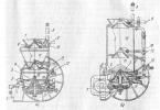
First, we will consider the device and principle of operation of a household pumping station.

Legend in Fig. 1-pressure line support, 2-tap, 3-check valve, 4-pressure switch, 5-water inlet (Silverjet does not have), 6-pressure line, 7-pump, 8- main filter, 9-suction line , 10-pumped storage tank, 11-water, 12-check valve with a mesh, 13-cover, closing the nipple, 14-hole for water drain.
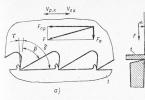
Surface centrifugal electric pump consists of from a single-phase asynchronous motor and a pumping part. The electric motor consists of a finned housing, stator, rotor, capacitor box and a fan enclosed by a protective casing. To protect the motor from overheating, a thermal relay is built into its stator winding. The pumping part consists of a casing, an impeller and a built-in ejector. Pump housing, in
Depending on the model of the pumping station, it is made of cast iron, glass-polypropylene or stainless steel. The hydroaccumulator consists of a steel reservoir and a replaceable membrane made of food grade ethylene-propylene
rubber. The accumulator has a nipple for pumping air into it under excess pressure. The pressure gauge serves to visually control the pressure in the water supply system, and the pressure switch determines the upper and lower pressure levels, upon reaching which the pump is turned off and on.
The connection of the pumping station to the mains supply is carried out by means of a cable with a plug having a grounding contact and a socket with a grounding contact. After installing and turning on the pumping station, water fills the hydraulic accumulator and the water supply system. When the water pressure in the system reaches the upper limit of the pressure switch setting, the electric pump is turned off. When you open the water tap, at the first moment of time, water is consumed from the accumulator. As the water flows, the pressure in the system drops to the lower limit of the pressure switch setting, after which the electric pump turns on again. Water enters the consumer and at the same time fills the hydraulic accumulator. When the water pressure reaches the upper limit of the pressure switch, the electric pump will turn off again. The pump on and off cycles are repeated as long as the water is drawn from the system.
For correct pumping station operation it is necessary to use a check valve with a coarse water strainer on the suction line.
Recommendations for the installation of a pumping station. On the suction line, use plastic pipes of a certain stiffness, metal pipes or hoses reinforced for vacuum (not to be confused with reinforced for pressure) in order to prevent them from vacuum compression during suction.
8.1.2. If plastic pipes or hoses are used, avoid kinking and kinking.
8.1.3. Seal well all pipe connections (air leaks negatively affect the operation of the pumping station).
8.1.4. For convenience, when servicing the pumping station, it is recommended to use quick disconnect couplings (for example,
"American").
8.1.5. The suction pipe must have at the end a check valve with a mesh (Fig. Item 12) when suction from the well, as well as, if small mechanical particles may enter, a main filter in front of the pumping station (Fig. Item 8).
8.1.6. The end of the suction pipe must be immersed in water more than 30 cm below the minimum water level. It is also necessary that the distance between the end of the suction pipe and the bottom of the tank is more than 20 cm.
8.1.7. It is recommended to install a check valve on the outlet pipe from the pump (Fig. 1, item 3) to prevent water hammer at the moments of switching on / off the pump and a valve (Fig. 1, item 2), the setting of which is described in paragraph 12, b. For Silverjet, provide for the possibility of filling water into the pump, since there is no filler hole.
8.1.8. Reinforce the pumping station in a fixed position.
8.1.9. Avoid many bends and taps in the system.
8.1.10. When suction from a depth of more than 4 meters or in the presence of a horizontal section longer than 4 meters, use pipes with a large diameter to improve the operation of the pumping station.
8.1.11. Protect the pumping station from running dry. If there is a risk of running the pumping station without water, contact your dealer for advice.
8.1.12. Ensure that water is drained from all points of the system if it can freeze in winter. To do this, provide for drain taps, paying attention to check valves that may be in the system and prevent water from draining.
Fixing the pump
9.1. The pump must be installed on level ground, close to the water source.
9.2. In the room (pit) where the pumping station is located, it is necessary to provide ventilation to reduce humidity and air temperature (max. Air temperature 40 ° C).
9.3. Locate the pumping station, observing a minimum distance of 20cm from the walls to ensure access to the pumping station when servicing.
9.4. Use pipes of the correct diameter.
9.5. Mark holes for mounting the pumping station on the surface on which it will be installed. Drill the holes to secure the pump.
9.6. Check that the pipes do not experience mechanical stress (bending), then tighten the fastening screws.
Read more about the selection and installation of a pumping station for autonomous water supply to a summer cottage or a private house.
Pumping station device

|
1001 Pump housing 1002 Bolt 1003 Bolt 1004 Gasket 1005 Nozzle 1006 Ejector gasket 1007 Diffuser J Ejector 1008 Impeller guard 1009 Lock nut 1011 Impeller 1012 O-ring 1013 Mechanical seal |
1014 Mechanical seal 1015 Front engine cover 1016 Bolt 1017 motor bearing 1018 Rotor 1019 Pin 1021 Engine housing 1022 Stator 1023 stator winding 1024 Engine support 1025 Wire 1026 Washer 1027 Engine cover, rear |
1028 Bolt 1029 Fan 1031 fan cover 1032 Terminal box cover 1033 Terminal block 1034 Capacitor 1035 Bolt TPT1-24 CL Horizontal TPG - P Pressure Gauge TPS2-2 Automatic pressure switch M Membrane TFH50 Hose with 1 "thread (50 cm) |
The main causes of malfunctions and repair of the pumping station
1. The engine does not workNo supply voltage, fuse blown, impeller jammed.
Check the wiring diagram of the pumping station. Clean the pump. Turn the fan impeller, if it does not spin, the engine is faulty (jammed). Do not turn on the station until the cause is eliminated.
Check the contacts of the pressure switch. Check capacitor.
Before starting to repair the pump, it is necessary to drain the remaining water from it and disconnect all connected devices: expansion tank, pressure switch, pressure gauge and others.
A diffuser and a guide are installed in the housing, which are interconnected.
If the cause of the hydrophore malfunction is the breakdown of these parts, then you just need to replace them with new ones and assemble the hydrophore in the reverse order.
If the reason is not in them, then it is necessary to look for a malfunction in another part of the pump.
The back of the pump consists of the electric motor itself, on the shaft of which an impeller is installed - the main mechanism that allows the pump to pump water. The motor is attached to the console, and a special ceramic oil seal prevents water from leaking through the shaft. After removing the impeller, you will have access to the oil seal.

2. The engine is running, the station does not pump water
There is no water in the pump of the station. Air has entered the suction port. Suction or supply line clogged. The station works "dry"
Check the position of the water level. Eliminate all leaks in the pipeline. Clean the suction line. Long horizontal piping can create an air lock in the middle of the pipe. It is necessary to fill the entire pipeline with water (possibly under pressure) to remove the air lock. To exclude this, the horizontal section of the pipe should always be with a slight slope towards the water intake. Eliminate the causes of dry running
3.insufficient water supply
Air is trapped (for example, the level in the well has dropped below the intake pipe), the pump or pipelines are clogged. Air in the suction line.
Clean the pump and lines. Eliminate leaks. Even a small air leak leads to the station inoperability.
Perhaps a crack has appeared on the details of the inlet pipeline structure (corners, American) as a result of corrosion. Replace damaged fittings.

4. The station turns on and off too often
The expansion tank diaphragm is damaged. Lack of compressed air in the expansion vessel or low pressure. The non-return valve is open due to blockage by a foreign object.
Replace diaphragm or expansion vessel. Again, corrosion can lead to cracks in the tank body. Pump air into the expansion tank and check the pressure with a pressure gauge. Unlock the non-return valve.

5. The station does not create a nominal pressure
The pressure switch is adjusted too low. Impeller or flow line blocked. Air ingress into the suction pipe.
Adjust the pressure switch. How to adjust is described below. The inlet of the pressure switch may be clogged - clean.
Disconnect the power supply, dismantle and clean the pump or flow line. Check the tightness of the connections on the suction line. Check that there are no elbows in the suction line or
reverse angles.

6. The station works without shutting down
The pressure switch is set too high.
Adjust the pressure switch.
If you are interested in repairing a pump such as Kid, Aquarius, Streamlet, Neptune, Chestnut - a detailed description.
Pressure regulation
If incorrectly adjusted, the pump will not turn on or will work without shutting down. Therefore, without urgent need, you should not change the settings of the pressure switch. The case of “incorrect operation” of the pumping station due to self-incorrect adjustment of the pressure switch is not guaranteed! And also the product is removed from the warranty if the components of the pumping station are out of order due to improper self-regulation of pressure. If it is necessary to change the pressure in the water supply system, you can change its limit levels by adjusting the pressure switch.

Before changing the switching pressure of the pumping station (lower working pressure), it is necessary to adjust the air pressure in the accumulator. Before that, it is necessary to disconnect the pumping station from the mains and drain all the water from the accumulator. The air pressure in the accumulator is regulated through the nipple by a car pump with a pressure gauge or compressor. The air pressure in the accumulator must correspond to 90% .. 100% of the required pressure for switching on the pumping station.
The pressure switch of the pumping station is set to operate the system in the operating pressure range of 1.5 ... 3 atm. To change the pressure on or off the pumping station, remove the cover of the pressure switch by unscrewing the plastic screw and change the tightening force of the corresponding springs of the relay. Adjustment of the pump switch-on pressure (lower working pressure) is carried out by rotating nut P. To increase the switch-on pressure, it must be turned clockwise, to decrease - counterclockwise. Adjustment of the range between the lower and upper values of the working pressure is carried out by rotating the ΔP nut. To expand this range, it must be turned clockwise, to narrow it - counterclockwise. After changing the settings, the station should be connected to the power grid, which was previously filled with water. Pressure control is carried out by the pressure gauge of the pumping station.
ATTENTION!
When adjusting the pressure switch, the upper value of the working pressure of the system should not exceed 95% of the maximum possible pressure at the outlet of the pumping station specified in the technical specifications. V
Otherwise, the electric pump will work without shutting down, which will lead to its early failure.
Also note that pumping station hydroaccumulator requires periodic maintenance. The water always contains a small part of the dissolved air, and this air gradually reduces the usable volume of the pear (rubber membrane) in the accumulator. Large-capacity accumulators usually have special valves for releasing this air, in small accumulators with which household pumping stations are usually equipped, there are no such valves, and to remove air from the membrane, a simple operation must be done every couple of months.
1. It is necessary to de-energize the pump and drain all the water from the accumulator, it is best, of course, to provide a special tap for this, or use the tap closest to the accumulator.
2. The procedure from point 1 must be repeated 2-3 times in a row.
And please do not confuse the accumulator and the storage tank for water, these are different devices, the accumulator is designed to reduce the number of pump starts, and as a result, increase its service life, as well as to protect against water hammer, if the electricity is cut off, the accumulator will certainly supply for some time water, but I would not count on much. In cases of power outages or water supply breakdowns, a storage tank is needed.