Construction stores offer us a huge range of different drilling machines in all price categories.
However, the cost of a really high-quality model hits your pocket hard, and there is no point in purchasing a cheap drilling machine from consumer Chinese manufacturers, the service life of which is ridiculous.
It is much easier to buy a good electric drill and use it to make a hand-held desktop homemade drilling machine that will fully meet all your requirements.
The cost of a high-quality drill is much less than that of full-fledged drilling machines.
In addition, you can use an electric drill that is already on the farm, since the design of the machine allows for its quick dismantling, which allows you to use one drill both in stationary and manual mode.
1 Required tools and materials
A tabletop drilling machine from a drill can be made based on metal pipes, or based on wooden parts. We recommend that you give preference to the second option, since it is much less labor-intensive and does not require the use of either an angle grinder or a welding machine.
Wood a homemade machine is durable, which is more than enough for normal household use.
You can make such a machine yourself, based on a drill, by following all the recommendations described below, with your own hands within two hours, and it will serve you for many years.
In order to make a tabletop drilling machine with your own hands, you will need the following materials:
- wooden boards 2-2.5 centimeters thick;
- metal guide rails - 2 pieces (such slats are used to supply drawers in tables and chests of drawers, they can be purchased at any furniture supermarket);
- wooden beam measuring 20*30 mm - about two meters;
- wood screws 20 and 30 millimeters long;
- wood glue;
- electric drill;
- metal rod with M8 thread;
- metal tube with M6 class thread;
- screws and nuts.

The actual work is carried out using the following tools:
- screwdriver (Phillips or regular, depending on what screws you will use);
- drill;
- sandpaper;
- jigsaw and hacksaw;
- corner;
- pencil, ruler;
- level
- roulette
- carpentry clamps for fixing boards.
1.1 Creating a base for the frame
To create a basic base for a homemade drilling machine, use a hacksaw to cut a 20*30 wooden beam into four pieces, two of which are 17 centimeters long, and two more are 20 centimeters long.
If you want to create a homemade machine based on a massive electric drill, then it would be better to make a larger base, since increasing its size will give the structure greater stability.
Next, prepare a board with dimensions of 200*220*20 millimeters (dimensions are based on the above dimensions of the timber). Using self-tapping screws, connect the beam sections into one frame. To connect at each end of the beam, you need to use two self-tapping screws; if you are using a thicker beam, you can screw in a self-tapping screw at each end corner.

Place a board on top of the resulting frame. Screw it with self-tapping screws around the perimeter of the beam; 2-3 bolts on one side will be more than enough.
To make your work easier, it is recommended Drill preliminary holes in the boards, into which it is much easier to screw self-tapping screws than into a solid board. To avoid protrusions of screw heads above wooden surface You can use a larger diameter drill to chamfer under their heads.
1.2 Creating a column for guides
The width of the board for the column must correspond to the width of the created base, the thickness is 20 mm, and the height is determined depending on the size of the drill used, as a rule, a height of 40-50 centimeters will be more than enough. An excessively high column can negatively affect the stability of the entire structure.
Once you have cut the board to the appropriate size, immediately attach it to the base using self-tapping screws. Next you need to arrange free space between the column itself and the electric drill, to do this, attach two pieces of timber, measuring 25*35*17 millimeters, in the center of the upper part of the column parallel to each other.

To avoid making a mistake with the installation location, make preliminary markings. Draw a straight line from the center point of the top of the column down, then step back 50 mm on each side and draw two lines parallel to each other. The distance between the lines should be 100 mm.
Pay close attention to so that the lines are strictly parallel to each other, so even the slightest angle of inclination of the trajectory along which the guides move risks the fact that the drill will not enter the surface being processed at a right angle, which is why when drilling hard metal surfaces, thin drills will break very quickly .
1.3 Installation of guides
Installing the guides is perhaps the most difficult part of creating drilling machine with your own hands. It is extremely important that the guides run exactly perpendicular to the base of the machine and parallel to each other.

Prepare two boards measuring 100*250*20 mm, and mark on them the places where the retractable slats will be attached. Retractable slats sold in furniture stores are already equipped with holes for self-tapping screws, so All you have to do is screw them to the guides with your own hands. After the slats are attached, we mount the guides on the column.
1.4 Creating mounts for a drill
We suggest you make a universal mount with your own hands, which is suitable for installing not only a mini-drill, but also a full-fledged electric drill. To do this, prepare a board with dimensions 60*100*20 for the upper holder, and 100*100*20 for the lower one.
Use a jigsaw to cut a hole in the center of the bottom board, the diameter of which is suitable for securely fixing your drill. Secure it to the guide using a furniture corner and self-tapping screws.

We also cut out the top holder using jigsaws. Its size and shape are individual and depend on what shape of drill you will use. We make holes around the perimeter of both clamps and screw in screws that will clamp and firmly fix the drill in the holder.
2 Making a height limiter
A height limiter is necessary so that a homemade drilling machine can make multiple holes of identical depth. Perfect for creating a limiter metal rod with M8 thread.
Drill a hole in the base in which the rod will be installed (it should be tightly fixed in the base, but at the same time rotate freely).

Next, we cut out a small piece of timber, drill a hole in it and install a threaded sleeve on one side, and a piece of rod that will limit the amplitude of movement of the guides on the other. We screw the beam onto the main rod.
For manual tabletop drilling the machine was more convenient to use, You need to make a handle on the restrictive rod.
This can be an ordinary homemade plywood stop, which is fixedly fixed between two nuts.
2.1 Making a homemade drilling machine (video)
In order to save time, you can buy a ready-made inexpensive stand and vice for a drill in the OBI.RU store, which allows you to fix the drill in a vertical position and use it as a drilling machine, thereby increasing the accuracy and speed of work.
Characteristics:
- height: 400 mm;
- clamping hole diameter: 43 mm;
- drilling depth: 60 mm;
- The set includes a vice for fixing workpieces.

Drill a hole in any material without special effort you can use for this hand power tool, such as drill, drill and screwdriver. Probably everyone has such a tool in their home workshop. But when the need arises for drilling large quantity, moreover, with great accuracy or at a certain angle, there is a need to use a drilling machine.
Drilling machines for home production can be bought in stores that sell similar equipment. Basically, this is equipment of joint production - Russia - China, for example, called Caliber, Zubr, Encore Corvette, there is a purely Chinese manufacturer. Their prices start from 7900 rubles. In principle, it’s not that expensive if you tweak the design a little, but the quality depends on how it turns out, sometimes you come across something good. There are many models produced in Switzerland - China; although they are more expensive, the reviews are good.
 Drilling machine Caliber, previously produced in Moscow, power 400 W
 Joint production means that equipment developed by, say, Russia is produced by Chinese workers. At the same time, the name, design and quality of the machine are preserved.
On such a machine, with the help of accessories, the drilling accuracy will be much higher; you can place the workpiece in a vice and drill under the right angle, the number of holes per unit time will be greater. In addition, if you need to drill holes with a diameter of, for example, 1.5 mm, you can’t do without a machine.
Making drilling machines with your own hands
If you buy a machine, then remake the stand, which in most machines is very thin and unreliable, and also constantly repair a failing spindle, it is much easier and more profitable to use a drill that you have and make a drilling machine from it yourself, using standard drawings and scheme . Of course, you shouldn’t use a hand drill, if you’re already making a machine, then it’s good and reliable, but if it’s not possible to use an electric drill, and you have a hand drill, you can use it too.

The main thing in such a machine is to firmly secure the main stand-pipe, on which there will be a support for the structure and a screw, which will be the running screw. The drill placed in the holder will move along it.
 Machine from hand drill, which can be completely assembled from wooden parts.
 Of the complex designs, we can only name a vernier scale installed with a special drum, but in extreme cases, you can do without this unit. An example of how such a simple homemade drilling machine is made with your own hands from a drill can be seen in the photo, where the author used a connecting rod to make a mount into which the drill will be attached. Also an original and at the same time simple solution for tensioning the cable.
 General form machine
  Fastening the cable according to the principle of fastening the strings in a guitar
 To make a table and attach a drill, you can use rolled metal, preferably a rectangular pipe. Of course, this is less of a machine and more of an adapter for a drill, but it does its job well.
If the machine is small, rather a mini tabletop machine that will be used for small jobs, you can make a structure for it from wood and plywood, as shown in the first diagram. During manufacturing, it must be taken into account that such components as a lever that regulates the feed of the drill and a spring that gives rigidity to the mechanism must be present in the design. If the drill is mounted for permanent use, it would be more convenient to remake the start button.
Basically, with your own hands, such drilling machines are made from drills into desktop ones, so you need to take care that the plate stands firmly and there are no distortions on it. In addition, if possible, it would be a good idea to mill out the grooves for the movement of the vice, so that along with drilling, small milling work could be carried out.
Using a powerful drill to make a drilling machine, manufacturing features
For milling in combination with drilling and for long-term drilling in metal with large diameter drills, make a drilling machine with your own hands from a drill that has high power and belongs to the class professional tools.
 A powerful drill requires a more powerful stand
 The peculiarity of using such a drill is its weight and high vibration during operation. Due to the fact that it uses a slightly larger motor, all parts are made of metal, double insulation is usually used, the weight of the drill is higher than that of household drills. Therefore, the manufacture of such a stand should only be made of metal, in addition, the table should be more massive.
 In this case there are a lot of factory parts, but for a powerful drill these parts are a godsend
 We also make the return spring more powerful, just as the cable on which the clamp works must be at least 4 mm in diameter. We also make the handles more powerful, using a rolled metal rod with a diameter of about 12 mm. For the frame, it is better to take rolled metal; it will be especially successful to use a square or rectangular pipe, perhaps 50 x 50 or 40 x 60. We take iron for the desktop at least 3 mm, welding is carried out taking into account right angle.
 Making the base for the stand
 We assemble all parts by welding or using 10-12 mm bolts. Plate in finished form should look like this:
 The base plate is finished, just needs to be painted
 Everything must be powerful enough.
 Ready stand with drill holder
  Raising and lowering mechanism
 We take the sprocket and chain from an old car, you can find it at a scrap metal dump.
Watch a video on how to make a drilling machine from a powerful drill with your own hands:
Horizontally - a drilling machine made from a drill, made by yourself.
To drill a hole, for example, inside a long shaft, using a vertical drilling machine, even a purchased one, it will not be possible to do it efficiently, no matter how hard you try. Therefore, the idea of making a machine with horizontal feed will be very useful.
Let's look at an example of manufacturing such a machine. First, we sketch a diagram and decide on the tools and materials for our homemade device.
 An example of making a stand for horizontal drilling with your own hands
 You need to have either a circular or sawing machine, drill or drill - screwdriver, hand tool, such as a chisel, hammer, various screwdrivers and similar tools.
If we make a device from wood, as in our case, we need to prepare a board, it is better to take pine and 12-15 mm plywood, a piece of chipboard. The bolts are standard, self-tapping screws, a bushing, you can take ready-made guides for furniture drawers, you can make them, a nut - an impeller, a handle, long bolts - these are like components.
You can try the following, more advanced option.
We assemble a frame from bars and chipboards, the width of the board is 20 cm, the length is about a meter. We make two guides that can be moved apart and fixed to a certain width using long fastening screws. For precise drilling, draw a line running strictly along the continuation of the drill. The table can be raised up to the desired height also with long screws. We make it from plywood and sand and polish it well before installation. The table is lifted by rotating the handle and, as it were, shifting the rectangular prisms with an oblique side towards each other. For better sliding on their sides, we stuff strips of laminate.
We install the drill in a special rack made of plywood or boards.
 Mounting the drill in a horizontal position
 A very good assembly option can be seen in this video:
According to the last example, even if you have to tinker with it, the design will be very reliable, it will be possible to withstand minimal permissible deviations and it should serve, in theory, for a long time. Since such a machine will withstand vibration due to the position of the drill, the backlash in the connections will not increase.
Everyone good day! I decided to do something wooden handles for your tools - files, chisels, cutters. I began to figure out how to make them. Planing is simply too tedious, and it turns out ugly. That would be a wood lathe! And then it dawned on me. Why not? The main idea came straight away, the details came later. I want to show you what happened as a result and tell you how I did it.
Materials and tools I used
So, to make the machine I needed the following materials:- a board made of multilayer plywood, about 10 mm thick;
- a wooden block with a rectangular cross-section 35x50 mm or 40x60 mm, about 1 meter long;
- furniture driven nut – 4 pieces (thread size is the same as that of studs);
- two threaded rods M6 - M10 plus three ordinary nuts for them and two bolts;
- a screw clamp, its length should be sufficient to clasp a hand-held electric drill with a margin;
- wood glue, self-tapping screws.

Making a lathe from a hand-held electric drill
We begin work by making the machine frame. To do this, I cut a board from multi-layer plywood 60 centimeters long and 11 - 12 cm wide. I’ll immediately make a reservation about the dimensions. Variations are possible here. But you shouldn’t make the frame too long, since the machine will be quite light, and working with long parts will not be easy.
An important point is the ratio of the width of the plywood frame and the dimensions of the block. It will be good if the width of the plywood board can accommodate three bars with the smaller side of the cross section (you will understand why this is so later). So, if the block, like mine, is 35x50 mm, then the width of the frame should be about 11 cm or a little more. If you take a 40x60 mm block, then the frame is made 12 cm wide.

So, I sawed out the base of the frame 11 cm wide and 60 cm long. After that, I sawed off a block along the length of the base, that is, also 60 cm. I cut the second block along the length of the drill body in such a way that it would not reach the chuck and subsequently not prevented him from rotating.


Using wood glue, I connect the bars with their smaller cross-sectional sides so that their ends are on the same line. I clamp the parts to be glued with clamps and let the glue harden. Our electric drive will be attached to this part of the frame, so, placing the drill on a short block, I mark the place for the hole for the clamp. I drill a hole into which the existing clamp can fit. In my case the diameter is about 10 mm.


Next, I mark a plywood board to place in the middle of its width a structure of two glued bars - long and short. Along the middle line of the board, I drill 7 - 8 holes for self-tapping screws evenly along the entire length.

Having attached the glued bars with clamps to the plywood base, I deepen the holes by drilling the block. Now I insert the screws and tighten them. The machine frame is ready.

After this, we proceed to the manufacture of the tailstock of the machine and the movable stop for the cutter. The headstock will hold the rotating part on the side opposite to the drive. It must move along the frame and be fixed in the desired position depending on the length of the clamped part. The cutter stop must also move freely along the workpiece. To make them, I used scraps of the same plywood and timber.


The movable base of the tailstock is a U-shaped structure made of two bars and a plywood rectangle. To the surface plywood base using self-tapping screws, we fasten a plywood square of double thickness, obtained by gluing two square pieces of plywood. A centering bolt for clamping the workpiece will be secured in this square. I attached a single plywood rectangle with screws and glue to the bars. The result should be a structure that moves freely along the frame guide bar.


Let's move on to the electric drive side. We fix the electric drill using a screw clamp on the frame block. To clamp the workpiece we need a threaded rod and nuts, regular and furniture driven. Holding the pin in the drill chuck, mark the required length (4 - 5 cm) and cut it off.


We sharpen the end of the hairpin using sandpaper and a drill together, clamping a piece of the hairpin into the chuck. The end of the pin must be very sharp as it will have to go into wooden blank, centering it. Next, we modify the furniture nut by turning its pointed clamps 180 degrees with pliers. This part will be used to clamp the part and transmit torque from the electric drill to it.


We assemble the structure by screwing the nuts onto the stud. The sharp end of the pin should protrude a little further (1 - 2 mm) than the sharp fasteners of the furniture nut. This will make it easier to center the part. On the reverse side, the furniture nut is fixed with a regular one. We clamp the free end of the pin into the drill chuck. If necessary, adjust the position of the drill, achieving parallelism between the stud and the frame block.
Now you need to move tailstock to the drive stud to determine where to attach the second centering bolt. We move the glued plywood square to the pointed pin, apply a light blow with a small hammer to its back side and get the required mark from the sharp pin.


We drill a hole of such a size that the sleeve of the second furniture nut fits into it. We do not modify it, but use it in normal mode, inserting the bushing into the hole and hammering the fasteners in with a hammer. If necessary, tighten the nut in a vice. We sharpen the second pin, screw it into the furniture nut on the tailstock and secure it with regular nuts. Having moved the headstock to the drive, we check and, if necessary, correct the alignment of the studs.
Similarly to the tailstock, we assemble the base of the stop for the cutter. The difference is that the plywood shelf of the stop protrudes from one side. We will screw a block here with self-tapping screws, on which the cutter will rest.
It is advisable to make a drilling machine with your own hands in situations where there is a need to drill holes in parts in a home workshop or garage various configurations, as well as made from different materials. It should be noted that such a device makes it possible to obtain holes with sufficient high level quality.
When you need a homemade drilling machine
In production or repair enterprises, where the drilling operation is considered the most common, it is used to perform it. special device, models of which may have different functionality. So, it can be a compact tabletop drilling machine, distinguished simplest design, or equipment equipped with several working spindles and numerical control.

For drilling holes in various materials, which is performed in a home workshop or garage, you can use home-made equipment. Naturally, for use at home you need a simple device that can be made from components and materials found in almost any garage or home workshop.
And in this article we will not leave unanswered the question of how to make a drilling machine at home, while spending a minimum of money. The drawings and experience of many craftsmen who have already walked this path will help us with this.
The need for such mini drilling equipment for metal, wood or plastic most often arises among those who are accustomed to independently performing various renovation work in your house or apartment. Also, quite often radio amateurs are puzzled by the construction.
It would seem that a conventional drill can be used to perform such an operation, but such a tool is not always able to provide the required quality and accuracy of drilling operations. Homemade, in addition to its compactness, has one more important quality: It can accommodate different types of drills.

Drilling machine from a conventional drill
To make a small but functional drilling machine for your home workshop, you do not need to purchase special materials and components. The design of such a convenient and useful desktop device contains the following components:
- the base, which is also called the bed;
- a mechanism that ensures rotation of the working tool (a conventional drill can be used as such a mechanism);
- device for providing supply;
- a vertical stand on which the rotation mechanism is fixed.

The stand on which the drill will be mounted can be made from a sheet of chipboard. This material is quite capable of supporting the weight of such a device. The bed of such a mini-machine should be more massive, since it protects the entire structure from vibrations, which can negatively affect both the quality and accuracy of the resulting hole, and the comfort of work.
As a material for the frame, you can use ordinary furniture board, the thickness of which is more than 2 cm. It is most convenient to use the base of an old photographic enlarger for this, slightly modifying its design. Sometimes an old microscope is used, but this is a rather rare option, since such a unit will not be large enough and its use will be limited.

The quality and accuracy that a homemade drilling machine will provide depends primarily on how correctly and reliably the connection of its base and vertical stand. The important elements of such a micro machine are two guides along which the block with the drill attached to it will move. Such guides are best made from two strips of steel, which must be securely screwed to the rack using screws.
When making the block, it is advisable to use steel clamps that will securely fix the drill on it. In addition, in order to avoid unwanted vibration processes when drilling, a thick rubber gasket must be installed at the junction of the block and the drill.
After this, you need to make a feed mechanism for such a mini machine, which should ensure the movement of the electric drill in the vertical direction. The manufacturing schemes for such a mechanism may be different, but it traditionally contains in its design a lever and a spring, which is attached at one end to the stand, and at the other to the block with the drill. This spring gives the feed mechanism greater rigidity.
A drilling machine made from a drill, which is not planned to be removed from it, can be made more convenient to use if you disassemble the original switch of the drill and mount a separate button on the frame of the mini equipment. This button will always be at your fingertips and will allow you to quickly turn the device on and off. As you can see, it’s not at all difficult to make a drilling machine from a drill; all you need to do is read these instructions carefully or watch the training videos in this article.
An example of a drill machine in more detail
As an example, let's look in more detail at one of the options for a homemade drill assembled at home.

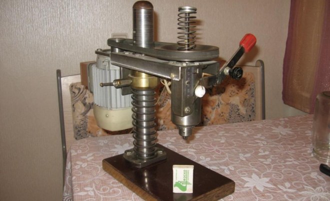
Manufacturing a machine using an asynchronous motor
Lack of excess electric drill- this is not a reason to abandon the idea of making a drilling machine with your own hands. Any electric motor can be used to drive the rotation mechanism of such equipment. Such engines, which were previously installed on various techniques, will probably be found in the garage or workshop of any home craftsman.
Asynchronous motors, which are equipped with washing machines. If you have such a motor, you can confidently use it to make home drilling equipment. Making drilling equipment with such an engine at home is somewhat more difficult than using a drill, but the power of such a machine will be much higher.
Considering the fact that the weight of an asynchronous motor is greater than the mass conventional drill, you will need a stronger base and stand to accommodate the feed mechanism.
In order for such a mini drilling and attachment machine to vibrate less during operation, it is necessary to install the motor on a powerful base and place it as close to the stand as possible. But here it is important to maintain the correct distance, since the convenience of installing the belt drive depends on it, due to which the rotation from the motor will be transmitted to the drilling head.
In order for you to make such a machine at home, you will need the following structural elements:
- gear;
- a hexagon on which the pulley will be placed;
- two bearings;
- two tubes, one of which must be with internal thread;
- clamping ring, which must be made of durable steel.
The hexagon also connects to a metal tube, bearing and clamping ring. Such a connection must be very reliable so that the resulting assembly does not collapse during operation.
The mechanism necessary to ensure the feed of the tool in such a mini machine must consist of a tube on which cuts are first made, and a gear. The tube will move due to the connection of its teeth with these cuts. An axle with a hexagon is then pressed into this tube, the height of which must correspond to the amount of the required tool feed.
A home drilling machine (simply a drill) is equipment that anyone who has ever made anything feels an urgent need for. Craftsmen sometimes make drilling machines with 2-speed gears, workpiece tables with more than 3 degrees of freedom, and even two-axis CNC drilling and milling machines, see fig. below. But in this publication we will look at making a drilling machine with our own hands - one that simply drills and mills - but accurately, cleanly, and confidently maintains its accuracy for a long time, subject to occasional short-term overload: stable processing accuracy is the main requirement for metal-cutting equipment. Which in amateur designs is carried out, unfortunately, most often only due to a random coincidence of circumstances.

Metal or wood?

Wooden drilling “machine” monster
Beginners always think that woodworking is easy and simple. The spoiled workpiece will be suitable for small crafts or fuel. Perhaps that's why in Lately There is a real fad: homemade machines with those responsible wooden parts. As a result, monsters are sometimes born that would probably surprise even Archimedes, see fig. on right. However, remember: the best achievable accuracy on wood is +/- 0.5 mm. In metal cutting, the default maximum permissible error is 0.375 mm (in England and the USA 0.397 mm = 1/64 inch). This concludes the question about using wood as the main construction material the machine is closed without discussion, saying that wood is also orders of magnitude lighter than metal and is deformed, worn out and damaged. Well, for lovers of deep inner self-satisfaction in products - free will for their money and work.
Drill device
Fantasy an indispensable condition any creative success, but in mechanical engineering it is useless without accurate calculations and comparison with solutions proven by experience. The history of machine tool construction goes back thousands of years - foot-operated bow lathes and drilling machines were used already at the end of the Stone Age. On the topic of this article, a proven sample is an industrial-style desktop vertical drilling machine. We will refer to it when choosing and deciding how best to make a drilling machine with our own hands: there are only a few examples of drilling machines in use that are over 100 years old, and they still maintain accuracy.
The structure of a desktop vertical drilling machine is shown in the figure:

Its main modules are a bed, a column, a console and a table for a part. The components of the main nodes are slightly highlighted in color, and their components are brighter in color. The simplest table(not counting the wooden block) - a vice. The rotary-sliding table allows, in addition to drilling, to perform some milling operations. The bed is usually tightly attached to a workbench or other reliable support.

Screw clamp – clamp of the mini-drilling machine console
In operation, the console is installed in the required position in accordance with the size and configuration of the workpiece using the lifting and rotating mechanism of the slider, and is fixed. The spindle is fed into the working stroke by a separate feed mechanism. In amateur and industrial designs for home use, the lifting and turning mechanism is most often the operator’s hand, and the lock is a screw clamp of the slide, see fig. on right; According to TB, both are acceptable. But what must certainly be in the design of a drilling machine according to the requirements of the same safety regulations is a bumper device or just a bumper: if you throw the feed handle, the spindle or carriage along with it should automatically bounce up until it stops. In home drills, the chipper is most often a spring installed in a suitable place, see below.
Note: industrial production, the sale and use at enterprises and workshops of individual entrepreneurs of drilling machines without a fender device is prohibited by PTB.
Make or buy?
An electric drill is a ready-made drive, gear, spindle and chuck in a monoblock. Place it on the carriage of the machine and you can drill. In terms of accuracy, the solution, generally speaking, is not optimal (see below), but in many cases it is acceptable, but eliminates the need to order expensive turned parts of increased accuracy, see below. In view of this, frames for installing drills are now sold only on the street from trays; prices are affordable. When choosing one to make a drilling machine from a drill, be guided primarily by the operating mode of the equipment; The price also depends on it:
- Occasional drilling/milling for yourself with the accuracy of what you get - cast plastic bed or stamped steel. The feed mechanism is lever with a cranked lever (see below). Carriage sliding bearings (see below) are steel on steel or with nylon liners. Prices are $20-$30.
- Regular drilling for yourself or to order with ordinary machine-building precision. The materials processed are up to the hardness and toughness of ordinary structural steel. Everything is the same, but the sliding bearings are steel on steel (worse) or with bronze bushings, and the frame is cast iron or (more expensive) composite, also vibration-absorbing. Prices: $30-$40.
- Regular drilling and milling of any materials that can be tooled with periodic overloads of the tool and/or with increased accuracy - plain bearings are only bronze on steel, cast iron frame. The feed mechanism is rack and pinion (see below); vibration-absorbing console. Prices – $60-$180.
Note: As a rule, drill beds are optionally offered with a rotary-sliding table for the part, which allows for certain types of milling. Price within $20.
Choosing a bed
The stand for the drill (which sellers for some reason stubbornly call stands) should not be selected according to the manufacturer (“China” is not “China”); Now the market is full of “German China”, not to mention products from post-Soviet states. The design needs to be checked.
First, samples with plastic non-nylon liners for sliding bearings are definitely rejected: runout and drill drift of more than 0.5 mm will appear already at the 10th - 20th “hole” and will further increase. The second is console play. We take it by the far end, swing it up and down and to the sides while holding the latch. There should be no noticeable “chatter” (the tactile sense of an untrained person feels a beat of 0.4-0.5 mm).
Next is an inspection of the structure, see Fig. below. For regular drilling, the one shown in pos. 1. Perfect option– on pos. 2: collet clamp of the drill, shifting the column to the side reduces the vibration of the console by an order of magnitude, and by turning it sideways by 45 degrees, you can mill the part by hand with the precision “as best you can” on a standard fixed table, removing a couple of table fasteners, because in this case, its manual displacement relative to the horizontal working axis of the console will be linear.

And here is a sample for pos. 3 do not take under any circumstances. Firstly, the collar of its column is low and its fastening is unreliable. Secondly, longitudinal grooves under the table facilitate manual milling “as it happens,” but, unlike diagonal ones, they do not dampen vibrations of the bed. Moreover, they will concentrate where shown by the arrows (the tide under the column is made too narrow) and from there they will go straight into the column and table.
Which is cheaper?

Let’s say the price for the machine you like doesn’t suit you. Or a drill, if it’s a “crawbar” one, with an impact mechanism, which was previously used building structures and the beating of the cartridge is visible to the eye. Then the first thing we do is find out if there is a craftsman within reach who owns a lathe with high precision (no rougher than 0.02 mm). Which, by the way, is not a fact - a high-precision machine is very expensive and never pays off with the flow of regular orders. But let's say he was found. We take the drawing in Fig. on the right, we go to him and ask if he can turn it out of steel no worse than 30KhGSA, and how much he will charge for the work. “This” is the drawings of the tabletop drill spindle. The rest of its details can be turned on on a regular machine, or found in ruins at an iron bazaar or in your trash. Most likely, it will turn out that it is cheaper to buy a bed + table, and if you estimate the costs for the rest, then perhaps a drill of increased accuracy will emerge. There are some of these on sale; they can be recognized by the absence of a striking mechanism and a collar specifically for installation in the frame: a turned steel cuff is put on it.
If you do anyway
However, there may be cases when a homemade drilling machine will either be cheaper or completely free, or the best drill on the bed will not replace it. The fact is that, in addition to bending and vibration loads, torsional loads from the working tool (tool - drills, cutters) are also transmitted to the column. This is due to the difference in the lever arms from the axis of the column to the nearest and far edges of the tool; the torsional loads from a cutter gnawing the material with one edge are an order of magnitude greater than from a drill. Therefore, it is unrealistic to achieve a machining accuracy of more than 0.1 mm with a drill on a bed (see below for why), but let’s say a hole of 2.7 is needed for an M3 thread; under M2.5 – 2.2, and the processing error in this case turns out to be unacceptable. In general, making a drill with your own hands makes sense, despite the costs, if:
- You are a radio amateur and work with components with pin pitches of 2.5 and 1.25 mm (“millipedes” with a pitch of 0.625 mm are mounted only on a plane). Then you need a drilling machine for printed circuit boards with an accuracy of no worse than 0.05 mm;
- You do other fine wood and metal work. For example, make a beautiful elegant box or reliable hiding place in the house, using only hand drilling is impossible;
- You drill/mill from time to time for yourself and the accuracy will suit you, but the stash is full of all sorts of junk metal.
Note: in the latter case, you are lucky, suddenly there is an old children's bicycle lying around somewhere. Its frame tubes are of excellent steel, and the wheel hub is almost a finished spindle; The only option available to order is an adapter with a Morse taper for a tool chuck. Working thoughtfully and carefully, an old bicycle can be turned into a drill press with an accuracy of approx. 0.1 mm, or actually a free drill stand, see for example. video:
Video: DIY drill stand
Layout
But let’s say we need higher accuracy, and we need to mill the grooves without losing it. In this case, the layout of the machine becomes of paramount importance.
The best option is to locate the spindle and drive on opposite sides of the column, pos. 1 in Fig. The heavy motor in this scheme acts as a counterweight to earthquake-resistant buildings: it reflects vibration and torsional loads from the spindle in antiphase. In the region, the columns partially cancel each other out. The damping is maximum if the center of gravity of the carriage is exactly along the axis of the console, and the higher, the thinner the drill and the less pressure on it. That is, the accuracy of the machine in delicate work increases, and at the same time, it can withstand quite significant overloads without losing it.

Note 4: it is possible to make a drill for precise work with a direct drive to the spindle and the location of it and the drive on one side of the carriage if there is a ready-made vibration-damping frame, for example. from an old microscope (under 2), etc. optical devices.
In mini machines for printed circuit boards and jewelry work, an unpleasant effect is observed: in order to obtain an accuracy above 0.05 mm, the column has to be made disproportionately thick, pos. 3. This is due to the fact that its ability to absorb vibrations and torsional loads is determined by the cross-sectional area, which decreases squarely as the size of the part decreases. For circuit boards for components with a pin pitch of 2.5 mm, as well as minor metalwork and carpentry work, an accuracy of 0.05 m is sufficient. In this case, the main influence on its deterioration is exerted by column bending loads. To fend them off, it is enough to use a double column made of a 10-14 mm bar made of ordinary structural steel, pos. 4. If enough normal accuracy 0.375 mm, then by doubling the column a drilling machine for occasional work can be made even from a drill and water pipes propylene pipes, pos. 5. Its service life before loss of accuracy is small, but the material is cheap and does not require custom processing.
Innings
The design of the spindle feed mechanism (carriage in a drill machine) also plays an important role in drilling accuracy: jerks and/or uneven feed force at least increase drill runout. When drilling with a thin carbide drill, in this case, it is very likely that it will slip, break, and, as a result, irreparable damage to the labor-intensive workpiece.
In machines and stands for high-precision drills, a rack-and-pinion feed mechanism is used (on the left in the figure), ensuring its complete uniformity and, which is especially important for manual feed, exactly proportional impact of the tool stop in the hand. This requires a rack and a gear-tribe with a well-defined tooth profile - involute. Otherwise, the feed will be jerky even with absolutely smooth pressure on the handle. It is unrealistic to make a rack-and-pinion pair with identical involute teeth “on the knee”; Finding a suitable ready-made pair is unlikely, so rack-and-pinion feed mechanisms are extremely rare in homemade drills.

More often they make a simple single-lever feed mechanism, in the center in the figure, but this is far from optimal. At the beginning and at the end of the working stroke, when the smoothness of the feed and the accuracy of drilling are especially important, it does not transmit enough emphasis to the hand, and in the middle of the stroke it is excessive, which increases the likelihood of the tool getting stuck in viscous material. The feed mechanism with a cranked breaking lever on the right is free from these shortcomings; in addition, it additionally dampens console vibrations. The knee shoulder ratio is taken to be approx. 1:1.
Serving table
Drilling of thin fragile/ductile parts is more accurate, and the likelihood of the drill leaving and breaking is less if the spindle is fixed motionless and the table with the part is moved upward towards it, therefore, in many drilling machines for fine work the table is equipped with a separate feed mechanism. Due to the inertia of thinking, it is often also made rack and pinion, see for example. Further. But, taking into account that the mass of the table in this case is much greater than that of the part, a table with a lever feed turns out to be no worse, but completely accessible for manufacturing at home. Its device is shown in the figure:

There is only one nuance: to prevent the cage from moving during assembly, it is tightly inserted into the through hole of the base and welded from below (from the bottom). You need to cook with an OMA-2 electrode or thinner with a direct current of 55-60 A using short, diametrically opposed clamps (“poke”). Table dimensions for printed circuit boards and jewelry work are 60-150 mm in diameter; thickness 6-12 mm. Table shank diameter 12-20 mm; length per feed stroke +(20-30) mm. It is advisable to machine the tube for the shank (wall thickness from 1.5 mm) or drill it and pass it with a reamer so that the shank moves smoothly in it without noticeable play. The short lever arm is made to be approx. equal to the diameter of the table; long - whatever you want.
Console
Let's look again at Fig. with factory frames. The designs of their consoles with half-frame carriages are similar; they are quite rational, but are designed for automated and robotic production: precision casting and then finishing on site on a CNC unit with laser measurement.
A diagram of an analogue console with an amateur-made half-frame is shown on the left in the figure:

The first thing that attracts your attention is that you need to cut out 5 parts from thick steel sheet, trimmed (processed end mill) for evenness and parallelism of the sides. Second, the end cuts of inserts filled with dark gray must also be smooth, clean, and parallel. Those. and here you can’t do without a milling machine. Finally, outside production conditions, it is unrealistic to perform a sliding mating between the slider and the guide carriage (shown by the arrow) with a backlash of less than 0.1 mm. Let's estimate the ratio of the lever arms - the transverse runout of the drill turns out to be more than 0.5 mm.
The design of the console of a drilling machine, which is not technologically advanced in mass production, but is adapted for production using artisanal methods, is shown on the right in Fig. (the feed mechanism and drive with bracket are not shown). Moreover, in it, the runout of the drill on inhomogeneities of the material causes the carriage on the column and the guide to skew in opposite directions, and the lateral movement of the tool does not exceed the amount of play in the sliding liners. Only one part is cut out of a thick plate - slider 4. Its precise processing is necessary only in the area of clamping the column and installing the guide, and 3 bronze bushings-liners will be precisely adjusted in place by any turner of average qualification, if you give him a column and a carriage guide (they can be machined with normal precision).
To prevent the entire assembly from welding, you need to cook it as before. case: electrode OMA-2 or thinner, direct current up to 60 A. The seams are also welded alternately with tacks: a “poke” on one, the same on the same distant one, located symmetrically. Then tack the seam closest to the first, the same on the diametrically opposite one, etc., etc., until all the seams are welded.
Note: The accuracy of a machine with the described console will be higher if it is assembled not by welding, but by screws and gluing with high-strength metal glue (cold welding). First, everything is assembled without glue, the clips are checked for parallelism and the fasteners are tightened. Then the screws are turned out one by one, glue drips into the socket and screwed back tightly. It’s a tedious task, but in this way it’s possible to get a homemade drill with a drill runout of less than 0.02 mm. Unless, of course, the spindle and chuck are centered just as well.
Errors in design
All efforts to make a drilling machine with your own hands will go down the drain if fundamental errors were made during its design. The most common of them are shown in the figure:

Typical mistakes when making a drilling machine
Pos. 1 – is this a console or what? This frame will not withstand the normal load from the tool stop for long. There is no need to talk about accuracy. Pos. 2, in addition: it is impossible to make the column of the drilling machine tubular. The pipe can withstand bending loads, but is powerless against torsional loads, and only increases vibrations.
Pos. 3 – the temptation is great to make a drill from an old photographic enlarger, especially since it is made with at least initial, but optical precision. But! The magnifier rod holder is not designed to support the tool. As a result, when drilling hardboard, the drill drift at a feed rate of 20 mm reaches 1.5 mm (!). And the bracket is made of silumin: this material does not absorb vibration, gets tired quickly, and the bracket breaks in less than the 200th hole, even when drilling printed circuit boards.
Pos. 4 – doubling the column in the transverse direction does not give anything. The resistance of the machine to loads will be no higher than on a single pin of the same diameter. Pos. 5, in addition: a rebound spring that is asymmetrical relative to the axis of the column does not dampen vibrations and torsional loads, but enhances them. Since this is the case, it was necessary to install 2 identical springs on both racks. It would be better to make a column, as shown here:
Video: do-it-yourself drilling machine from a drill
Pos. 6 – installation of the drive and spindle on one side of the column, and even asymmetrical, does not reduce, but increases vibrations, because they are transmitted to the column in phase, see above. Pos. 7 – where is the bump stop? Yes, it cannot be here, since the feed drive is screw. Using a screw, you can accurately adjust the slider (which is not here at all), which on home machine in general, it’s not necessary, but under no circumstances should you feed the carriage! This structure will almost throw fragments of drills and shavings, and the operator’s eyes will be in close proximity to the danger zone.
Analysis of structures
Examples of successful technical solutions, as well as not so significant design flaws, we will consider the examples of several homemade drilling machines.

For a radio amateur, modeller, miniaturist and/or jeweler, a simple mini-drilling machine with direct drive may be of interest (the drawings are given in the figure on the right). The design feature is that the drive motor is rigidly attached to the slide, and the feed is only from below the table. The massive electric motor itself serves as a vibration damper and torsional load absorber, just like an anti-seismic load on high-rise buildings. Thanks to this, all parts, except for the Morse taper with an adapter on the motor shaft, can be performed with ordinary precision: the drilling accuracy is determined by the runout of the motor shaft + the runout of the cone with the adapter + the runout of the drill itself. A table with a rack and pinion feed mechanism can be easily changed to a lever one. It is better to use a commutator engine direct current: for asynchronous motors with capacitor starting due to the unevenness of the rotating magnetic field and the rotor slips and the shaft rotates less evenly. In addition, the rotation speed of a commutator motor is well regulated by at least a simple rheostat, but to adjust the speed of an asynchronous motor, you need to change the frequency of the supply current. The same for synchronous with a magnetic rotor. The maximum rotation speed of the motor shaft is 800-1500 rpm. Power on the shaft for drilling holes up to 3 mm – 20-30 W; for holes up to 6 mm – 60-80 W.
Note: This machine is not suitable for milling, because The motor shaft bearings are not designed for lateral loads and the machine will quickly lose accuracy in this mode.
Here in Fig. Given are the drawings of a fully functional mini-drilling machine for the same purpose, also with direct drive:

It is equipped with a separate spindle, which allows, firstly, to insert a drill of a maximum diameter of 6 mm into chuck No. 1a; For 8-10 mm drills the engine is rather weak. Secondly, perform milling with dental burs. Apparently, the author of the design often uses this particular operation, based on which the motor rotation speed was chosen. Without reducing it, you need to drill on this machine with carbide drills, and to use conventional ones, add a speed controller to the design; in this case, a motor of at least 60 W is needed. The glaring drawback of this machine - a simple lever feed drive - can be easily eliminated: the feed lever is replaced with a cranked one without modifying the remaining parts. To increase the accuracy of processing, it is also advisable to install a second rebound spring (item 14 in Fig. and 9 in the specification; there is still confusion there) symmetrically to the first, at the other end of the spindle driver. A more serious design flaw is that the rebound springs do not participate in damping vibrations and torsional vibrations. At rotation speeds above 5000 rpm, their influence on accuracy is practically not affected, but already at 1500 rpm, the runout of the drill during the working stroke increases by approx. doubled.
Drawings of a mini-drilling machine, intended to be structurally complete, but with annoying errors, are shown in Fig; The design of the carriage is similar to the console in the previous one. designs.

Thanks to the installation of a strong rebound spring in the proper place, it was possible to rigidly fix the spindle in the carriage, which at first glance reduced the number of parts requiring increased manufacturing precision. But only when feeding from below with a table, and even then, fixing the slider 5 and carriage 4 with pairs of screws 17 and 16 respectively. unreliable and damages the column; It would be better to use screw clamps. And when the released carriage is fed with a lever, only its joints prevent the carriage from turning. A play of 0.02 mm in any of the lever hinges, taking into account its relationship with the length of the knee arms, will result in lateral movement of the drill by 2 mm or more, which can only be countered by hand. In this machine, the most appropriate thing would be a console with an additional carriage guide, described above; in this case, it would be quite possible to achieve tool runout due to backlashes in the mating parts of the machine itself of no more than 0.02-0.03 mm.
In this fig. – drawings of a frame for a drilling machine from a drill with a half-frame carriage, “almost like the real thing.”

Everything about it is good, and some things are even better than the “brand”: plates 5, which prevent lateral movement of the carriage, perfectly “catch” and suppress tool vibrations in their very bud. There is only one question: how to do all this if in the garage (shed) there is a machine park worthy of a small machine-building plant, waiting for the owner’s hand? It’s easier to make a drilling machine from a drill as shown in the video:
Video: homemade drill stand
I can’t help but remember an old Soviet joke:
“Dear Comrade Leonid Ilyich honored with his visit a certain industrial enterprise. They are walking through the workshop, suddenly the Secretary General stops his retinue with a wave of his hand, and one approaches the worker at the machine:
- Comrade turner...
- Yes, Petrovich I...
- Fine. Comrade turner Petrovich, tell me frankly - do you drink vodka?
- Why not! Let's use it!
– And if a bottle costs 10 rubles, will you still drink it?
- Will.
- What about 25?
- Will.
- What about 50?
- Will.
- What about 100?
- I will anyway.
- Petrovich, ... but where can I get you so much money for your salary?!
“Gee... what does the money have to do with it... this little thing (shows) how it cost half a liter, so it will cost.”
Some are happy, some are sad, but those Petrovichs, general secretaries and industrial relations no longer exist. And they won’t – they turned out to be completely ineffective.
About steering drills

A fairly popular request on this topic is also “drilling machine from steering rack passenger car" It seems to be a ready-made converter of rotational motion into linear motion, and even with a geoidal transfer characteristic: in order to “peck” a little with a drill, you don’t need to “catch microns” with your hand. You just need to adapt the steering wheel to the rack, make a drill holder (see the figure on the right), and you're done, see the video.


