At high pressure and temperature - autoclave only. In case sterilization is carried out at high temperature, but without pressure, the term sterilizer or drying cabinet is used. It was invented by Denis Papin in 1679.
Collegiate YouTube
1 / 3
✪ Autoclave equipment from the company "Original Trade"
✪ STERILIZATION OF TATTOO EQUIPMENT IN HOME CONDITIONS // Hammered Hands
✪ Opening the bur. Beautiful experiences.
Subtitles
Varieties of autoclaves
Autoclaves are: rotating, swinging, horizontal, vertical and columnar. The autoclave is a vessel, either closed or with an opening lid. If necessary, they are equipped with internal, external or external heat exchangers, mechanical, electromagnetic, or pneumatic mixing devices and instrumentation for measuring and regulating pressure, temperature, liquid level, etc.
Autoclave design
The design and main parameters of an industrial autoclave are varied, the capacity is from several tens of cm³ to hundreds of m³, and are designed to operate under pressure up to 150 MPa (1500 kgf / cm²) at temperatures up to 500 ° C. For chemical industries, if it is necessary to mix the product, as an option, autoclaves with sealless mixers and a shielded electric motor that do not require sealing are promising. The rotor of this electric motor is mounted directly on the agitator shaft and covered with a sealed thin-walled screen made of non-magnetic material that does not prevent the penetration of magnetic lines of force from the stator of the electric motor to the rotor.
In the production of building materials, tunnel or dead-end autoclaves are used. Outwardly, they are a pipe 3-6 m in diameter and 15-20 m in length, closed by a lid with a bayonet lock (dead-end on one side, tunnel on both sides).
Along the length of the autoclave, there are rails for trolleys with products. Autoclaves are equipped with lines for saturated steam inlet, waste steam bypass to another autoclave, steam release to the atmosphere or into a heat exchanger, and for condensate drainage.
In the food industry, vertical and horizontal autoclaves are used in a wide range of varieties, sizes and operating principles. For example, in horizontal autoclaves for the food industry, the necessary back pressure can be created in relation to each individual packaging with a product, which allows sterilization of products not only in rigid containers (glass jars, tin cans), but also in soft and semi-rigid packaging.
Autoclave applications
Autoclaves in the food industry
Autoclave cooking is a method of preparing food in an airtight container or autoclave that prevents air or liquid from leaving the container under high pressure. Since the boiling point of the liquid shifts upward with increasing pressure, the temperature of the liquid inside the system can be raised to 100 ° C. In this case, the liquid does not reach the boiling point. Most high pressure cooking systems operate at 15 psi operating pressure, the standard established in the USA in 1917. At this pressure, the liquid boils at a temperature of 125 ° C. The increased temperature allows the product to be cooked incomparably faster than the standard method.
For example, chopped fresh cabbage is cooked within one minute, preserving the entire vitamin and flavor range of the product. Fresh green beans or small potatoes take about five minutes to cook, and a whole chicken up to 3 kg takes about 20 minutes. Another advantage of the autoclave cooking method is that it achieves the effect of stewing and slowly boiling the product in a very short time.
Today, climbers use small installations to boil water at high altitudes. High in the mountains, water boils away before reaching 100 ° C, which interferes with proper food preparation and proper cooking, as Charles Darwin wrote in The Beagle Journey.
The autoclave method of cooking was considered highly explosive. Modern autoclave cooking systems are equipped with multi-stage safety mechanisms, special locks and automatic shutdown systems.
How the system works
Under normal conditions, water cannot be heated above its boiling point. As soon as the temperature reaches 100 ° C, the water stops heating up. This is due to the intense evaporation of water during the heating process. If the water is boiled for a long time, then it completely turns into steam.
When water or liquid is boiled in an autoclave, the boiling point rises. As soon as the temperature of the soup or puree reaches 90 ° C, intense evaporation begins. Water vapor, which is essentially a gas, creates excess pressure in combination with temperature, which causes evaporation to stop. The higher the temperature, the higher the pressure in the system. The heat generated by increasing pressure is called latent heat and has a great penetrating power into the structure of microorganisms, destroying them even in a dormant state - in spores.
A similar process is easily achieved when preparing solid, non-cavernous foods. In the case of cooking spongy, cavernous products, you should choose a system with deep evacuation of the container. The residual oxygen content can help protect bacteria from destruction by providing thermal insulation for their shells.
Modern autoclaves use fractional evacuation, which removes oxygen in several cycles, ensuring 100% steam penetration during sterilization and homogenization of the product.
Autoclave cooking allows you to cook food many times faster, while maintaining all the nutritional properties of the product.
Nutrients
Operation of industrial autoclaves
When using autoclaves, their owner is obliged to ensure the proper condition of the vessels and their working conditions. For this purpose, a trained person is appointed responsible for the good condition and safe operation of the pressure vessels.
The personnel in charge of servicing the vessels must carefully monitor the equipment assigned to it by inspecting it, checking the operation of the valves, instrumentation, safety and interlocking devices, and maintaining the vessels in good condition. The results of the inspection and verification should be recorded in a shift logbook.
In Russia, regulatory documents for the operation of autoclaves are issued and approved by Rostekhnadzor.
STATE STANDARD OF THE UNION OF SSR
AUTOCLAVES FOR THE CONSTRUCTION INDUSTRY
TECHNICAL CONDITIONS
GOST 10037-83
IPK PUBLISHING STANDARDS
Moscow
STATE STANDARD OF THE UNION OF SSR
Date of introduction 01.01.85
This standard applies to autoclaves designed for thermal and moisture treatment of silicate bricks and silicate products from aerated concrete.
The requirements of this standard are mandatory.
1. TYPES, BASIC PARAMETERS AND DIMENSIONS
1.1. Autoclaves are made of two types:
AT - dead-end;
2. TECHNICAL REQUIREMENTS
2.1. General requirements
2.1.1. Autoclaves should be manufactured in accordance with the requirements of this standard, "Rules for the Construction and Safe Operation of Pressure Vessels" approved by the USSR State Technical Supervision Service, according to working drawings approved in the prescribed manner.
2.2. Construction requirements
Table 1
Dimensions in mm
|
Working part length L |
Working pressure, MPa, no more |
Working temperature, ° С |
Nominal track gauge |
Overall dimensions with closed covers, no more |
||||
|
Length for types |
||||||||
Note. At the request of the consumer, it is allowed to manufacture autoclaves of each standard size and length L up to 41000 mm.
On a dead-end autoclave, the inner diameter of the body is allowed to be made according to the actual diameter of the bottom within the tolerance for deviations in the diameter of the bottom.
An example of a conventional designation of a dead-end autoclave for a pressure of 1.2 MPa, an inner diameter of 3600 mm, a working part length of 27000 mm:
AutoclaveAT 1,2 - 3,6 ´ 27 GOST 10037-83
2.2.1. The design of autoclaves should ensure:
Quick opening and closing of lids and sealing of their connection;
Continuous drainage of condensate;
Automatic regulation of the technological process of steaming;
Remote control of the bayonet lock and opening - closing the autoclave lid;
Fixing the lid in the open position;
Overlap along the entire length of the teeth of the cover flange and the body flange (bayonet ring) in accordance with Fig. ;
Gap difference S between the tooth of the cover flange and the cavity of the body (bayonet ring) in accordance with Fig. for any two diametrically located gear teeth - no more than 3 mm;
Freedom of axial thermal movement of the housing;
Inability to open the autoclave lids under pressure;
Inability to supply steam to an open autoclave;
Visual control of steam pressure.
2.2.2. The design of the autoclave should provide for continuous recording on paper tape of the following parameters:
Steam temperatures inside the autoclave;
The temperature difference between the upper and lower generatrix of the body in the central section.
The design of the autoclave should provide the ability to control the following parameters during operation:
The presence of condensate;
Heating and cooling rates of the case;
Thermal elongation of the body;
Steam pressure inside the autoclave;
Overlap along the entire length of the teeth of the cover flange and the body flange (bayonet ring) in accordance with Fig. ;
Differences in the clearances between the teeth of the cover flange and the cavity of the body flange (bayonet ring) for any two diametrically located teeth in accordance with Fig. ...
Bayonet gear
1 - bayonet ring; 2 - lid; 3 - frame
2.2.1, 2.2.2.(Modified edition, Amendments No. 1, 2).
2.3. Requirements for materials
Working at temperatures up to 200 ° С - from steel grade 15K or 20K of the third category in accordance with GOST 5520;
Those operating at temperatures above 200 ° C - from steel grade 15K or 20K of the fourth category in accordance with GOST 5520 with verification of mechanical properties and impact strength after mechanical aging of each sheet.
The use of steel grade 15K is not allowed in newly designed and modernized autoclaves.
(Modified edition, Amendment No. 2).
2.3.2, 2.3.3. (Modified edition, Amendment No. 2).
(Modified edition, Amendment No. 2).
Single shells and other similar defects located at a distance of St. 50 mm, not more than 5 mm each, but not more than 8 pcs. for 1 running meter;
Roughness and waviness no more than 4 mm high;
Remains of feeders and bays no more than 3 mm high;
Remains of profits with a height of no more than 4 mm.
Local surface depressions, sinks and joints with a size of not more than 4 mm are subject to cutting and cleaning.
Metallized burn-in in the form of a film with a thickness of not more than 2 mm must be stamped.
Cracks of all types and directions without correction are not allowed.
2.3.8. Defects in castings, the size and number of which are more than those specified in paragraphs. and, should be corrected by welding.
2.3.9. On castings made of steel grade 20L or 25L, defects up to ⅛ of the thickness of the part in the place of the defect and an area of not more than 50 cm2 each, located dispersed in an amount of not more than 4 pcs. on the part, it should be corrected by welding without subsequent heat treatment, and from steel grade 35L - with subsequent heat treatment. Defects up to 1/3 of the thickness of the casting at the site of the defect and an area of not more than 300 cm2 each in an amount of not more than 4 pcs. the part should be repaired by welding followed by heat treatment.
Details with defects in the depth of St. 1/3 of the thickness of the part itself in the place of the defect cannot be corrected.
2.3.11. Autoclaves should be made of materials, the quality of which must be confirmed by certificates or test results. Data of certificates or results of tests of materials should be indicated in the passport of the autoclave.
2.4. Manufacturing requirements
2.4.1. Methods for assembling elements for welding should ensure the correct relative position of the mating elements and free access to the performance of welding.
2.4.2. The manufacturer in the manufacture of autoclaves must carry out operational control.
2.4.3. On the sheets accepted for the manufacture of shells, the marking of the metal manufacturer must be preserved, and in the case of their cutting into blanks, the marking must be transferred to each blank.
2.4.4. Each workpiece or its parts must be marked with the following data:
Steel grade;
Batch number-smelting;
Sheet number.
The autoclave shells must be marked with the serial number of the shell and the designation of the working drawing.
The place of marking is the corner of the cut sheet, at a distance of 300 mm from the edges.
(Modified edition, Amendment No. 2).
2.4.5. Permissible deviations of the shell length ± 5 mm.
2.4.6. (Deleted, Amendment No. 2).
2.4.7. The deviations of the length of the sweep of the circumference of the shells should not be more than:
± 5 mm - for sheets with a thickness of 18 mm;
± 7 mm "" "20 mm;
± 9 mm "" "28 mm.
The length of the sweep is measured from both ends of the shell blank.
2.4.8. Deviations (due to any reason) in the thickness of the shell wall should not be such that its actual thickness was lower than the calculated one.
2.4.9. The non-perpendicularity of the shell end to its generatrix is allowed up to 1 mm per 1 m of diameter, but not more than 3 mm for a shell with a diameter of 3.6 m.
An edge cut with a depth of no more than 2 mm at an arc length of up to 150 mm is allowed for one of the butted shells.
2.4.10. After assembly and welding, the autoclave bodies must meet the following requirements:
Length deviation - within ± 0.3% of the nominal length of the body (without the bottom), but not more than ± 75 mm;
The deviation from the straightness of the housing should not exceed 30 mm.
Taper 4 mm - for bottoms with a wall thickness of 18 and 20 mm;
6 mm - for bottoms with a wall thickness of 28 mm (Fig. a);
The height of the corrugations on the cylindrical part of the bottom is more than 2 mm (Fig. e);
Thinning of the wall 15% of the original thickness of the workpiece and thickening of the bottom flange 15%.
table 2
|
Bottom wall thickness |
Maximum deviation (Fig. d) |
Concavity and convexity WITH(heck. b, v) |
Face runout f(heck. G) |
The gap between the template and the bottom surface in any diametrical section |
|||
|
inner diameter D v |
sphere heights h v |
||||||
2.4.17.(Deleted, Amendment No. 2).
* Heck. 6. (Deleted, Amendment No. 2).
2.4.18. On the longitudinal seams of the autoclave shells, it is allowed to install fittings with a diameter of not more than 150 mm.
At the intersections of the joints, the installation of fittings is not allowed.
2.4.19. When welding to the body of the fittings, the distance between the edge of the weld on the fitting and the edge of the nearest seam must be not less than the thickness of the body wall, but not less than 20 mm.
2.5. Welding requirements
2.5.1. Welding work in the manufacture of autoclaves should be carried out in accordance with the "Rules for the certification of welders", approved by the USSR Gosgortekhnadzor.
2.5.2. In the manufacture of autoclaves, all types of welding are used, except for gas.
2.5.3. Welding work should be carried out at a positive ambient temperature.
2.5.4. The shells, the bottoms and flanges of the autoclave body should be welded with double-sided butt welds, and the fittings should be welded with fillet welds.
2.5.5. The edges of the elements prepared for welding and the surfaces adjacent to them must be cleaned to a bare metal to a width of 20 mm.
2.5.6. Tacking of the elements to be welded should be made with filler materials intended for welding this metal.
2.5.7. Each welded seam must be branded, allowing the identification of the welder who made these seams. The stamp should be placed at a distance of 20 - 50 mm from the weld. On longitudinal seams, the stamp should be placed at the beginning or end of the seam at a distance of 100 mm from the circumferential seam. On circular seams, a stamp should be placed at the intersection of the circular seam with the longitudinal one and then every 2 m, but at the same time there should be at least three hallmarks on each seam. Brands should be placed on the outside of the autoclave.
2.5.8. The longitudinal weld seams of the autoclaves should be located outside the central corner of the lower part of the body, the value of which should be at least 75 °.
2.5.9. When welding supports or other elements to the autoclave body, the distance between the edge of the vessel's weld seam and the edge of the welded seam of the welded element must be at least the thickness of the autoclave body, but not less than 20 mm.
(Modified edition, Amendment No. 2).
2.5.10. Seams should be positioned so that visual inspection and quality control can be carried out and defects can be eliminated. Supports should not intersect circumferential welds for a length of more than 0.35 pD.
2.5.12. The displacement of the edges of the sheets in the butt joints, which determine the strength of the autoclave, should not exceed 10% of the nominal thickness of the thinner sheet, but at the same time should not be more than 3 mm (Fig.).
2.5.13. The displacement of the edges in the circumferential seams with a sheet thickness of up to 20 mm should not exceed 10% of the nominal thickness of a thinner sheet plus 1 mm, and with a sheet thickness of St. 20 mm - 15% of the nominal thickness of a thinner sheet, but this should not be more than 5 mm (Fig.).
2.5.14. Longitudinal seams of adjacent shells must be displaced relative to each other by at least 100 mm between the axes of the seams.
2.5.16. The value of the tensile strength of the welded joint obtained for each of the two samples must correspond to the tensile strength of the base metal, while on one sample it is allowed to obtain results below the established norm for the base metal by no more than 7%.
2.5.17. When testing specimens for bending, the bending angle should be at least 100 ° at D = 2S, where D- punch diameter; S is the thickness of the test specimen.
2.5.18. Welded joints of the “sheet-forging” type correspond to those of the “sheet-to-sheet” type, while the bending angle must be at least 70 °.
Fistulas and porosity of the outer surface of the seam;
Undercuts with a depth of more than 0.5 mm and a length of more than 10% of the seam length;
Sagging, burn-throughs and unfused craters;
Displacement and joint drift of the edges of the welded elements in excess of the norms provided for in this standard;
Inconsistency of shape and size with the requirements of standards, specifications or working drawings;
For joints subject to ultrasonic and magnetic particle inspection, surface scaling and sinking between the weld beads exceeding 0.2 mm in depth and 0.2 in length S, where S- nominal thickness of the welded element in millimeters.
(Modified edition, Amendment No. 2).
2.5.20. The following internal defects are not allowed in welded joints:
Cracks of all types and directions;
Lack of penetration (lack of fusion) located in the section of the welded joint.
2.5.21. In welded butt joints, when controlled by the radiographic method, the following are not allowed:
Internal single pores, slag and other inclusions with a width (diameter) of more than 0.1 S and more than 0.2 S;
- accumulations of internal pores, slag and other inclusions longer than 0.3 S.
The total length of pores, slag and other inclusions for any section of the radiogram with a length of 10 S should not exceed 1.0 S. For a smaller length of radiograms, the admissible total length of pores and other inclusions (for any section of radiograms with a length of 10 S) decreases in proportion to the length of the radiograms. In this case, the minimum length of radiograms cannot be less than 2 S.
Notes:
1. With different thicknesses of the welded elements, the maximum allowable size of defects is selected for the smallest thickness.
2. The sizes of pores and other inclusions should be taken as the following sizes of their images on radiograms:
Diameter - for spherical pores and inclusions;
Width and length - for elongated pores and inclusions.
3. An accumulation is called three or more randomly located pores and other inclusions with a distance between any two adjacent edges of the images of pores or inclusions of more than one, but not more than three of their maximum widths or diameters.
4. The size of an accumulation of pores and other inclusions is taken as its length, measured along the most distant edges of images of pores or inclusions in the cluster.
5. Pores or inclusions with a distance between them not exceeding their maximum width or diameter, regardless of their number and relative position, are considered as one pore or one inclusion.
Table 3
Notes:
1. The maximum permissible number of single defects for any 100 mm of the length of the seam of the welded joint is 3.
2. Extensive defects found on the fixation sensitivity are not allowed.
2.5.20 - 2.5.23.(Introduced additionally, Rev. № 2).
2.6. Quality control of welded joints
External examination and measurements of seams;
Mechanical tests;
Ultrasonic flaw detection;
Transillumination (gamma grating);
Hydraulic test;
Capillary or magnetic particle inspection.
2.6.2. External examination and measurement of welded seams must be carried out after cleaning welded seams and adjacent surfaces of the base metal on both sides of the seam from slag, splashes and other contaminants.
All welded joints are subject to external examination in order to identify the defects specified in paragraphs. - , and .
2.6.1, 2.6.2. (Modified edition, Amendment No. 2).
2.6.12. The inspection method (ultrasonic flaw detection, transillumination, or their combination) should be selected based on the need for a more complete and accurate detection of unacceptable defects, taking into account the peculiarities of the physical properties of the metal, as well as the peculiarities of the inspection method for welded joints of this type and products.
2.6.14. 100% of the length of all welded joints of autoclave elements operating under pressure are subject to non-destructive testing by radiographic or ultrasonic methods, while quality control of welds of permanent joints of cast parts with each other, with rolled products or forgings must be carried out by the radiographic method.
2.6.13, 2.6.14.(Modified edition, Amendment No. 2).
2.6.15. Before inspection, the relevant areas of welded joints should be marked so that they can be easily detected on inspection charts or gamma images.
2.9. Reliability requirements
12000 (14700 from 01.01.95) working cycles for autoclaves with an inner diameter of 2000 mm, except for long autoclaves with a length of 41000 mm;
11000 (12000 from 01.01.95) working cycles - for autoclaves with an inner diameter of 2600 and 3600 mm.
Upon expiration of the designated resource or detection of damage, the autoclaves must be subjected to a special technical examination to determine the possibility of further operation.
Each autoclave must undergo a technical inspection in accordance with a special provision for the inspection and repair of autoclaves, agreed with the USSR Gosgortekhnadzor, after which a decision is made on the possibility and duration of its further operation.
2.9.2. Indicators of maintainability of autoclaves:
Specific total operational labor intensity of current repairs - no more than 0.2 (0.19 from 01.01.95) man-h / cycle;
Specific total operational duration of technical maintenance - no more than 0.33 (0.31 from 01.01.95) man-h / cycle.
2.9.1, 2.9.2.(Modified edition, Amendments No. 1, 2).
3. SAFETY REQUIREMENTS
3.12. The check valve outlet must point to a safe location.
(Modified edition, Amendment No. 1).
3.15.(Deleted, Amendment No. 2).
3.16. The permissible temperature difference between the upper and lower generatrices of the autoclave during pressure rise and holding is no more than 45 ° C.
3.17. The permissible rate of heating and cooling of the autoclave body based on strength conditions is no more than 5 ° C / min.
3.16, 3.17.(Introduced additionally, Amendment No. 2).
4. COMPLETENESS
4.1. The autoclave kit should include:
Hull (with track):
Cover (for AP type - two covers);
Mechanism for opening and closing the covers (in the case of a hydraulic drive, a pumping station is supplied with each autoclave with a diameter of 2600 and 3600 mm; one pumping station is supplied for a group of autoclaves with a diameter of 2000 mm, and a shut-off valve is installed on the oil line of each autoclave);
Autoclave supports;
Rollers with anti-theft device for movable supports;
Reference device;
A set of wearing parts according to the spare parts list;
Foundation bolt set;
Remote Control;
Safety valve and pressure gauges (for a dead-end autoclave - one, for a straight-through autoclave - two);
Signal-blocking and latching device with a control valve and "Key-mark";
Continuous condensate drainage system with level indicator;
A device for automatic control of the technological process of steaming, providing a given rate of heating and cooling of the body (at the request of the consumer);
A device for controlling the rate of heating and cooling of the body and the temperature difference between the upper and lower generatrices of the body;
Walking bridge for autoclaves with a diameter of 2000 mm;
Low-voltage complete devices.
(Modified edition, Amendment No. 2).
Operational documentation in accordance with GOST 2.601;
Passport of a pressure vessel (autoclave);
A set of drawings.
4.3. Mating flanges must be attached to the autoclaves with working gaskets and fasteners.
4.4. Highly wearing parts - in the amount that ensures the operation of the autoclaves during the warranty period.
5. RULES OF ACCEPTANCE
5.1. To verify the conformity of autoclaves with the requirements of this standard, the manufacturer must carry out acceptance, periodic and operational tests.
5.2. Each autoclave is subjected to acceptance tests for compliance with the requirements of paragraphs. tab. . control systems, interlocks and alarm systems.
(Modified edition, Amendment No. 2).
5.3. Before testing for compliance with the requirements of clause regarding hydraulic tests, the autoclave should be inspected without the use of magnifying devices.
On the outer and inner surfaces there should be no captivity, sunsets, delamination, rough scratches, cracks, and on the welded seams also sagging, undercuts, cracks, pores and other defects that reduce the quality and worsen the presentation. No dirt and foreign objects are allowed inside the case.
5.4. During inspection, check the presence and correctness of marking on the shells, bottoms, flanges and proprietary plate. Check the presence of welders' marks on the welded seams.
5.5. One autoclave of each standard size is subjected to periodic tests under operating conditions at least once every three years.
The tests are carried out according to the program and methodology approved in accordance with the established procedure.
5.6. Operational tests are carried out according to the program and within the time frame established by the special rules of the USSR Gosgortekhnadzor.
6. TEST METHODS
6.1. The length, width, height, track are checked with a tape measure along GOST 7502 with an upper measurement limit of 30,000 mm and a graduation of 1 mm; the inner diameter is checked by measuring the outer circumference in terms of the inner diameter, taking into account the thickness of the sheets taken from the certificate.
6.2. Working pressure (tab.) check with a manometer in accordance with GOST 2405 with a measurement range of 0 to 2.5 MPa, an accuracy class of at least 1.5.
(Modified edition, Amendment No. 2).
6.3. Working temperature (tab.) during operation is checked using a thermocouple with the parameters of GOST 3044.
(Modified edition, Amendment No. 1).
6.4. The mass of the autoclave (table) is checked by summing the assembly units and parts included in the delivery set.
6.5. Hydraulic tests (p.) Are carried out at the manufacturer with test pressure R pr, MPa (kgf / cm2), calculated by the formulas:
For autoclaves with forged bayonet closure elements
![]() ; (1)
; (1)
For autoclaves with cast bayonet closure
![]() , (2)
, (2)
where [s] 20 - permissible stress at a temperature of 20 ° C;
[s] t - allowable stress at operating temperature;
R- working pressure, MPa (kgf / cm2).
Testing time at test pressure - not less than 10 minutes.
For hydraulic testing, water with a temperature of at least 5 ° C and not higher than 40 ° C is used. The autoclave is considered to have passed the hydraulic test if there are no signs of rupture, leakage, tears and sweating in welded joints and on the base metal, visible permanent deformations.
The rise in water pressure in the vessel is produced by a pump without jolts and shocks.
The pressure equal to the working pressure is maintained for the entire time required for inspecting the autoclave. Do not knock on the pressurized autoclave.
The rate of pressure rise during hydrotesting is no more than 0.5 MPa / min.
(Modified edition, Amendment No. 2).
6.6. Inspection of paints and varnishes (p.) Is carried out visually.
6.7. The assigned resource (item) is checked according to the data of controlled operation.
7. MARKING, PACKAGING, TRANSPORTATION AND STORAGE
7.1. Each autoclave must have a label attached to GOST 12969 and GOST 12971, containing the following data:
The name of the manufacturer or its trademark;
Autoclave index;
Serial number according to the manufacturer's numbering system;
Year of issue;
Operating pressure;
Test pressure;
Allowable maximum working temperature of the wall;
Designation of this standard.
The material, location of the plate, the method of attachment and marking must ensure its safety during the entire service life of the autoclave.
Autoclave
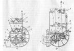
The autoclave is designed for heat and moisture treatment of products made of silicate concrete (dense and cellular). It is a cylindrical vessel with quick-closing spherical lids. The autoclave consists of the following main units: body, spherical covers with a lifting mechanism, bayonet rings with a swing mechanism, a pumping station, a distribution station, a cooling system, limit stops, contact pressure gauges and an automatic control system.
The autoclave body (Fig. V-6) consists of butt-welded shells and flanges that are welded to the body and are designed for bayonet connection of the autoclave body with quick-closing lids. The wall thickness of the autoclaves with a diameter of 2.6 m-20 mm and a diameter of 3.6 m-26 mm, the working pressure is 8 and 12.5 atm, respectively.
To seal the autoclave, a rubber gasket of a special profile is laid between the flanges of the body and the lid. T-section stiffening rings are welded on the outer surface of the autoclave body. Inside the body there are rails, along which the parking trolleys are rolled into the autoclave.
To give greater rigidity, two longitudinal beams are welded to the outer surface of the autoclave. The autoclave body is mounted on supports, of which one (middle) is fixed, and eight are movable.
The spherical cover with a lifting mechanism consists of a stamped spherical head and a flange welded to it. The cover has lugs that attach it to the lifting lever. The lifting mechanism consists of a swing cylinder, a lever, a clamp, a clamp swing hydraulic cylinder (not shown in the drawing) and a bracket on which the entire lifting mechanism is mounted.
The hydraulic cylinder is mounted on a bracket with trunnions, on which it can turn when opening and closing the lid. The swing cylinder rod is connected to one end of the lever. The other end of this arm is attached to the lid of the autoclave. In the open position, the cover is held by the hydraulic cylinder rod and additionally by a clamp driven by a special hydraulic cylinder.
A bayonet ring with a pivoting mechanism is designed to lock the autoclave lid. It consists of two half-rings connected by bolts in the center plane.
The swing mechanism includes two hydraulic cylinders mounted on brackets fixed to the autoclave body. The cover is locked by turning the bayonet ring using two hydraulic cylinders, while the tooth (projection) of the ring goes over the lip of the cover flange, thereby forming a lock.
The autoclave has a signal-interlocking device that ensures that steam cannot be put into the autoclave when the lid is not fully closed, and that the bayonet ring cannot be turned when there is pressure in the autoclave.

Rice. V-6. Autoclave
To control the completeness of closing the lid, a limit switch is mounted on the autoclave body, which is acted upon by a stop mounted on the bayonet ring.
The electrical circuit is set in such a way that the actuator for introducing steam into the autoclave does not work until the limit switch is turned on. Rotation of the bayonet ring in the presence of a pressure of 3.6 m in the autoclave is prevented by two electrocontact manometers: coarse (with a scale of 0-25 atm) and precise (with a scale of 0-1.6 atm), which provide a minimum residual pressure in the autoclave. There is a solenoid valve to disconnect the accurate pressure gauge from the coarse one.
The autoclave is equipped with a condensate level indicator, a control valve indicating the absence of steam in the autoclave, as well as a safety valve 23, a contact manometer and a pressure gauge. The pumping station consists of an oil tank, a vane pump, an electric motor and a safety valve with an overflow valve. The distribution station is designed to distribute the oil supply to the hydraulic cylinders of the lifting mechanism. The cooling system is used to seal and cool the autoclave lid. Cold water is supplied to the valve by a special pump at a pressure of 12.5 atm, which ensures the seal of the valve. For safety of operation and to exclude the possibility of displacement of the lid when opening or closing the bayonet ring, the autoclave design provides for the installation of limit and guide rollers of stops that fix the position of the lid and bayonet ring relative to the autoclave body. Steam is supplied through pipes.
The autoclave works as follows. After loading the autoclave with the composition of the parking trolleys, the hydraulic drive and the mechanism for lifting the covers are turned on. After the cover is completely closed, a special limit switch allows the bayonet ring to be turned. At the end of the rotation of the ring, the limit switch interlocked with the programmed control of the parking (PRZ) is triggered. In accordance with the program provided for by the PRZ, the entire steaming process is carried out, at the end of which steam and condensate are automatically released.
The locking system is such that the lid opens only when there is no overpressure or condensation inside the autoclave. When the pressure is released, an accurate electrical pressure gauge is triggered, giving the first permission to turn the bayonet ring; the second permission comes from the condensate level indicator and the third - when manually opening the control valve. The last permission is given by a limit switch, which is triggered if the autoclave lid is completely closed.
To do this, the lid is pressed before opening it. The pressing force in an autoclave with a diameter of 3.6 m is equal to 8000 kgf, which corresponds to an overpressure in the autoclave of 0.06 am.
Autoclave Automation
The processes of steaming building materials and products in autoclaves have recently become more and more widespread, especially in connection with the transition to the mass production of large-sized products from dense and cellular autoclaved concrete.
In factories where autoclave treatment is used, various systems of automatic control and regulation of the heat and humidity process in autoclaves operate.
The automatic system of thermal regulation of autoclaves "Astra", made on transistors, magnetic amplifiers with a wide use of printed circuits, meets the most fully the requirements for such systems.
The "Astra" system consists of a set of regulating and measuring devices with unified input and output signals of direct current 0-5 ma. It is designed for programmed temperature and pressure control; for measuring and recording an adjustable parameter; to provide light and sound signals when the controlled parameter deviates from the set value; to prohibit the supply of heat carrier when the autoclave lid is open and to reuse the exhaust steam.
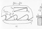
In fig. V-7 shows a simplified diagram of the automation of the autoclave processing of reinforced concrete products. The scheme is based on the automatic system of typical regulation of autoclaves "Astra" with some changes. In the initial period, regulation is carried out by temperature, and when a certain temperature is reached, it switches to pressure regulation. This makes it possible to avoid a number of disadvantages that arise when regulating according to any one parameter of the autoclave process.
The scheme works as follows. After loading the autoclave and tightly closing the lids from the steam protection circuit of the autoclave (CPZ), a signal is sent to the command electro-pneumatic device KEP-12u and the steaming process begins. The temperature rise program is set by the 1zh programmer of the PD-44UM type. Resistance thermometer 1a, type TSP, which measures the temperature in the autoclave, through a normalizing converter of type NP-SL-1 and indicating device 1b of type N342K sends a unified converted signal of 0-5 mA to a regulating device 1e of type ZRP2S. The programmer generates an electrical signal of direct current 0-5 ma, changing in time according to a given program.
When the current temperature value mismatches with the set one, the regulating device amplifies the mismatch signal and, depending on the sign of this signal, acts on the electromagnets EV1 and EV2 and the membrane actuators Ml and M2 for steam inlet and outlet, maintaining the temperature in the autoclave within the set limits.

Rice. V-7. Autoclave processing automation scheme (mnemonic shield and general measurement shield are conventionally not shown)
With a lack of coolant, electrical signals can be used to proportionally increase the duration of the steaming mode. When a certain temperature is reached, at which the signal from the normalizing temperature transducer becomes equal to the signal from the pressure transducer using the positional control device 1b installed on the H342K device, it switches to pressure control. A relay is switched on from the contact of the positioning device, which disconnects the normalizing temperature transducer from the regulating device and connects to it a pressure sensor 1g of the MTM type with a self-recording device 1d of the H340 type.
Subsequently, the heat treatment process is controlled by pressure.
Category: - Machines in the production of building materialsThe industrial autoclave RV-0.1.1.0.E.0.0.0 is intended for impregnation of cast parts in order to seal them.
DEVICE AND OPERATING PRINCIPLE OF THE INDUSTRIAL AUTOCLAVE.
The autoclave is a single-walled sealed container mounted on a stretcher.
The autoclave has a hinged lid, which is fastened with hinged bolts. The design of the autoclave provides for a system of pipelines and valves, which makes it possible to measure the technological parameters of the product processing in a wide range.
The industrial autoclave operates according to the following technological cycle:
Place the parts in the autoclave, close the lid;
- create a vacuum in the autoclave;
- open the valve for supplying the impregnating compound, close the valve;
- create a vacuum in the autoclave;
holding time in accordance with the technological process;
- release the vacuum;
- create overpressure in the autoclave,
holding time in accordance with the technological process;
- relieve pressure;
- open the tap to remove the impregnating compound, close the tap;
- open the lid, remove the parts from the autoclave, immerse in a bath of cold water.
We develop and manufacture industrial autoclaves according to the customer's specifications
of any volume, configuration, for various industries.
The plant has a Permit from ROSTEKHNADZOR for the right to use steel welded tanks, vessels and apparatuses with a capacity of up to 200 m2 at hazardous production facilities related to the handling of explosive and fire hazardous and chemically hazardous substances.
Similar equipment:
 |
 |
|
 |
 |
 |
Household autoclave NEFOR 16 made of stainless steel is a device for preserving food in glass jars at home without the use of preservatives.
Preservation allows you to cook meat, fish, mushrooms, vegetables, compotes, juice, pates in natural juice without preservatives. Autoclave-sterilizer NEFOR is suitable for canning vegetables in the form of caviar, salads, lecho. With the autoclave, you will have a varied and healthy menu all year round.
Advantages of the NEFOR 16 autoclave
At a conservation temperature of 120 ° C and above, all harmful microorganisms are destroyed. That's why food becomes safe and the shelf life of products increases: they can be stored for up to 2 years or more.
Correct preservation preserves amino acids, vitamins and other organic substances in food, which are necessary for healthy metabolism and energy balance.
Autoclave NEFOR 16 for home canning is made of quality stainless steel. This means that there will be no dirty stains from rust inside the tank. In addition, the steel is made to a special standard for food preparation.
Capacity: the autoclave contains 16 cans of 0.5 or 0.65 l or 5 cans of 1 l. You can combine cans and other sizes as you wish.
Without parts for electrical operation, the NEFOR autoclave is independent of the power supply and easy to use.
Reliability: Every NEFOR autoclave is thoroughly tested.
First of all, it is checked for tightness. It is completely assembled into working condition and the pressure is brought to 6 atmospheres. The autoclave is left in this state for 12 hours. Only devices that have passed the test are sent for sale.
Includes a removable, adjustable stand for convenient use on electric stoves.
Saving: autoclaves with an external heating principle are cheaper than electric counterparts with an internal heater.
Sterilization in a NEFOR autoclave allows
- reliably destroy bacteria present in canned food;
- reduce the time of heat treatment, which improves the quality of canned products;
- increase the shelf life of products;
- exclude the use of preservatives;
- do not pre-sterilize the jars and do not boil the lids.
Enjoy your cooking!
| Main characteristics | |
|---|---|
| Type of | |
| Heater | external |
| Capacity, l | 16 |
| Material | stainless steel |
| Dimensions (edit) | |
| Dimensions, mm | 300x400x600 |
| Weight, kg | 11 |
| Spaciousness | |
| 8 | |
| 8 | |
| Total cans of 0.5 l, pcs | 16 |
| Total cans 1 l, pcs | 5 |
| Performance indicators | |
|---|---|
| 122 | |
| 0,15 | |
| Autoclave complete set | |
| safety valve | there is |
| Pressure gauge | there is |
| Thermometer | there is |
| Warranty information | |
| Country | Russia |
| Manufacturer | SP Nesterova |
| Warranty, month | 12 |
| Service life, years | 5 |
The manufacturer reserves the right to change the characteristics of the product, its appearance and completeness without prior notice to the seller.
Information that is absent in the specified characteristics of the goods, provided for in Article 10 of the Law of the Russian Federation "On Protection of Consumer Rights" and paragraph 8 of the "Rules for the sale of goods by remote means" (including location, manufacturer's name; service life; information on mandatory confirmation of compliance with established requirements) , is provided (in accordance with clause 2 of the "Rules for the sale of goods by remote means") by phone or e-mail by the managers of the company, by the courier at the time of delivery before the transfer of the goods to the client.
Features Autoclave NEFOR 16, stainless steel, thermomanometer, safety valve, removable handles
| Main characteristics | |
|---|---|
| Type of | for gas and electric stoves |
| Heater | external |
| Capacity, l | 16 |
| Material | stainless steel |
| Dimensions (edit) | |
| Dimensions, mm | 300x400x600 |
| Weight, kg | 11 |
| Spaciousness | |
| Number of cans in 1 layer, 0.5 l, pcs | 8 |
| Number of cans in 2 layer, 0.5 l, pcs | 8 |
| Total cans of 0.5 l, pcs | 16 |
| Total cans 1 l, pcs | 5 |
| Performance indicators | |
|---|---|
| Max. t ° in sterilization mode, ° C | 122 |
| Max. pressure in sterilization mode, MPa (kgf / cm2) | 0,15 |
| Autoclave complete set | |
| safety valve | there is |
| Pressure gauge | there is |
| Thermometer | there is |
| Warranty information | |
| Country | Russia |
| Manufacturer | SP Nesterova |
| Warranty, month | 12 |
| Service life, years | 5 |