A simple problem arose. I needed a manually adjustable PWM to test one idea. Tinka 13 is at hand - i.e. we hook the variable to the ADC and output what we need. It would seem - it's easier just to blink the LED. But. It was getting dark.
Everything is quickly plugged into the layout, with the help of the wizard in CodeVision, the project is assembled with a few clicks. For output test - LED. I turn it on: it burns to the full, I twist the resistor - there is no reaction. I quickly check all the connections, power, circuitry, firmware - the effect remains. After repeating the same actions three times, bewilderment arose. I take another tinka, flash it, turn it on - a bolt. It looks like the chip is not the problem. I have been contemplating the code generated by CodeVision for some time - there is nothing to complain about. I open the datasheet, I delve into it. I studied ADC, checked it - everything is according to the canons. Moved to PWM.
Brief description of the Attiny13 hardware PWM device for beginners:
PWM is based on a timer. Those. the timer has several modes of operation, two of them are related to PWM (FastPWM and Phase Correct PWM). The timer is configured using two registers: TCCR0A, TCCR0B. They set the mode, frequency (divider), which channels are used (there are two - 0A and 0B), the output operation mode (direct, inverted). The PWM value is set in the OCR0A and OCR0B registers - respectively for each channel. PWM also has such a setting - what determines the maximum value of the timer (TOP), upon reaching which it is reset and runs from the beginning - it can be either 0xFF or the value in the OCR0A register. I had the second mode set and I set the PWM value in the OCR0A register.
It took me a lot of time until I found my mistake and even more until I caught up with its meaning. Although now everything seems obvious. For those who, like me, are in the tank - TOP should be 0xFF. It should be noted that setting modes through registers does not please with an intuitive interface. So the above mode is determined by the WGM02:0 bits, two of which are in the TCCR0A(00,01) register, and the third (02) in TCCR0B. True, the CodeVision master at the initial setup is our everything, but when you need to correct something already in the process, this is where you have to work hard.
In short, the following rake. The brightness is adjustable, but here's the problem: when I bring the knob to a minimum, it still highlights. Those. we have 0 on the ADC, but the output is not 0. It's a shame, you understand. The reason for this behavior is that at the moment when the timer is reset to 0, the chip sets 1 at the output, and although the PWM value is set to 0, and in the next cycle it sees this and resets the output, but this unfortunate jump is enough so that the LED lights up. Discomfort - you are waiting for a clean 0 at the exit, and here you have such a comb. Generally speaking, the problem is known. The solution comes to mind almost immediately: when we change the PWM value, add a check to 0 - with it, we turn off the PWM completely. The question arises: how to turn it off? You can stop the timer. Not the best way: what if something else is planted on this timer? A second PWM, for example, or interrupts, or a countdown to an explosion? You can turn off the timer output - this is already better, and simple and clear, it turns out something like this:
if(OCR0A==0)TCCR0A&=0x3F; else TCCR0A=0x83;
Alternatively, you can change the operating mode of the output / input pin itself.
P.S.
The following solutions were obtained from the comments to the article:
1. If it is not important to get 100% PWM filling, then you can use the inverse mode of the output;
2. When PWM is running in Phase Correct PWM mode, there is no problem.
Sometimes in the amateur radio business, a variable duty cycle (SC) oscillator is needed to check various schemes, power output stages of SMPS, etc. And also to check the PWM chip itself.
The generator is assembled on a common Unitrode UC3843 PWM or similar.
To increase the power supply reliability, the input is integral stabilizer LM7812, since the current consumed directly by the generator itself (without load) does not exceed 25..30mA, I used a stabilizer in TO92 performance.
Diode D1 protection from a fool (or just inattention).
Resistor R5 limits the output current, protecting the chip in case of short circuit exit. Resistor R1 limits the maximum frequency and is timing together with the capacitor C1. Capacitors C4, C5 shunt the power supply of the stabilizer, C3 PWM power, and the capacitor C2 filters the output voltage of the reference voltage source, which, with a working microcircuit, should be about 5 volts.
Next, the variables:
RV1(50 kOhm) - is part of the timing RC chain and, accordingly, regulates the frequency of the generator, in the upper position the frequency is minimal.
RV2(5 kOhm) - regulates the duty cycle of the generator (short circuit, duty cycle).
RV3(1 kOhm) - allows you to fine-tune the operating point of the circuit feedback in order for the regulator RV2 allowed to adjust the short circuit from a minimum to a maximum.
The design does not need to be adjusted, and with serviceable parts and proper installation, it starts working immediately. Bourgeois 2N2222 can be replaced with our KT3102 or any similar one. Capacitors C2, C3, C4 and C5 are not necessary for the operation of the circuit, as well as R5.
With the ratings indicated in the diagram, the generator frequency is regulated from approximately 16.9 kHz to 250 kHz, closer to the maximum frequency, the fronts are slightly gentle and are about 0.2 μs, the maximum duty cycle is limited to approximately 90%
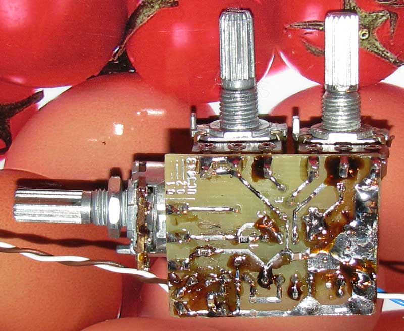
The circuit is operable in the range from 12 to 30V, if you remove the stabilizer, then the lower limit will expand to 9V, but then it will be dangerous to power the structure with a voltage above 20V: as practice has shown, at 30V the UC3843 shatters into pieces, trying to get into the eyes or face. I made the design on a one-sided fiberglass 1.5mm thick using LUT, the board dimensions are 30x37mm, there are no jumpers.
After desoldering the components and flushing from the flux, I recommend covering the side with the tracks with zaponlak.
I used both smd and classical components, those who wish can change the wiring as they see fit.
The microcircuit is inserted into the DIP8 socket, which allows you to check the microcircuits without soldering anything. The board in lay format for Sprint Layout can be downloaded from this.
This is how it looks like:

Generation PWM at STM32 It is carried out using timers, a lot is written about them in the documentation, but it turned out to be quite easy to set up PWM. To generate PWM we will be using 4th channel first timer.
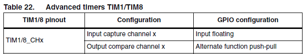
The first step is to find which output is responsible for the 4th channel of the first timer, for this we open Technical DataSheet to your MK, I have STM32F103VET6, and find the alternative function of which output is TIM1_CH4.
To use the timer, the output must be configured as push-pull.
Let's look at the registers we'll need.
TIMx_PSC is the input frequency prescaler, its value can be calculated by the formula
F = fCK_PSC / (PSC + 1)
- F- the frequency with which the timer is clocked
- fCK_PSC- timer frequency to divider
- PSC- PSC register value
TIMx_CCRy[x– timer number, y– channel number] – defines the PWM duty cycle. That is, if in ARR we will write 1000, and in CCRy 300, then the duty cycle at a positive active level and direct PWM will be equal to 0.3 or 30%.
TIMx_CNT– counting 16-bit register, changes its value by ±1 with the arrival of each pulse, depending on the direction of counting.
TIMx_CR1 ->DIR– counting direction register, when set to "0" the counter counts up, when set to "1" - down. When the counter is configured in center alignment mode, the bit is read-only.
TIMx_CCER->CCyE[x– timer number, y– channel number] – setting this bit to "1" allows using the corresponding timer channel as an output, including for PWM generation.
TIMx_BDTR->MOE– Setting this bit to one enables the timer pins to be used as outputs.
bits OCyM, where y- channel number, in register TIMx_CCMR allow you to select the PWM mode, direct or inverse.

I must say that the first and second channels are configured in the register CCMR1, and the third and fourth in the register CCMR2.
TIMx_CCER->CCyP[x- timer number, y- channel number] - this bit allows you to choose what the active level will be, "0" - high, "1" - low.
TIMx_CR1 ->CMS- allows you to select the alignment mode on the front or in the center, which is similar to Fast PWM and Phase Correct PWM at AVR.
- 00: Edge alignment mode. The counter counts up or down depending on the direction bit (DIR).
- 01: Center alignment mode 1. The counter counts up and down. Interrupt flags are set from output configured channels (CCxS=00 in TIMx_CCMRx) only when the counter is counting down.
- 10: Mode 2 center alignment. The counter counts up and down. Interrupt flags are set from output configured channels (CCxS=00 in TIMx_CCMRx) only when the counter is counting up.
- 11: Mode 3 center alignment. The counter counts up and down. Interrupt flags are set from channels set to output (CCxS=00 in TIMx_CCMRx) when the counter is counting up and down.
Let's write the code to generate PWM with front alignment.
#include "stm32f10x.h" int main (void) ( // Clocking GPIOA , TIM1, port aliases RCC->APB2ENR |= RCC_APB2ENR_IOPAEN | RCC_APB2ENR_TIM1EN | RCC_APB2ENR_AFIOEN; //PA11 push-pull GPIOA->CRH &= ~GPIO_CRH_CNF11; GPIOA->CRH |= GPIO_CRH_CNF11_1; GPIOA->CRH &= ~GPIO_CRH_MODE11; GPIOA->CRH |= GPIO_CRH_MODE11_1; GPIOA->CRH |= GPIO_CRH_MODE11_1; // TIM1 divisor->PSC = 72; // TIM1 reset value-> ARR = 1000; //duty factor TIM1->CCR4 = 300; //set channel 4 output, active level low TIM1->CCER |= TIM_CCER_CC4E | TIM_CCER_CC4P; //allow timer pins to be used as outputs TIM1->BDTR | = TIM_BDTR_MOE; //PWM mode 1, direct PWM channel 4 TIM1->CCMR2 = TIM_CCMR2_OC4M_2 | TIM_CCMR2_OC4M_1; //if you need to configure the first channel, you can do this //TIM1->CCMR1 = TIM_CCMR1_OC1M_2 | TIM_CCMR1_OC1M_1; //count up TIM1 ->CR1 &= ~TIM_CR1_DIR; // edge alignment, Fast PWM TIM1->CR1 &= ~TIM_CR1_CMS; // enable counter TIM1->CR1 |= TI M_CR1_CEN; )
Let's see what happened.
In some cases, such as in flashlights or household lighting fixtures, there is a need to adjust the brightness of the glow. It would seem that it’s easier: just change the current through the LED by increasing or decreasing. But in this case, a significant part of the energy will be consumed on the limiting resistor, which is completely unacceptable for autonomous power supply from batteries or accumulators.
In addition, the color of the LEDs will change: for example, White color when the current drops below the nominal value (for most LEDs 20mA) it will have a slightly greenish tint. Such a change in color in some cases is completely useless. Imagine that these LEDs illuminate the screen of a TV or computer monitor.
In these cases, apply PWM - regulation (width - pulse). Its meaning is that it periodically lights up and goes out. In this case, the current remains nominal throughout the entire flash time, so the luminescence spectrum is not distorted. If the LED is white, then green shades will not appear.
In addition, with this method of power control, energy losses are minimal, the efficiency of circuits with PWM control is very high, reaching more than 90 percent.
The principle of PWM - regulation is quite simple, and is shown in Figure 1. A different ratio of the time of the lit and extinguished state is perceived by the eye as a different brightness of the glow: like in a movie - separately shown frames in turn are perceived as a moving image. It all depends on the projection frequency, which will be discussed a little later.

Figure 1. The principle of PWM - regulation
The figure shows the signal diagrams at the output of the PWM control device (or master oscillator). Zero and one are indicated: a logical one (high level) causes the LED to glow, a logical zero (low level), respectively, extinction.
Although everything can be the other way around, since it all depends on the circuitry of the output key, turning on the LED can be done at a low level and turning it off, just high. In this case, a physically logical one will have a low voltage level, and a logical zero will be high.
In other words, a logical one causes some event or process to turn on (in our case, the LED lights up), and a logical zero should turn off this process. That is, the output level is not always high. digital microcircuit is a LOGICAL unit, it all depends on how a particular circuit is built. This is so, for information. But for now, we will assume that the key is controlled by a high level, and it simply cannot be otherwise.
Frequency and width of control pulses
Note that the pulse period (or frequency) remains unchanged. But, in general, the pulse frequency does not affect the brightness of the glow, therefore, there are no special requirements for frequency stability. Only the duration (WIDTH), in this case, of a positive pulse changes, due to which the whole mechanism of pulse-width modulation works.
The duration of the control pulses in Figure 1 is expressed in %%. This is the so-called "duty cycle" or, in English terminology, DUTY CYCLE. It is expressed as the ratio of the duration of the control pulse to the pulse repetition period.
In Russian terminology, it is usually used "duty cycle" - the ratio of the repetition period to the time of the impulse a. Thus, if the fill factor is 50%, then the duty cycle will be equal to 2. There is no fundamental difference here, therefore, you can use any of these values, to whom it is more convenient and understandable.
Here, of course, one could give formulas for calculating the duty cycle and DUTY CYCLE, but in order not to complicate the presentation, we will do without formulas. Last but not least, Ohm's law. There's nothing you can do about it: "You don't know Ohm's law, stay at home!" If anyone is interested in these formulas, they can always be found on the Internet.
PWM frequency for dimmer
As mentioned a little higher, there are no special requirements for the stability of the PWM pulse frequency: well, it “floats” a little, and that’s okay. PWM controllers have a similar frequency instability, by the way, quite large, which does not interfere with their use in many designs. In this case, it is only important that this frequency does not fall below a certain value.
And what should be the frequency, and how unstable can it be? Do not forget that we are talking about dimmers. In film technology, there is a term "critical flicker frequency". This is the frequency at which individual pictures displayed one after the other are perceived as a moving picture. For the human eye, this frequency is 48 Hz.
This is precisely the reason why the frame rate on film was 24fps (the television standard is 25fps). To increase this frequency to the critical one, film projectors use a two-bladed obturator (shutter) that overlaps each displayed frame twice.
In amateur narrow-film 8mm projectors, the projection frequency was 16 frames / sec, so the obturator had as many as three blades. The same purpose in television is served by the fact that the image is shown in half-frames: first even, and then odd lines of the image. The result is a flicker frequency of 50 Hz.
The operation of the LED in PWM mode is a separate flash of adjustable duration. In order for these flashes to be perceived by the eye as a continuous glow, their frequency must in no way be less than the critical one. Any higher, but no lower. This factor should be taken into account when creating PWM - controllers for lamps.
By the way, just like interesting fact: scientists have somehow determined that the critical frequency for the eye of a bee is 800Hz. Therefore, the bee will see the movie on the screen as a sequence of separate images. In order for her to see a moving image, the projection frequency will need to be increased to eight hundred fields per second!
To control the actual LED is used. V Lately most widely used for this purpose are MOSFET transistors, which allow switching significant power (the use of conventional bipolar transistors considered simply indecent).
Such a need, (powerful MOSFET - transistor) arises when in large numbers LEDs, for example, at , which will be discussed a little later. If the power is low - when using one or two LEDs, you can use low-power switches, and if possible, connect the LEDs directly to the outputs of the microcircuits.
Figure 2 shows a functional diagram of a PWM controller. Resistor R2 is conditionally shown as a control element in the diagram. By rotating its knob, you can change the duty cycle of the control pulses within the required limits, and, consequently, the brightness of the LEDs.
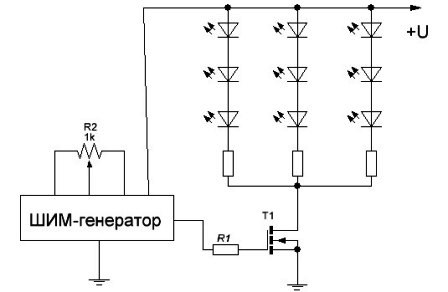
Figure 2. Functional diagram PWM controller
The figure shows three strings of LEDs connected in series with terminating resistors. Approximately the same connection is used in LED strips. The longer the tape, the more LEDs, the greater the current consumption.
It is in these cases that powerful ones will be required, the allowable drain current of which should be slightly more than the current consumed by the tape. The last requirement is met quite easily: for example, the IRL2505 transistor has a drain current of about 100A, a drain voltage of 55V, while its size and price are quite attractive for use in various designs.
PWM master oscillators
A microcontroller can be used as a master PWM oscillator (most often in industrial conditions), or a circuit made on microcircuits with a low degree of integration. If it is planned to make a small number of PWM controllers at home, and there is no experience in creating microcontroller devices, then it is better to make a controller on what is currently at hand.
These can be logic circuits of the K561 series, integrated timer, as well as specialized circuits designed for. In this role, you can even make it work by collecting on it adjustable generator, but this is, perhaps, "for the love of art." Therefore, only two schemes will be considered below: the most common on the 555 timer, and on the UC3843 UPS controller.
Schematic of the master oscillator on the timer 555
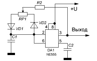
Figure 3. Schematic of the master oscillator
This circuit is a conventional generator rectangular pulses, the frequency of which is set by the capacitor C1. The capacitor is charged through the circuit "Output - R2 - RP1-C1 - common wire". In this case, there should be a voltage at the output high level, which means that the output is connected to the positive pole of the power source.
The capacitor is discharged along the circuit "C1 - VD2 - R2 - Output - common wire" at a time when a low-level voltage is present at the output - the output is connected to a common wire. It is this difference in the charge-discharge paths of the time-setting capacitor that provides pulses with adjustable width.
It should be noted that diodes, even of the same type, have different parameters. In this case, their electrical capacitance plays a role, which changes under the action of voltage across the diodes. Therefore, along with the change in the duty cycle of the output signal, its frequency also changes.
The main thing is that it does not become less than the critical frequency, which was mentioned a little higher. Otherwise, instead of a uniform glow with different brightness, individual flashes will be visible.
Approximately (again, the diodes are to blame), the frequency of the generator can be determined by the formula shown below.
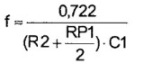
The frequency of the PWM generator on the timer 555.
If we substitute the capacitance of the capacitor in farads, the resistance in Ohms, then the result should be in hertz Hz: you can’t get away from the SI system! This assumes that the engine variable resistor RP1 is in the middle position (in the formula RP1/2), which corresponds to the square wave output signal. In Figure 2, this is exactly the part where the pulse duration is 50%, which is equivalent to a signal with a duty cycle of 2.
PWM master oscillator on a UC3843 chip
Its scheme is shown in Figure 4.
![]()
Figure 4. Schematic of the PWM master oscillator on the UC3843 chip
The UC3843 chip is a control PWM controller for switching power supplies and is used, for example, in ATX format computer sources. In this case typical scheme its inclusion is slightly changed towards simplification. To control the width of the output pulse, a control voltage of positive polarity is applied to the input of the circuit, then the output is pulse signal PWM.
In the simplest case, the control voltage can be applied using a variable resistor with a resistance of 22 ... 100 KΩ. If necessary, the control voltage can be obtained, for example, with analog sensor illumination, made on a photoresistor: the darker it is outside the window, the brighter it is in the room.
The regulating voltage acts on the PWM output in such a way that when it is reduced, the output pulse width increases, which is not at all surprising. After all, the original purpose of the UC3843 chip is to stabilize the voltage of the power supply: if the output voltage drops, and with it the regulating voltage, then measures must be taken (increase the width of the output pulse) to slightly increase the output voltage.
Regulating voltage in power supplies is generated, as a rule, using zener diodes. More often than not, this or something similar.
With the ratings of the parts indicated on the diagram, the generator frequency is about 1 kHz, and unlike the generator on the 555 timer, it does not “float” when the duty cycle of the output signal changes - taking care of the frequency of switching power supplies.
To regulate significant power, for example, LED Strip Light, a key stage on a MOSFET transistor should be connected to the output, as shown in Figure 2.
It would be possible to talk more about PWM controllers, but for now let's stop there, and in the next article we will consider various ways connecting LEDs. After all, not all methods are equally good, there are those that should be avoided, and there are simply plenty of errors when connecting LEDs.
The shopping cart allows you to create a list of items for placing an order. You can fill the basket using any of the 7 search options for items:
- capable of recognizing more than 3 million items
- – a catalog containing hundreds of thousands of products
- passive components by main parameters
- Publications such as:, and; containing specific names of electronic components
- , with a list of what was ordered earlier
- Personal, in which you can store the lists of elements you need
- , with which you can very quickly load and recognize a large list of elements
The shopping cart allows you to select warehouse offers for each item, if this has not been done in advance. For ease of use, added the ability to postpone the selected items of the shopping cart for the next time.
It does not matter in which program you store a list of regularly purchased items. You can copy a list from any program that allows you to select and copy the contents of a table, for example from Microsoft programs Excel, 1C, etc..
Additional functions "Auto search" and "Manual recognition" will help to adapt the desired names of electronic components to 100% compliance with the Compel's nomenclature base, including taking into account stock availability.
Often, resistors and capacitors are contained in the list of items for purchase not in the form of specific items, but in the form of a set of required parameters, for example “Resistor 4.7 kOhm 5% 0805″ or “Capacitor 0.1 uF 50V X7R 0805″. New tool"Express search by parameters" allows you to quickly search for an electronic component by the most basic technical parameters.
The new tool will make the purchase of components much easier, more convenient and faster. For example, to search for the required resistor by the main parameters (resistance, case, power and tolerance), it will take only 9 mouse clicks and a few seconds of your attention.
List of all used product names.
The tool is designed for long-term storage of lists of items, lists of regular requirements, frequently used items and any other item lists. Each list can be given a name and short description. For each position, operational information on availability and cost is available. The nomenclature inside the lists can be freely copied, moved, deleted. By selecting several items at the same time, you can quickly make a purchase - send items to the basket.
Page under availability control
It is not uncommon for the name of the same physical product to be spelled differently by different suppliers and buyers. In addition, the names of some product groups, especially for passive components, are often stored in the buyer's database not as a specific order code of a specific manufacturer, but as a short set of basic parameters. The purchase of goods due to such ambiguity can take a very long time each time, since the requested items must be accurately identified according to the seller's nomenclature guide. The ”correspondence table” tool allows you to store and manage the correspondence of items from the buyer's database to the Compel's stock list database. You can fill in this table both line by line manually, and in the “training mode” when importing the list. These matches will be used for reliable name recognition on subsequent list downloads.
The section contains a history of all requests sent through the site over the past 12 months. The contents of sent requests can be partially or completely copied to the basket and a new order can be easily created.
The section allows you to specify the personal and legal data necessary for full-fledged work on the site. Add to your account entity, whose representative you are, and all the commercial functions of the site will open for you. Set up subscription options to receive only what you are personally interested in in your mail. At any time, securely change your password to access the site.
Our in-house engineering support team can help you select the right electronic component for your needs. electrical parameters or, if necessary, find a replacement for an item that is out of stock.
User guide
To activate the functionality, please log in.