At the time of the hobby for tourism, a Duracell lantern was purchased with a powerful krypton lamp on two large D-size batteries (in the Soviet version, type 373). The light was excellent, but it took 3-4 hours to drain the batteries.
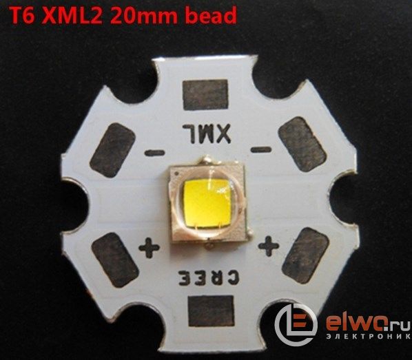
In addition, there was a nuisance twice - the batteries leaked and electrolyte flooded everything inside the flashlight. The contacts oxidized, covered with rust, and even after cleaning and installing new batteries, the flashlight no longer inspired confidence, and even more so the batteries. It was a pity to throw it away, and not to be able to use it, prompted the idea to remake the flashlight for the now fashionable lithium battery and LED. For half a year, there was a Sanyo 18650 lithium battery with a capacity of 2600 mA / h in the bins, and I wrote out such an LED from my Chinese comrades (allegedly Cree XML T6 U2) with an operating voltage of 3-3.6 V, a current of 0.3-3 A (again, allegedly - with a power of 10 W), a luminous flux of 1000-1155 lumens, a color temperature of 5500-6500 K and a dispersion angle of 170 degrees.
Since the experience of converting flashlights to power from lithium batteries was already (and), I decided to go the same way: to use a well-proven bundle: 18650 battery and TP4056 charge controller. One problem remained to be solved - which driver to use for the LED? You can't get off with a simple current-limiting resistor - the power of the LED, even if not 10 watts, as the Chinese comrades say, but still. Studying the material on "driver construction for high-power LEDs" I came across a very interesting, and as it turned out, often used AMC7135 microcircuit. On the basis of this microcircuit, the Chinese have long and successfully flooded the planet with their lanterns). Schematic diagram of the power supply of a powerful LED based on AMC7135.
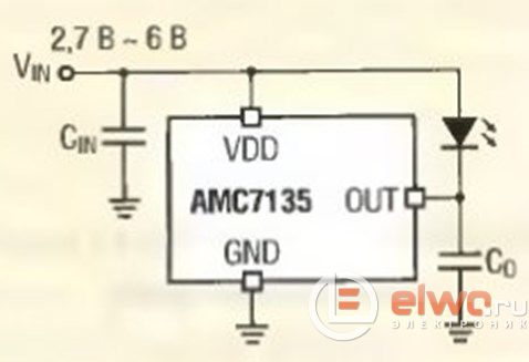
As you can see, power supply in the range of 2.7 ... 6 V is allowed, and this is a fairly wide range of power sources, including lithium batteries. The chip's job is to limit the current flowing through the LED to 350mA.
According to the chip manufacturer, the capacitor Co should be used if:
- the length of the conductor between the AMC7135 and the LED is more than 3 cm;
- the length of the conductor between the LED and the power supply is more than 10 cm;
- LED and IC are not installed on the same board.
In reality, flashlight manufacturers often neglect these conditions and exclude capacitors from the circuit. But as the experiment showed, it was in vain, about which a little later. Additional advantages of the AMC7135 type IC include the presence of built-in protection in case of open circuit, short-circuit of the LED and the operating temperature range of -4O ... 85 ° C. Detailed documentation for the AMC7135 chip is available.
Electric lantern circuit
Another important and extremely useful feature of this microcircuit is that they can be installed in parallel to increase the current flowing through the LED. As a result, the following scheme was born:
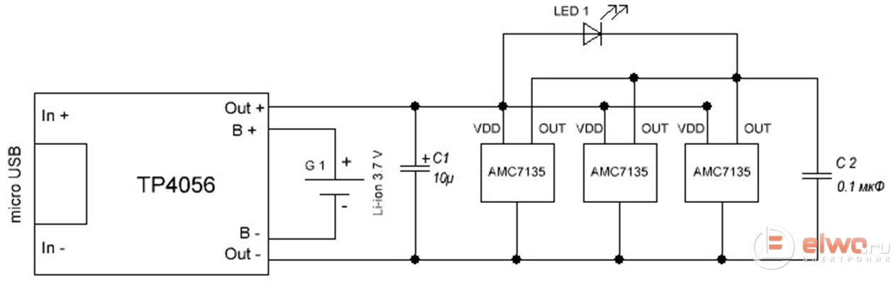
Based on it, the current flowing through the LED will be 1050 mA, which, in my opinion, is more than enough for a not tactical, but an economic flashlight. Then I started assembling everything into a single system. Using a dremel in the lamp housing, I removed the battery guides and contact rails:
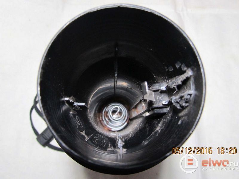
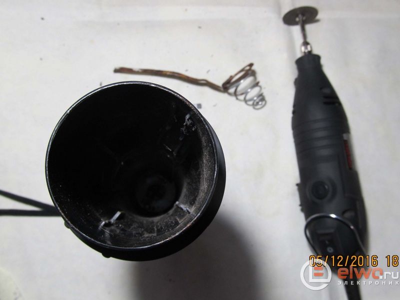
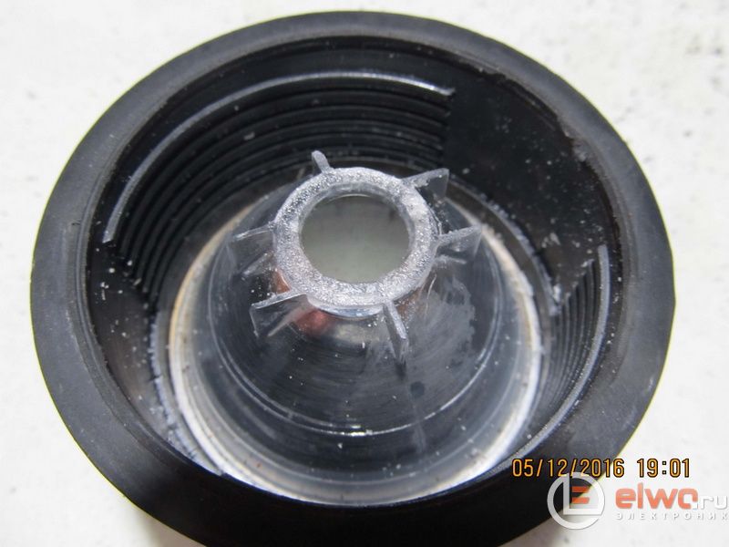
Dremel also removed the landing socket for the krypton lamp and formed a platform for the LED
Since a powerful LED emits a lot of heat during operation, I decided to use a heat sink removed from the motherboard to dissipate it.
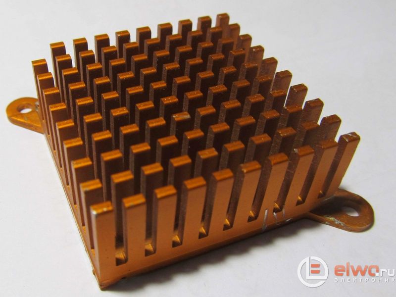
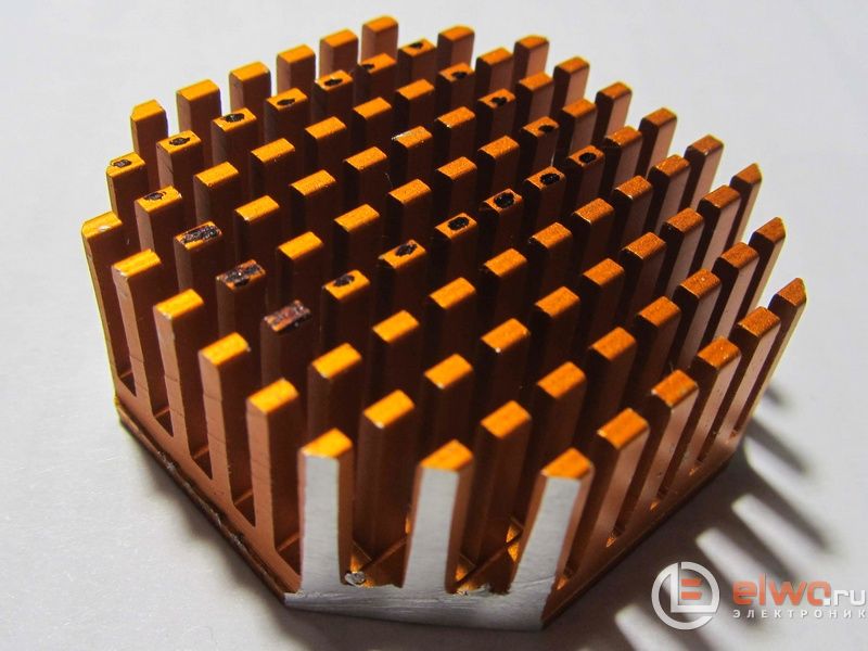
According to the idea, the LED, the heat sink and the head part of the flashlight with the reflector will form one whole and, being screwed onto the body of the flashlight, should not cling to anything. To do this, I cut off the edges of the heat sink, drilled holes for the wires and glued the LED to the heat sink with hot glue.


