Sadly, you have to start with theory. We'll have to study the types of diodes, the scope and purpose of the application. Without delving into the physical foundations of electronics, let's go over the search queries. It is important to understand that all diodes are united by the ability to pass current in one direction, blocking the movement of particles in the opposite direction, forming a kind of valves. Then we will discuss how to test a diode with a multimeter.
Varieties of diodes
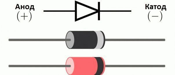
So, diodes pass current in the forward direction and block in the opposite direction. In electrical diagrams, diodes are indicated by black arrows bounded by a cross line. The symbol shows the direction of the current in the physical sense - the directed movement of positive particles. To create a direct current, a negative potential is applied to the end of the arrow, and a positive potential to the beginning. Otherwise, the diode will be in a "locked" state.
When electrons move due to the imperfection of the molecular lattice, heat is lost, which entails a voltage drop in the forward direction. For silicon diodes, the forward potential is higher, for germanium diodes, it is lower. Schottky diodes are characterized by a smaller potential drop due to the replacement of one semiconductor layer with a metal one, i.e. it has no pn junction. The loss current is increasing and the forward voltage drop across the open switch is at an all-time low.
The effect is not characteristic for all voltage ranges. Schottky diodes are most effective at voltages equal to tens of volts. They are used in the output filters of switching power supplies. Remember: the voltage ratings of the system unit are 5, 12, 3 V. The method of constructing circuits on a Schottky diode is typical.
A popular type of diode is a zener diode. Its working area is the breakdown area. Where a conventional diode fails, the Zener diode protects the equipment. The process is characterized by an increase in voltage to the nominal value and a sharp stabilization. Through zener diodes, sensitive and weak microcircuits of controllers of switching power supplies are fed from high-voltage lines, so that they cut the voltage with pulses of large amplitude. Without zener diodes, powering the microcircuits is solved by daunting methods.
When evaluating a zener diode using a multimeter, it is taken into account that the working area is the reverse branch. Technically, the breakdown voltage for testing is obtained from batteries connected in series, then stabilization is checked. Direct switching on of the zener diode is used extremely rarely, ringing in the traditional way is a bad idea. An avalanche diode is also referred to as zener diodes, where the effect of impact ionization is applied to stabilize the current.
It happens that the specifics of the device are not clear. The printed circuit boards are marked - each element has a strictly defined designation, and the powerful diodes of the rectifier bridge cannot be confused with a tiny glass zener diode. The worst option is a tangle of conductors with incomprehensible elements: either a diode, or an unusual-looking resistor, or an exotic capacitor.
Faced with a similar situation, they carefully take an enlarged photo, then search on the Internet for the image. Although the zener diode markings are illegible, it is possible to find information on the network. This step greatly speeds up the process of identifying and assessing the performance of the device.
The infrared diode is checked with a multimeter in the same way: we remove the forward voltage, then make sure that the current does not flow back. To check the glow, use the viewfinder of a night video camera. It detects directly the infrared radiation of objects. A working IR diode is visible on the viewfinder like an asterisk. They check the glow with thermal imagers, night vision devices, being careful: the radiation power of light and IR diodes is high, comparable to the power of laser radiation.
The inscription inside the printer about the presence of a laser is not a joke. And neglect it. Keep the retina away from the infrared diode.
How to check a diode using a tester
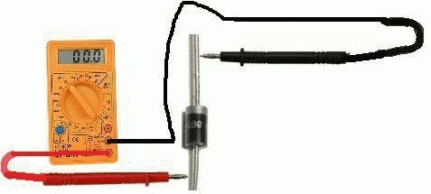
To test diodes, multimeters are equipped with a special scale marked with a corresponding icon - a schematic diode designation. When the mode is turned on, low resistances turn on the buzzer, high resistances are characterized by a nominal value or a voltage drop across it. According to the readings, they judge the characteristics of the diode, for example, the resistance of the direct connection.
For the correct interpretation of the readings, it is important to take into account the characteristics of the tester: voltage of a constant kind and a low nominal value used for evaluation. Example: when measuring resistance, the tester passes a current through it, applying a certain voltage to the probes. Any multimeter model has unique parameters. The voltage is recognized by the charge of the capacitor: it turns on the multimeter in the dialing mode or diode testing, after a short time a potential difference will form on the capacitor plates. Measured with the standard tester scale. The value ranges from hundreds of millivolts (fractions of a volt) to units of volts.
Knowing the voltage applied to the diode, the reliability of the reading is verified by its current-voltage characteristic. They enter a search query on Yandex, get acquainted with the full technical documentation for the element under study. Then a ruler is applied in the right place on the abscissa scale to find the output current. Using Ohm's formula, the on-state resistance is calculated: R = U / I, where U is the auxiliary voltage generated by the tester. The value found according to the graph is compared with that indicated on the scoreboard.
This is one of the many techniques. It is important to know how to find the right paths, analyze and compare data. The first step is to search for generalized information: what diodes are, their characteristics (first of all, volt-ampere), the subtleties of the operation of a particular device. Knowing the theoretical foundations, it is easy to operate with information, draw correct conclusions from research results.
Let's move on to a real life example: examining a diode bridge from a car generator!
How to determine the performance of a diode bridge
The car needs electricity - for air conditioning systems (along with engine energy), wipers, interior and exterior lighting. It is not economical to load the battery all the time, which is done while stationary. The problem is solved by connecting a synchronous alternator to the motor shaft. Previously, they used a collector circuit. But the brushes do not tolerate shaking, there was a need for frequent maintenance.
Nowadays, three-phase generators are installed. Because the revolutions are constantly jumping, the constancy of the output characteristics is maintained by changing the rotor feed current. As a result, the stator's alternating magnetic field tracks every change in motor operation. The payback is the instability of the output voltage. It is rectified and filtered using the Larionov diode bridge circuit.
Deep technical details are redundant, we will restrict ourselves to light knowledge:
- With any method of connecting the generator windings, there are three output points. Each, by means of a diode, is closed to ground in a negative half-period, and to consumers of the auto network - in a positive one.
- In total, there are six diodes.
- The bridge consists of two crescent-shaped planes isolated from each other, made of durable alloy. Each has three diodes, electrical connections are carried out according to the diagram (see figure).
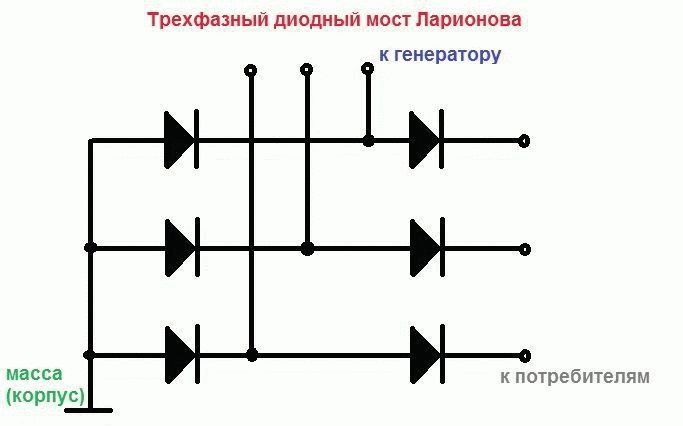
The diagram shows:
- Three diodes ring in pairs with zero resistance between the cathode (negative polarity) and the anode (positive polarity). This is where the generator terminals go.
- Two triplets of diodes (lying in the same crescent plane) ring among themselves by cathodes or anodes. Depending on which electrode produces a short circuit, the branch is determined - load or going to ground.
Having created the correct layout of the electrical connections, they begin to test each diode separately. The branch going to ground is tested from the generator side, the other - from the load side. The direction is known from Larionov's scheme. We check the diode bridge with a multimeter, touching the base of the black arrow (see figure) of each element with the red probe, and the tip of the same element with the black one. At the same time, they check the insulation of the contacts with the sickle-shaped planes, incl. neighboring. Based on the data obtained, the need to continue troubleshooting is assessed.
Conclusion: the diode, without soldering, is checked with a multimeter on a rough structure like a car generator bridge. Ringing the electronic board is more difficult. Any check is carried out with special shaped probes. For rough designs, crocodile grips are taken, the motherboard is checked with thin needle-shaped probes. In the latter case, there is a chance to ring the diode with a multimeter on the board under voltage with the risk of burning the tester.
Hopefully, the reader now understands how to test a diode with a multimeter.


