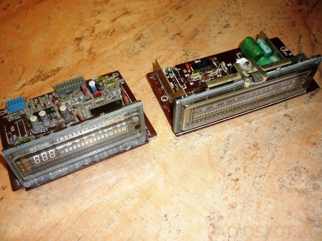
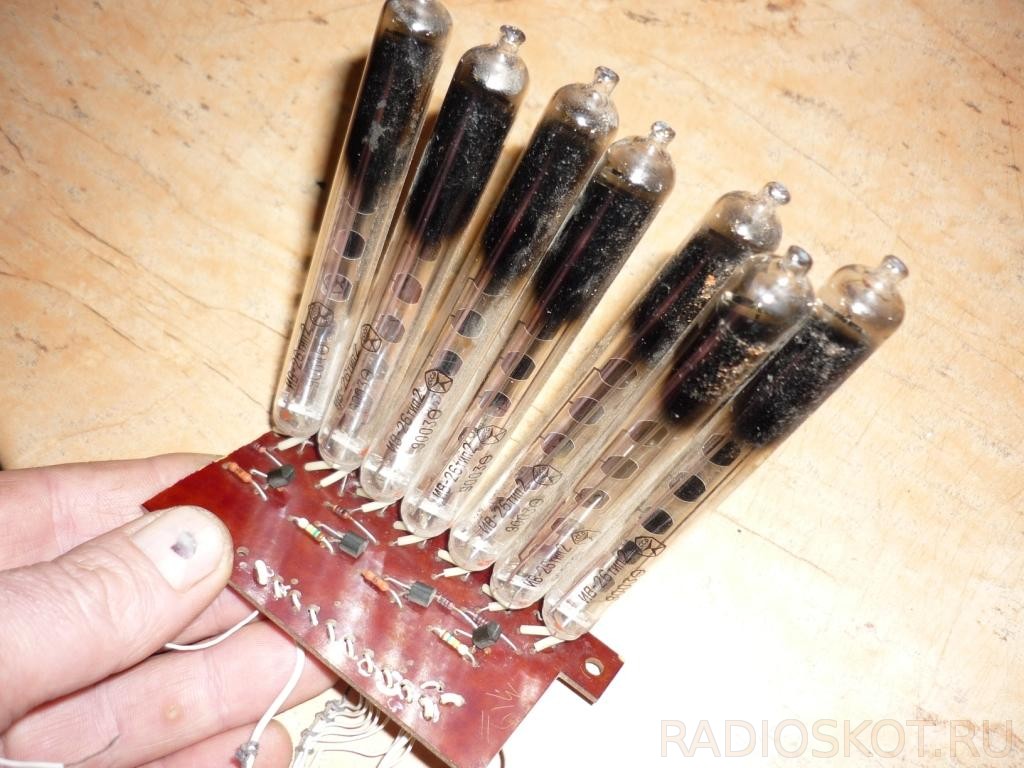
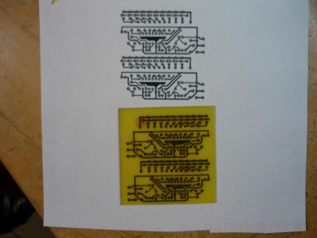
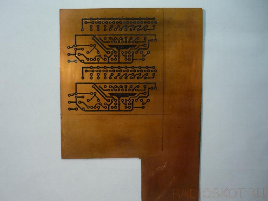
Hello to all DIYers! Somehow, sorting out my stocks, I came across two luminescent indicators from Soviet tape recorders. One turned out to be a worker. I decided to do something unusual with him. Well, then it started ... I decided to assemble the second sound indicator on microcircuits in the form of arrows from LEDs, but the third of the IV-26 vacuum indicators from an industrial electronic clock, and put the whole thing into a case. For the LM3915, I etched two boards (one for LEDs), the LEDs in the smd case were removed from the LED strip, I assembled the boards - turned on - everything worked fine. For IV-26, it was necessary to use indicator kerchiefs from a Chinese radio tape recorder on an AN6884 microcircuit. The case remained behind the body, cut out panels from fiberboard, glued them together using wooden blocks and Moment glue. I cut out a window for the indicators in the case. Putty, cleaned and pasted over with black foil. The false panel was cut from the profile from under the drywall. Since the power supply needed 5 different voltages (+12 -12 26 3.5 6.3 volts), I did not wind the transformer - I rummaged in the bins and found suitable transics and soldered the simplest stabilizers to them. The whole thing was fixed in the case with hot melt glue. The general switch and level regulator are located at the back of the structure. For the front panel, I cut out a plate of glass, drilled 3 holes for the switches. Tinted glass would have been more beautiful, but I did not find it, I think I will tint it with a car film. Now look at the photo report and videos of the indicators, especially for our beloved site site :-)
Schematic diagrams of AF indicators
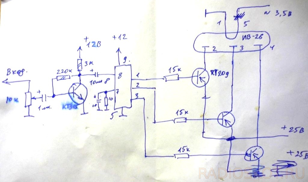
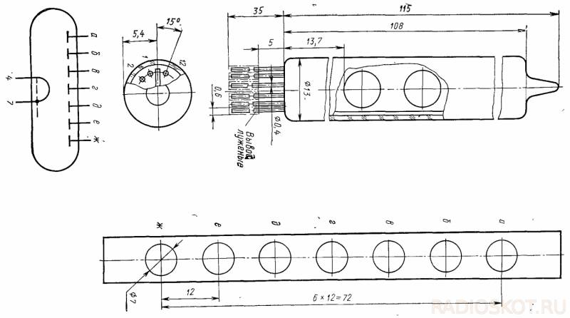
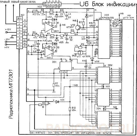
Photo of the manufacture of the structure