Since the LED is a semiconductor device, the polarity must be observed when connected to the circuit. The LED has two outputs, one of which is the cathode ("minus"), and the other is the anode ("plus").
The LED will be on only when directly connected, as shown in the figure
When turned back on, the LED will not light up. Moreover, the failure of the LED is possible at low allowable values of the reverse voltage.
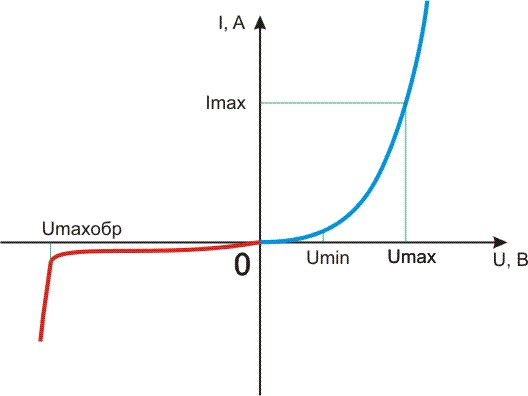
The dependences of current on voltage for direct (blue curve) and reverse (red curve) inclusions are shown in the following figure. It is not difficult to determine that each voltage value corresponds to its own amount of current flowing through the diode. The higher the voltage, the higher the current value (and the higher the brightness). For each LED, there are permissible values of the supply voltage Umax and Umaxrev (respectively for direct and reverse switching). When voltages above these values are applied, an electrical breakdown occurs, as a result of which the LED fails. There is also a minimum value of the supply voltage Umin, at which the LED glows. The range of supply voltages between Umin and Umax is called the "working" zone, since this is where the operation of the LED is ensured.
1. There is one LED, how to connect it correctly in the simplest case?
In order to properly connect the LED in the simplest case, you need to connect it through a current-limiting resistor.
Example 1
There is an LED with an operating voltage of 3 volts and an operating current of 20 mA. It must be connected to a 5 volt source.
Calculate the resistance of the current limiting resistor
R = Uquenching / ILED
Uquenching = Upower - ULED
Usupply = 5 V
ULED = 3V
ILED = 20mA = 0.02A
R \u003d (5-3) / 0.02 \u003d 100 Ohm \u003d 0.1 kOhm
That is, you need to take a resistor with a resistance of 100 ohms
P.S. You can use the on-line LED resistor calculator
2. How to connect multiple LEDs?
We connect several LEDs in series or in parallel, calculating the required resistance.
Example 1
There are LEDs with an operating voltage of 3 volts and an operating current of 20 mA. It is necessary to connect 3 LEDs to a source of 15 volts.
We make a calculation: 3 LEDs for 3 volts \u003d 9 volts, that is, a 15 volt source is enough to turn on the LEDs in series
The calculation is similar to the previous example.
R = Uquenching / ILED
Usupply = 15 V
ULED = 3V
ILED = 20mA = 0.02A
R \u003d (15-3 * 3) / 0.02 \u003d 300 Ohm \u003d 0.3 kOhm
Example 2
Let there be LEDs with an operating voltage of 3 volts and an operating current of 20 mA. It is necessary to connect 4 LEDs to a source of 7 volts
We make a calculation: 4 LEDs for 3 volts \u003d 12 volts, which means we do not have enough voltage to connect the LEDs in series, so we will connect them in series-parallel. Let's divide them into two groups of 2 LEDs. Now we need to calculate the current-limiting resistors. Similarly to the previous paragraphs, we calculate the current-limiting resistors for each branch.
R = Uquenching / ILED
Uquenching = Upower - N * ULED
Usupply = 7 V
ULED = 3V
ILED = 20mA = 0.02A
R \u003d (7-2 * 3) / 0.02 \u003d 50 Ohm \u003d 0.05 kOhm
Since the LEDs in the branches have the same parameters, the resistances in the branches are the same.
Example 3
If there are LEDs of different brands, then we combine them in such a way that each branch has LEDs of only ONE type (or with the same operating current). In this case, it is not necessary to observe the same voltages, because we calculate our own resistance for each branch.
For example, there are 5 different LEDs:
1st red voltage 3 volts 20 mA
2nd green voltage 2.5 volts 20 mA
3rd blue voltage 3 volts 50 mA
4th white voltage 2.7 volts 50 mA
5th yellow voltage 3.5 volts 30 mA
Since we divide the LEDs into groups by current
1) 1st and 2nd
2) 3rd and 4th
3) 5th
we calculate resistors for each branch:
R = Uquenching / ILED
Uquenching = Upower - (ULEDY + ULEDX + ...)
Usupply = 7 V
ULED1 = 3 V
ULED2 = 2.5 V
ILED = 20mA = 0.02A
R1 = (7-(3+2.5))/0.02 = 75 Ohm = 0.075 kOhm
likewise
R2 = 26 Ohm
R3 = 117 Ohm
Similarly, you can arrange any number of LEDs
IMPORTANT NOTE!!!
When calculating the current-limiting resistance, numerical values \u200b\u200bof which are not in the standard series of resistances are obtained, THEREFORE, we select a resistor with a resistance slightly larger than calculated.
3. What happens if there is a voltage source with a voltage of 3 volts (or less) and an LED with an operating voltage of 3 volts?
It is acceptable (BUT NOT DESIRABLE) to include an LED in a circuit without current-limiting resistance. The disadvantages are obvious - the brightness depends on the supply voltage. It is better to use dc-dc converters (voltage boost converters).
4. Is it possible to turn on several LEDs with the same operating voltage of 3 volts in parallel to each other to a source of 3 volts (or less)? In the "Chinese" lanterns, this is exactly what is done.
Again, this is acceptable in amateur radio practice. The disadvantages of this inclusion: since the LEDs have a certain spread in parameters, the following picture will be observed, some will glow brighter, while others will be dimmer, which is not aesthetic, which is what we observe in the flashlights above. It is better to use dc-dc converters (voltage boost converters).


