Very often there is a need to control the brightness of the lamp within a certain value, usually from 20 to 100% brightness. It does not make sense to do less than 20%, since the lamp will not give a luminous flux, but only a weak glow will occur, which can only be useful for decorative purposes. You can go to the store and buy a finished product, but now these devices are valuable, to put it mildly, inadequate. Since we are jacks of all trades, we will make these devices with our own hands. Today we will consider several schemes, thanks to which it will become clear to you how to make a dimmer for 12 and 220 V with your own hands.
On triac
To begin with, consider the circuit of a dimmer switch operating from a 220 volt network. This type of device works on the principle of phase shift opening the power key. The heart of the dimmer is an RC chain of a certain denomination. Control pulse generation unit, symmetrical dinistor. And actually the power switch itself, the triac.
Let's consider how the circuit works. Resistors R1 and R2 form a voltage divider. Since R1 is variable, it changes the voltage in the R2C1 chain. The DB3 dinistor is connected to a point between them, and when the voltage of its opening threshold on the capacitor C1 is reached, it fires and sends a pulse to the triac VS1 power switch. It opens and passes current through itself, thereby turning on the network. The position of the regulator determines at what moment the phase wave will open the power switch. It can be 30 volts at the end of the wave, and 230 volts at the peak. Thus, supplying some of the voltage to the load. The graph below shows the process of controlling lighting with a dimmer on a triac.

On these graphs, the value (t*) is the time it takes for the capacitor to charge to the opening threshold, and the faster it gains voltage, the sooner the key turns on, and the more voltage is on the load. This dimmer circuit is simple and easy to repeat in practice. We recommend watching the video below, which clearly shows how to make a dimmer on a triac:
1000W Triac Power Regulator
On thyristors
If you have a bunch of old TVs and other things gathering dust in the bins of crazy people, you can not buy a triac, but make a simple thyristor dimmer. The circuit is slightly different from the previous one, in that each half-wave has its own thyristor, and thus its own dinistor for each key.

Let us briefly describe the regulation process. During the positive half-wave, the capacitance C1 is charged through the chain R5, R4, R3. When the opening threshold of the dinistor V3 is reached, the current through it enters the control electrode V1. The key opens by passing a positive half-wave through itself. With a negative phase, the thyristor is locked, and the process is repeated for another key V2, charging through the chain R1, R2, R5.
Phase regulators - dimers can be used not only to adjust the brightness of incandescent lamps, but also to control the speed of rotation of the exhaust fan, make an attachment for the soldering iron and thus regulate the temperature of its tip. Also, with the help of a homemade dimmer, you can adjust the speed of a drill or vacuum cleaner and many other applications.
Video assembly instruction:
Assembling a thyristor dimmer
Important! This control method is not suitable for fluorescent, economical compact and LED lamps.
Condenser dimmer
Along with smooth regulators, capacitor devices have become widespread in everyday life. The operation of this device is based on the dependence of the transfer of alternating current on the value of the capacitance. The larger the capacitance of the capacitor, the more current it passes through its poles. This type of homemade dimmer can be quite compact, and depends on the required parameters, the capacitance of the capacitors.

As can be seen from the diagram, there are three positions of 100% power, through the quenching capacitor and off. The device uses non-polar paper capacitors, which can be obtained in old technology. About that, we told in the corresponding article!
Below is a table with the capacitance-voltage parameters on the lamp.
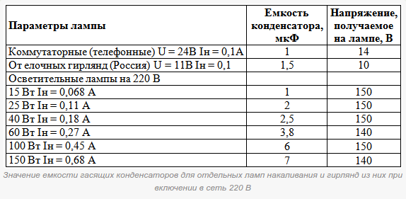
Based on this scheme, you can assemble a simple night light yourself, use a toggle switch or switch to control the brightness of the lamp.
On a chip
To regulate the power to the load in 12 volt DC circuits, integral stabilizers - KRENKs are often used. The use of a microcircuit simplifies the development and installation of devices. Such a homemade dimmer is easy to set up and has protection functions.

With the help of a variable resistor R2, a reference voltage is created at the control electrode of the microcircuit. Depending on the set parameter, the output value is adjusted from a maximum of 12V to a minimum of tenths of a Volt. The disadvantage of these regulators is the need to install an additional radiator for good cooling of the KREN, since part of the energy is released on it in the form of heat.
This dimmer was repeated by me and did a great job with a 12 Volt LED strip, three meters long and the ability to adjust the brightness of the LEDs from zero to maximum. For not very lazy craftsmen, we can offer to make a dimmer at home on an integrated timer 555, which controls the power switch KT819G, short PWM pulses.
In this mode, the transistor is in two states: fully open or fully closed. The voltage drop across it is minimal and allows the use of a circuit with a small radiator, which compares favorably with the previous circuit with a KREN regulator in terms of dimensions and efficiency.


