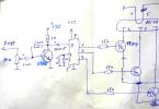
The first version of the flashlight circuit
In tests, this circuit showed incredible stability within the supply voltage of 3.7-14 volts (but be aware that efficiency decreases with increasing voltage). As I set 3.7 volts at the output, it was so in the entire voltage range (we set the output voltage with resistor R3, when this resistance decreases, the output voltage increases, but I do not advise you to reduce it too much, if you experiment, calculate the maximum current on the LED1 LED and the maximum voltage on the second) . If we feed this circuit from Li-ion batteries, then the efficiency is approximately 87-95%. Ask, why then came up with PWM? If you don't believe me, check it out for yourself.
At 4.2 volts efficiency = 87%. At 3.8 volts efficiency = 95%. P=U*I
The LED consumes 0.7A at 3.7 volts, which means 0.7 * 3.7 = 2.59 W, subtract the voltage of a charged battery and multiply by the current consumption: (4.2 - 3.7) * 0.7 = 0.35W. Now let's find out the efficiency: (100/(2.59+0.37)) * 2.59 = 87.5%. And half a percent for heating the remaining parts and tracks. Capacitor C2 - soft start for safe turning on of the LED and protection against interference. Be sure to install a powerful LED on a radiator, I used one radiator from a computer power supply. Parts location:

The output transistor should not touch the back metal wall to the board, put paper between them or draw a drawing of the board on a sheet of notebook and make it the same as on the other side of the sheet. To power the LED flashlight, I used two Li-ion batteries from a laptop battery, but it is quite possible to use telephone batteries, it is desirable that their total current be 5-10A * h (we connect in parallel).
Let's proceed to the second version of the diode lamp

I sold the first flashlight and felt that without it it was a little annoying at night, and there were no details to repeat the previous scheme, so I had to improvise from what was at that moment, namely: KT819, KT315 and KT361. Yes, even on such details, it is possible to assemble a low-voltage stabilizer, but with slightly higher losses. The scheme resembles the previous one, but in this one everything is quite the opposite. Capacitor C4 here also smoothly supplies voltage. The difference is that here the output transistor is open with resistor R1 and KT315 closes it to a certain voltage, while in the previous circuit the output transistor is closed and opens second. Parts location:

I used it for about six months, until the lens cracked, damaging the contacts inside the LED. He was still working, but only three cells out of six. Therefore, I left as a gift :) Now I’ll tell you why such good stabilization using an additional LED. For those who are interested, we read it, it can be useful when designing low-voltage stabilizers, or we skip it and move on to the last option.
So, let's start with temperature stabilization, whoever conducted the experiments knows how important it is in winter or summer. So, in these two powerful flashlights, the following system operates: as the temperature increases, the semiconductor channel increases, allowing more electrons to pass through than usual, so it seems that the channel resistance decreases and therefore the current passing increases, since the same system operates on all semiconductors, the current through the LED also increases by closing all transistors to a certain level, that is, stabilization voltage (experiments were carried out in the temperature range of -21 ... +50 degrees Celsius). I collected a lot of stabilizer circuits on the Internet and wondered "how could such mistakes be made!" Someone even recommended their own scheme for powering the laser, in which 5 degrees of temperature rise prepared the laser for ejection, so consider this nuance too!
Now about the LED itself. Anyone who has played with the supply voltage of LEDs knows that as it increases, the current consumption also increases dramatically. Therefore, with a slight change in the output voltage of the stabilizer, the transistor (KT361) reacts many times easier than with a simple resistor divider (which requires a serious gain), which solves all the problems of low-voltage stabilizers and reduces the number of parts.
The third version of the LED lamp
Let's proceed to the last scheme considered and used by me until today. The efficiency is greater than in previous schemes, and the brightness of the glow is higher, and naturally, I bought an additional focus lens for the LED, and there are already 4 batteries, which approximately equals the capacity of 14A * hour. Principal email. scheme:

The circuit is quite simple and assembled in SMD design, there is no additional LED and transistors that consume excess current. For stabilization, TL431 was used and this is quite enough, the efficiency here is from 88 - 99%, if you don’t believe it, count it. Photo of the finished homemade device:


Yes, by the way, about the brightness, here I allowed 3.9 volts at the output of the circuit and have been using it for more than a year, the LED is still alive, only the radiator heats up a little. But whoever wants to can set a lower supply voltage for himself by selecting the output resistors R2 and R3 (I advise you to do this on an incandescent lamp, when you get the result you need, connect the LED). Thank you for your attention, Lefty Lesha (Stepanov Alexey) was with you.
Discuss the article POWERFUL LED FLASHLIGHTS


