The considered designs and circuits of the turn signal relays are intended to replace or modernize existing, but insufficiently competent solutions

This circuit is designed to work only with LEDs in your car's brake lights, if you are using conventional bulbs see the diagrams below. Additional contacts are used to power the LEDs for turning left and right.

The circuit of this homemade turn signal relay is quite simple and it can be assembled on a homemade printed circuit board, the drawing of the latter for the program can be downloaded from the green arrow above.
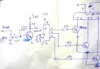
Power supply 10 ... 20 V is connected to the POWER contacts in any polarity (it is convenient to connect it between the wires going to the lamps of the right and left turns). A small speaker (0.25 ... 1 W, 4 ... 20 Ohm) is connected to the SPEAK contacts. In series with the speaker, you can install a variable resistor with a resistance of 200 ... 800 Ohm to adjust the volume (or choose the resistance of the resistor R2)


Almost any transistors are low-power, with the exception of Q3, which must be designed for an average current of more than 250 mA (the same as diodes D1 ... D4).
Numbering of pins of transistors on a printed circuit board: 1 - emitter; 2 - base; 3 - collector. The printed circuit board of the turn signal indicator has dimensions of 48.9x37.5 mm. The location of the elements on the printed circuit board is shown in Figure 2. The drawing of the board from the side of the printed conductors is shown in Figure 3, from the side of the elements - in Figure 4
In a new era of energy saving, the use of LEDs instead of car lamps has become relevant. They are able to work much longer and consume less energy. And therefore, less current flows through the turn relay circuit, and in the case of using LEDs, the blinking frequency changes, because the frequency of operation of the relay is related to the load resistance .. When the load resistance increases, which is exactly what happens when one of the lamps burns out or opens, the relay starts often.
This circuit is intended to modernize the standard turn signal relay to operate at the frequency we need.
Relay 495.3747 is installed on the entire VAZ line starting from 2108 and on most of the GAZ produced.
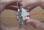
To modify the relay, we open the case. To do this, take a flat screwdriver and remove the case cover by pulling back the plastic latches on both sides at the same time.

Let's move on to understanding the operation of the schematic diagram 495.3747

We connect the mass to the 31st contact, 49, 49a to the lamps. R3 is a limiting resistor. R1 and C11 set the output frequency. The microcircuit can be not only U9043, but also other analogs, such as the domestic KR1055GP1B.
To change the frequency in the case of connecting LEDs, it is enough to increase the capacitance of the capacitor to 4.7 microfarads, but the alarm does not work correctly. And in order to avoid this, it is enough to interrupt the contact from pin 7.
The only problem with this LED upgrade will be the lack of control over burned-out LEDs, but they are reliable enough anyway.

For especially forgetful drivers and blondes in small red cars, I suggest assembling a sound signaling circuit. The device is assembled on the widespread and cheap K155LA3 microcircuit and is connected to the indicator lamp of the turn signal or handbrake in accordance with.


