If not all, then many motorists are familiar with the situation when the direction indicator relay begins to change the frequency of its operation when the lamp in the direction indicator burns out. The frequency of operation of the relay is tied to the load resistance, that is, to the installed lamps. With an increase in the load resistance, which exactly happens when one of the lamps burns out or opens, the relay starts to operate most often. The same effect is observed when installing LEDs in direction indicators, since their power consumption is less, which means much more resistance.
After studying the material in this article, you can modify the standard turn signal relay for LEDs so that it works with the frequency you need.
First of all, a little about the standard relay. The 3-pin turn signal relay, which will be discussed, is installed on cars from VAZ 2108 to the present, that is, on VAZ 2109, 2110, 2111, 2112, Lada Priora, Lada Kalina, GAZ cars. Marking 495.3747, possibly 495.3747-01.
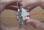
To modify the relay, it will be necessary to open the case. To do this, take a flat-blade screwdriver and remove the housing cover by pulling back the plastic latches from two opposite sides
A diagram of a standard relay is shown on the relay body, although it is difficult to call it a diagram (no ratings, no other designations are indicated)

As a result, a normal circuit diagram is shown below:

Now let's figure out what is responsible for what in this circuit and how we can change the work so that the frequency of operation of the direction indicators does not change with an increased load. The first is the connection. Ground is connected to pin 31. 49a - output to lamps, 49 - input "+" from the direction indicator switch.
R3 - resistor limiting the current to the control base of the transistor in the microcircuit; R1 and C11 - it is these radio elements that are responsible for the frequency of the output signal from leg 3 of the microcircuit. From leg 3, power is supplied by the relay coil; Conclusion 7 is also an interesting conclusion. The output controls the change in resistance and, accordingly, the voltage on contact 49 a. It is he who gives the command to the microcircuit to change the frequency when the lamps burn out.
Now, presenting the functional purpose of the relay elements, it is easy to decide on measures to maintain the frequency of the turn indicators when their internal resistance changes, that is, for example, when installing LEDs.
It is possible to change the capacitance rating, double it (replacing it with a 4.7 uF capacitor instead of 2.2 uF - in the photo the capacity is increased due to the parallel connection of an additional capacitor to the standard one),

but at the same time, incorrect operation of the alarm is observed. It will operate at half the frequency. The variation in resistance is also not entirely successful. Since, in fact, here you will have to empirically select a current limiting resistor at pin 4, it is also not a very good option.
There remains the last and perhaps the best way out. In fact, remove the control over the load resistance. By cutting the foil on the printed circuit board (red line) going to pin 7 of the microcircuit, we get a frequency-stable operation of the direction indicators.

The only drawback of such a modification of the relay for LEDs will be the absence of burned-out LEDs behind the control, since we have actually removed the dependence of the frequency on the load resistance.
And of course, lastly, I would like to say that at present, due to the demand for a similar product, in particular, turn signal relays for LEDs, you can find ready-made solutions in car dealerships or online stores. That is, to purchase a relay already specialized for working with LEDs, their cost will be about $ 10


