The directions of tuning a modern car are varied: the list includes the use of xenon lamps, the installation of overlays on the headlights, and an aerodynamic body kit ...
We will dwell on the practice of using LEDs in direction indicators of domestically produced cars.
Expected Installation Difficulties
The fashion for embedding LED lamps in cars came quickly, and significant "pitfalls" during their re-equipment were immediately discovered. Regarding the turns of cars of the VAZ family (in particular the VAZ-2110), they are manifested in the fact that the frequency of blinking of turn signal headlights increases.
The reasons for this phenomenon are as follows: LEDs operate at higher resistance values in comparison with conventional lamps. Therefore, with this inclusion, they heat up more intensely. As a result, the plate simply heats up, as a result of which the electrical circuit is opened.
When the light bulb burns out, the resistance drops sharply, resulting in an increased flashing rate of the warning light. You can replace an ordinary lamp with an LED, but this fundamentally does not change anything, so you have to modify the turn relay for the LEDs with your own hands.
Solution options
The solution to the problem in the video is described in great detail and in a high quality, and below we will analyze all the options in more detail:
- In parallel with the LEDs, a ballast resistor can be included in the relay circuit (the choice depends on the type of car, for the VAZ-2110, for example, it is 2.2 kOhm);
- Instead of a resistor, simply add a conventional lamp in parallel;
- In the circuit, replace the capacitor with a more capacitive one;
- In parallel with the existing one, you can solder another capacitor with the same capacity.
Each of the options has its own pros and cons. For example, in the presence of a ballast resistor, the electrical circuit of the direction indicator relay will simply increase its power consumption, which will affect the battery life. The resistors will heat up and this will lead to a decrease in the light output of conventional lamps.
Parallel connection of one more lamp is fraught with the difficulties of its safe installation in the same housing. By adding an additional capacitor to the circuit, you will have to come to terms with the fact that the flashing frequency of the direction indicator will significantly decrease (however, in the current rules, there are no restrictions on the flashing frequency of the LEDs).
Modification of the relay circuit
The number of LEDs installed in series can be determined empirically, but in practice, 5 pieces are enough: such a load is quite enough for the circuit to operate. At the same time, the circuit on the board is opened, which allows it to work with both conventional and LED lamps. However, in that case, the device will not be able to signal that the direction indicator light has burned out.
The refinement algorithm is considered on the example of a relay that operates using the U643B controller manufactured by the Chinese company Atmel. Such controllers are often used in electronic circuits of modern passenger cars.
One of the functions of such a controller is to warn of a malfunction of the direction indicator lamps. The criterion for a malfunction is a critical decrease in the current in the circuit, as a result of which the flashing frequency increases sharply.
Diagram of an electronic turn relay for LEDs
The operating value of the LED current is set at the output of the controller circuit “Lamp failure detection”. The nuance is that the efficiency of LED lamps is much higher than that of conventional lamps. The inconvenience lies in the fact that the current consumption decreases, and the increased flickering of the LEDs is perceived by the controller as a failure of the turn relay.
In order to get rid of such a drawback, you just need to replace the resistor R3 of the circuit with a more powerful one. This will lead to an increase in the total load, and a corresponding increase in the current strength - to values at which there will be no more blinking of the turn signals.
An alternative solution for some motorists is that the section of the circuit that is responsible for measuring the current is cut out in the circuit. However, there is also a serious problem in that action.
Since the U643B controller works with its initial parameters already set by the manufacturer, then with this "tuning" of the direction indicator, you can accidentally change the so-called Device Code - the code for identifying the controller by external devices. It is impossible to reflash it. In addition, by cutting out one of the contacts in the turn signal relay circuit, you can get frequent blinking of the turn signals, which does not always satisfy the car user.
Reverse recovery, most likely, will do nothing, since the relay controller has already "memorized" its new parameters and changed the Device Code.
The difficulty in adjusting the parameters of the resistor R3 lies in the fact that the part works with initially small resistance values, therefore accurate instruments will be required for adjustment, however, from a technical point of view, this approach is more correct.
Limitations and procedure for modifying the turn relay
Installation of LEDs is only possible if the relays are digital. For cars of the VAZ or GAZ family, these are devices marked with the designation 494.3747 (for comparison: the analog designation is 231.3747). When there is no marking, the class of the relay is quite simply determined by its dimensions, which are much larger for the analog version. If it is analogue that works in the car, you will have to purchase a digital one.
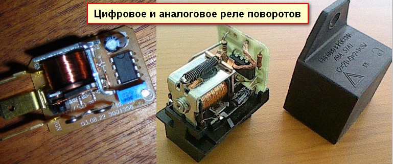 Appearance of digital and analog relay turns
 The direction indicator is being finalized in the following sequence:
- The case is opened;
- The location of the chip responsible for the turn signals is installed: it is usually located to the right of the external board.
- The capacitor is replaced, which determines the frequency of the blinking generator of the turn signal lamp. The subtlety lies in the fact that the capacitance of the capacitor should be within 4.7 μF per 50 V operating voltage. Alternatively, you can put another capacitor, in most cases the space inside the relay housing allows you to perform this operation.
- The output parameters are monitored with the help of measuring devices. In the event that the LEDs are functioning properly, the case is replaced in its original place.
As additional items, you should purchase:
- P-channel transistor;
- A resistor from the above resistance range (if it is soldered into the circuit, not a capacitor);
- LEDs (preferably red or orange).
Soldering of such a modernized version of the relay can be done using the usual hinged method, on top of the main circuit.


