From time to time, questions arise with the turn signal relay, when a motorcycle, and not only a motorcycle, but also a car, put LED lamps in the turn signals, or change the turn signals themselves entirely to LED ones. Regular relays, as a rule, refuse to work with such bulbs, because the load is too small for them. It (relay) perceives led lamp, like a broken wire and starts switching faster than usual. Under normal conditions, this is convenient: the relay began to “click” faster than usual, therefore, some kind of light bulb burned out. But for someone who has deliberately replaced incandescent bulbs with LEDs, this is the beginning of a headache. A few years ago, electronic turn relays for LEDs cost about 500 rubles, which is not at all humane. I just needed a relay for the LEDs. After scouring the Internet, I found an article about converting a conventional automotive three-pin electronic turn signal relay into a relay for LEDs. I did everything as described, everything worked, I forgot. But, in Lately, apparently, spring is affecting, the question of a relay for LEDs often began to pop up.
Who is interested, please under the cat.
Compared to what it was a few years ago. the situation seems to have improved. So, literally today, while chatting here with one of the members of the forum, who ordered a special turn relay for LEDs, I found out that the prices for these relays have fallen. According to this forum member, he ordered a relay for 170 rubles. Today, I bought an ordinary car relay in a car shop for the same 170 rubles. I suppose that I could find cheaper, because. this store is far from the cheapest, but I live in small town, there are few stores, I went to another store, the relays ran out there. And to go somewhere else because of a win of 10-20 rubles ... I don’t see the point.
So, let's move on to the change.
To understand what exactly and how we will redo it, I will give a relay diagram:
The basis of the relay is a specialized integrated (on a microcircuit) pulse generator that controls the closing and opening of a small-sized relay. The microcircuit has a special output that monitors the voltage drop across the shunt. This drop depends on the total resistance of the connected (parallel) lamps. If a lamp burns out, the resistance increases, the voltage drop across the shunt decreases, and the microcircuit starts switching faster. If this output of the microcircuit is turned off, it will give pulses at a constant frequency, regardless of the number and power of the connected lamps, just what we need.
In the diagram, the output to be disabled is crossed out.
Now let's move on to practical implementation.
I bought a relay like this: 
A wide strip of metal is like the same shunt.
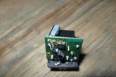
View of the circuit board: 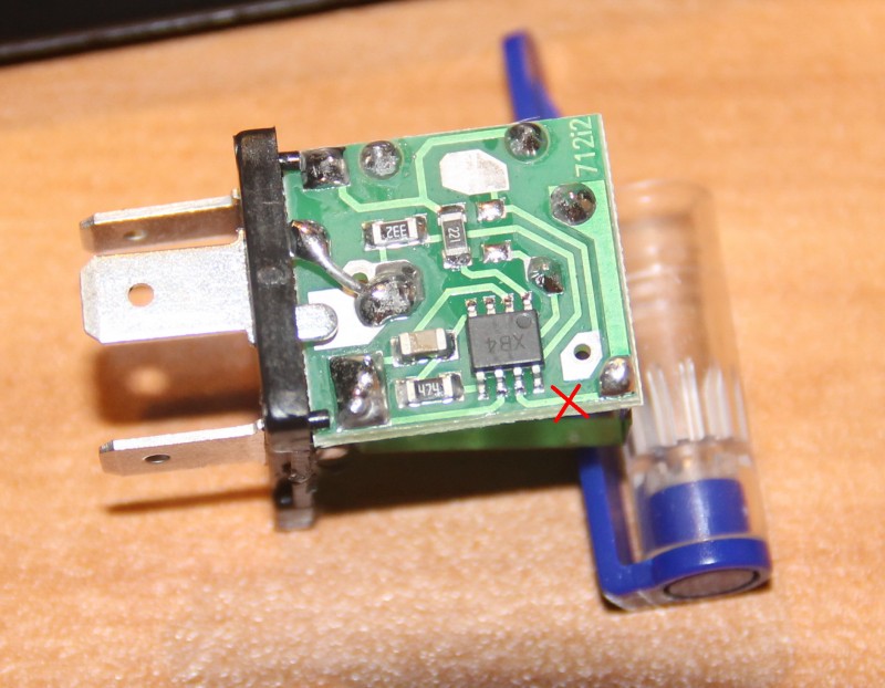
We see a microchip. There is a dot on her body, she is always in the corner. This dot calls the key. The key is always placed at the first output of the microcircuit. The pins are numbered sequentially counterclockwise. If we return to the scheme, we need output number 7. I crossed out the conductor coming from him. This optimal location to cut the conductor. If someone buys another relay, or rather, another manufacturer, the insides can appearance differ. Therefore, I explain in such detail how to find the right conductor. I cut the track on the board with the tip of an ordinary knife, scratched it several times, saw that instead of a copper track, the board was visible and that was enough. The current there is scanty, it will not break through. 
The incision site is circled.
I want to draw the attention of those who have a standard two-contact relay. On the old Yamaha R1-Z it was just like that. Don't be scared! There's just no mains wire.
Relay connection.
The relay has 3 outputs:
39 - ground, always connected.
49 - permanent +, connected when the ignition is turned on
49a - signal, goes to the remote control to the turn switch and to the emergency gang.
To connect, you need to determine where which wire is in the standard wiring. If there is a circuit - good, if not, you need a probe lamp.
First, let's find the mass. One output of the probe lamp is on + battery, the other is trying the wires in the connector. Turn signal switch and hazard lights must be off. Where the lamp caught fire, that conclusion is the mass one. We connect the wire of the probe lamp to any ground contact and try the wires in the connector, while not forgetting to turn on the ignition. But, the lamp can light up in both wires (depending on the connection diagram of the control lamp in the tidy), so we turn on any turn signal or emergency lights. The wire where the probe caught fire is the required +. The remaining wire is signal. You can check it if you close the wire + and signal with the turn signals on, or an emergency gang. Turns should light up. If anyone is afraid, you can connect these 2 wires with a probe lamp, then the turn signals will light up, but dimly, and the probe is only slightly worse than when connected to a battery. And all because we turned on the turn signals in series with the probe.
If you don't understand something, ask and I'll try to answer. But I'm leaving for the weekend, so there may be a delay with the answers.
P.s. took a video with the converted relay connected. Anyone interested, please
Now LEDs are installed everywhere and everywhere and not many people know that when installing LEDs in the VAZ 2110 turn signals, there will be problems with blinking. The direction indicators will start signal much faster. Why is this happening and how to fix it.
First you need to figure out How does the turn signal relay work?(relay number 3 in the fuse box), and many other cars too ..
talking in simple words
: When the light in the turn signals works, the plate in the relay heats up due to the resistance of the light and opens the circuit. And when the light bulb burns out, then the resistance of the light bulb becomes insufficient in the relay, heating does not occur, the circuit does not open and, as a result, frequent blinking.
That is, when turn signals flashing fast- This is a signal to us that it is time to replace the light bulb.
Exactly the same situation occurs with frequent blinking when you put in turn signals LEDs instead of light bulbs.
Because the relay does not have the required resistance, then it works out in emergency mode.
The same problem appears after replacement of marker lamps with diodes. It's also the fault of the relay.
You can solve this problem in different ways, I will tell you in order:
Installing an additional resistor in the turn relay
In order to fool the relay, you can solder a resistor in parallel with the LEDs(selected experimentally, approximately 2.2 kOhm).
Thus, this resistor will simulate the load of the lamp.
You can do something simple (you can even say 'collective farm') it's just to connect standard lamps in parallel with the LEDs 🙂
Minuses- heating of resistors, incandescent lamps will shine a little worse.
Capacity increase
To cure frequent blinking turns with LEDs installed replace the capacitor in the turn signal relay.
Solder the old capacitor and solder the new one in its place. Be careful with the polarity, do not mix it up!
That is, by increasing the capacitance of the capacitor by 2 times, you will make blinking 2 times less.
If you can't find a capacitor larger capacity, then one can find the same solder it like a second capacitor 🙂
Minuses- 'Estonian' emergency gang (it will blink slowly 🙂) 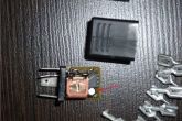
LEDs soldered in series 
Some argue that if solder 5 LEDs in series in the turn signal, then their load should be enough to open the circuit. If anyone has tried and works, then let him confirm.
Open the circuit in the turn signal relay
You can do very in a simple way. Just take and open the circuit on the turn signal relay board.
That is, the relay will work with both conventional lamps and LEDs.
The downside of this approach- the relay will no longer signal you that your turn signal has burned out. 

Buy a turn signal relay for LEDs
Buy alternative turn signal relay for tens which is done specially for LED.
You can order, for example, on the website 12v.ru. 

The considered designs and circuits of the turn relay are intended to replace or upgrade existing, but not sufficiently competent solutions.

This circuit is designed to work only with the LEDs in your car's brake lights, if you are using regular bulbs see the circuits below. Auxiliary contacts are used to power the left and right turn LEDs.

The circuit of this homemade turn relay is quite simple and can be assembled on a homemade printed circuit board, you can download the last picture for the program by the green arrow above.
10 ... 20 V power is connected to the POWER contacts in any polarity (it is convenient to turn it on between the wires going to the bulbs of the right and left turns). A small speaker (0.25 ... 1 W, 4 ... 20 Ohm) is connected to the SPEAK contacts. In series with the speaker, you can install a variable resistor with a resistance of 200 ... 800 Ohms to control the volume (or choose the resistance of the resistor R2)


Almost any low-power transistors, with the exception of Q3, which must be rated for average current more than 250 mA (same as diodes D1...D4).
The numbering of the outputs of transistors on the printed circuit board: 1 - emitter; 2 - base; 3 - collector. The printed circuit board of the turn signaling device has dimensions of 48.9x37.5 mm. The location of the elements on the printed circuit board is shown in Figure 2. The pattern of the board from the side of the printed conductors is shown in Figure 3, from the side of the elements - in Figure 4
V new era energy saving, the use of LEDs instead of car lamps. They are able to work much longer and consume less energy. And therefore, less current flows through the turn relay circuit and in the case of using LEDs, the blinking frequency changes, because the periodicity of the relay operation is related to the load resistance .. When the load resistance increases, which is exactly what happens when one of the lamps burns out or opens, the relay starts to work most often.
This circuit is designed to upgrade the standard turn signal relay to operate at the frequency we need.
Relay 495.3747 is installed on the entire VAZ line starting from 2108 and on most manufactured GAZ.
To refine the relay, we open the case. To do this, take a flat screwdriver and remove the housing cover by pulling the plastic latches simultaneously from both sides.
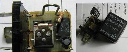
Let's move on to work circuit diagram 495.3747

We connect ground to pin 31, 49, 49a to lamps. R3 - limiting resistor. R1 and C11 set the frequency of the output signal. The microcircuit can be not only U9043, but also other analogues, for example, domestic KR1055GP1B.
To change the frequency in the case of connecting LEDs, it is enough to increase the capacitance of the capacitor to 4.7 microfarads, but the alarm does not work quite correctly. And in order to avoid this, it is enough to interrupt the contact from pin 7.
The only problem with such an LED upgrade would be the lack of control of burned out LEDs, but they are already quite reliable.

For especially forgetful drivers and blondes in small red cars, I propose to assemble a sound signaling circuit. The device is assembled on a common and cheap K155LA3 chip and is connected to a turn signal or handbrake control lamp in accordance with.
I will describe the recent modification of the standard turn signal relay for LEDs (light-emitting diodes) in order to teach how to blink correctly without the need to install additional ballast resistors (in fact, I had to install it, but the bare minimum).
So, to repeat this "mega-tuning" you need:
1. Sufficient desire.
2. Good mood(usually obtained from bad by adding a couple of bottles of your favorite beer :))
3. Minimum soldering skills (and the presence of a soldering iron, etc.)
4. Minimum skills in using an ammeter (and the presence, in fact, of an ammeter / multimeter)
5. Minimum skills in using a calculator (regular Windows calc.exe will do)
6. The actual LED modules (it’s not at all necessary to take the same ones as mine) and some electronic loose stuff (details of the “bucket for 3 rubles” class).
Me in different time Bought the following modules:
Actually, the first went to the side repeaters, the second - to the headlights, the third - to the rear.
So, part one, mechanical (or how I killed the base on the LED):
Actually, let's start with the preparation of diode modules for installation in car cartridges. It would seem that everything is simple here - stick it in and rejoice, but only the base of the PY21W lamp (which is yellow) differs from the base of the P21W lamp (which is transparent, i.e. white) with slightly displaced fixing protrusions. The Chinese, who make LED modules, shove them all into the plinths under the P21W, i.e. white lamps.
From all this it follows that just like that, the Chinese yellow LED module will not fit into a standard cartridge. Here I must say that I, like any Russian person, adding just a little effort, of course, shoved *** CENSORED *** into the cartridge, that is, inserted a diode module, but, of course, I could not pull it out with little blood. It was in the evening, it was raining, there was no handy tool (I generally just decided to see how the diodes would shine, i.e. at that moment I was not yet ripe to put them on a permanent basis), the choice was small: either break the cartridge, saving diode module, or unfigure the diode module, saving the cartridge. Having decided that the base is garbage, and I have one cartridge, the choice was made not in favor of the base. Then there was a lot of hemorrhoids to restore the diode module (it turned out that it was not so easy to find just a cartridge without a lamp bulb, and it was not possible at all to remove the bulb from the lamp, so the bulb had to be cut off, and the contents of the base were drilled out, etc. ).
This is all about not creating extra hemorrhoids for yourself - do not try to shove *** CENSORED ***, but simply cut off any one fixing protrusion on the diode module with any available tool - with one protrusion it holds perfectly and can be removed without problems.
Base PY21W (as on regular lamp and cartridge):

Base P21W (as on Chinese diode modules):

Cartridge:

Essence of improvement:


Part two, installation and ballast:
Well, with the installation of diode modules, I think there will be no problems. Shooting the headlights to take a picture of the process was broken, so I’ll limit myself to text. If you take the same modules as mine, then they enter the headlights with difficulty, but gently shaking it back and forth and gently adding effort - it is back-to-back, but pushed through the hole.
In repeaters, too, everything gets up without any problems. There are two points: the first is the fact that the LED module has a polarity - i.e. If it doesn't light up, try turning it 180 degrees. The second thing is that after wrapping the cartridge into the ceiling, my diode module warped a little (it gets up right there right next to it) and the contact disappeared. It is treated by shamanism with bending of the legs, etc. - I think not small, handle it.
Due to the fact that when installing diodes in repeaters, there is a problem described above with polarity and contact - I recommend putting them first or second, with the emergency light turned on, in order to control their operation (the main thing is not the last ones - the circuit power will drop so much that the relay will no longer see the load and stop clicking).
Well, in rear lights everything is included like a native, but do not rush to close the trunk - we will put more ballast resistors there, about which a little lower.

We go further: we put ballast resistors.
If, after installing the diode modules, the relay starts up (clicks, albeit quickly, it doesn’t matter now) in the turn mode (and not just the emergency lights), then you are lucky and you can skip this step.
Here I will make a small explanation of why they are needed at all, and why it is impossible without them. The fact is that our relay (as, indeed, most others) is assembled on the basis of the U643B microcircuit, whose tasks include ensuring a constant blinking rate (regardless of temperature, voltage, etc.) and determining a decrease in circuit power (open circuit lamps). Interestingly, it also determines the inclusion of turn signals or emergency lights by the power of the circuit, and when the power is too low (the resistance is too high) it simply does not turn on, believing that the turn signal or emergency lights are not turned on. I must say that power is always supplied to the turn relay, regardless of the position of the steering column switch and the emergency button, and when turning on the turns or the emergency gang, the load circuit of the lamps is simply connected.
According to the datasheet, the microcircuit determines the inclusion of the lamp circuit by power and considers the lamps connected at a load power of 1W, in my case, this number turned out to be slightly higher, about 5W.
Therefore, I recommend purchasing 75 ohm (2W), 100 ohm (2W) and 150 ohm (1W) resistors.
What we do now: we select the ballast of the minimum power required to start the relay. To do this, turn on the turn and insert parallel to the lamps (it was most convenient for me to select by inserting into the repeater cartridge) resistors in the following sequence: 150, 100, 100 + 150, 75, 75 + 150, 75 + 100, 75 + 100 + 150. The first combination at which the relay starts (starts clicking) is left. By the way, you can not take a steam bath by choosing a combination, but reduce the search to a sequence of 150 - 100 - 75, it won't be much worse, just maybe a little more power than necessary will go to ballast.
In my case, the first 150-ohm resistor came up, adding only 1 watt of ballast. It turned out to be the easiest way to fix it on permanent duty in the connector rear light Here is a photo of what it looks like:
Bend legs:

Insert:

Isolate-Fix:

We return the block to its regular place:

In fact, this placement of the ballast resistor is not particularly reliable, but I did not want to cut the standard wiring, so I did it for now. Maybe someone will do better.
Part three, measuring and calculating:
Now we need to calculate the resistance of the shunt in the circuit for determining the power drop (burned out light bulb).
We turn on the turn (any), take the ammeter, pull out the turn signal fuse, connect the ammeter instead. My multimeter probes did not fit into the block, so I took a burned-out fuse, inserted it and poked it with probes into its contacts:


Here we simply catch the "maximum" reading of the ammeter (because the relay clicks, and the update rate of the multimeter readings is low compared to the relay - there will be a bunch of intermediate integral values. The "correct" one will be the maximum and most often come across).
The video shows the process, though with an already modified relay (in your case, the frequency of clicking the relay will be higher):
We measure the same when the emergency gang is on (respectively, on the emergency gang fuse):
In my case, a current of 0.48A per side and 0.74A on both sides is obtained.
Further, following the recommendations for calculating from the datasheet for the microcircuit, we calculate according to the formula: R = 0.081V / 0.48A = 0.17Ohm.
Here by personal experience it is worth double the calculated resistance, tk. along the way, when designing a microcircuit, no one checked the performance of the formula at low loads. At 0.18 Ohm, we observe the following "picture" - the emergency flasher blinks correctly, and the turns are accelerated. clear sign insufficient resistance.
We select the nearest nominal (up) resistor with a power of, say, watts (we consider the minimum as follows: 0.1V (everyone has the same) * 0.74A = 0.074W, i.e. we pass with a large margin). Alas, they hardly make low-power resistors with a resistance below one ohm, so it’s easier to find a one-watt one. Something like 0.47 ohm or 0.33 ohm would probably fit here, but in my case I still had a 2.2 ohm 5w resistor, which I used in the previous experiment. It works fine, except that it does not detect "diode break". Yes, and I didn't really want to.
Too high a resistor value will give a large voltage drop in the relay (and, as a result, a lower brightness of the diodes), in addition, from a certain threshold, the relay will operate in emergency mode (too much voltage will be supplied to the 7th leg), in my case this is expressed in a "ringing" when you turn on the turn signal / emergency lights.
Too low a resistor value will not provide sufficient voltage at the input of the comparator of the microcircuit (leg 7) and the relay will blink in accelerated mode.
But as you can see, the margin for acceptable ratings is very large (I'm supposed to set 0.33, but it costs 2.2), if you don't bother with the definition of "diode breakage" and put up with some loss of brightness.
Part four, the actual modification of the relay:
Well, for starters, you should get the relay, it is located at the bottom left in the steering column. To remove and install the relay, you don’t need to remove anything from the plastic, the relay is attached to the block with side latches, respectively, you need to crawl there, grab the side latches with your fingers, squeeze and pull towards you:


Disassembling the relay is not a problem, having disassembled, we see the following:


The essence of the modification is to replace the native 30mΩ shunt ("squiggle") with a new one, calculated above. The most difficult thing will be to place a resistor so that the case is put on and closed without problems. In my case, this is what happened:


That's almost everything!!!
It remains only to assemble the relay, put it back in place and enjoy proper work turn signals and regular operation of the relay:
PS: Actually, why all this mess is needed (pluses, in comparison with other modification methods):
1. Compared to installing ballast resistors that compensate for the full power of lamps like this (the generally accepted way to make turn signals blink normally) - we save a lot of power (9W vs 100W), but most importantly, nothing extra heats up.
2. Compared to cutting off the 7th leg and playing with the capacitance of the master capacitor, the relay works in our normal mode, personally, the emergency mode of the relay is very annoying because the first blink is long, and the second and subsequent blinks are short.