Now let's deal with a multicolor LED, which is often called for short: RGB LED.
RGB is an abbreviation that stands for: Red - red, Green - green, Blue - blue. That is, three separate LEDs are located inside this device at once. Depending on the type, an RGB LED can have a common cathode or a common anode.
1. Color mixing
Why is RGB LED better than three conventional ones? It's all about the property of our vision to mix light from different sources located close to each other. For example, if we put blue and red LEDs next to each other, then at a distance of several meters their glow will merge, and the eye will see one purple dot. And if we also add green, then the point will appear white to us. This is how computer monitors, televisions, and outdoor screens work.
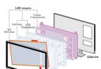
The matrix of a TV consists of free-standing dots of different colors. If you take a magnifying glass and look through it at a switched on monitor, then these points can be easily seen. But on the street screen, the dots are not very densely located, so that they can be distinguished with the naked eye. But from a distance of several tens of meters, these points are indistinguishable.
It turns out that the denser the multi-colored dots are to each other, the less distance the eye needs to mix these colors. Hence the conclusion: unlike three free-standing LEDs, the color mixing of an RGB LED is noticeable already at a distance of 30-70 cm. By the way, an RGB LED with a matte lens shows itself even better.
2. Connecting RGB LED to Arduino
Since the multicolor LED consists of three regular LEDs, we will connect them separately. Each LED is connected to its own pin and has its own separate resistor.
In this tutorial we are using a common cathode RGB LED, so there will only be one wire to ground.
Schematic diagram

Layout appearance
3. Program for controlling RGB-LED
Let's create a simple program that will light each of the three colors in turn.
Const byte rPin = 3; const byte gPin = 5; const byte bPin = 6; void setup () (pinMode (rPin, OUTPUT); pinMode (gPin, OUTPUT); pinMode (bPin, OUTPUT);) void loop () (// turn off blue, turn on red digitalWrite (bPin, LOW); digitalWrite (rPin, HIGH); delay (500); // turn off red, turn on green digitalWrite (rPin, LOW); digitalWrite (gPin, HIGH); delay (500); // turn off green, turn on blue digitalWrite (gPin, LOW); digitalWrite ( bPin, HIGH); delay (500);)
We load the program on Arduino and observe the result.
Let's optimize the program a little: instead of the variables rPin, gPin and bPin, we will use an array. This will help us in the next tasks.
Const byte rgbPins = (3,5,6); void setup () (for (byte i = 0; i<3; i++) pinMode(rgbPins[i], OUTPUT); } void loop() { digitalWrite(rgbPins, LOW); digitalWrite(rgbPins, HIGH); delay(500); digitalWrite(rgbPins, LOW); digitalWrite(rgbPins, HIGH); delay(500); digitalWrite(rgbPins, LOW); digitalWrite(rgbPins, HIGH); delay(500); }
4. Seven colors of the rainbow
Now let's try to light two colors at the same time. Let's program the following color sequence:
- Red
- red + green = yellow
- green
- green + blue = cyan
- blue
- blue + red = purple
For simplicity, we omitted the orange color. So it turned out six colors of the rainbow ????
Const byte rgbPins = (3,5,6); const byte rainbow = ((1,0,0), // red (1,1,0), // yellow (0,1,0), // green (0,1,1), // blue ( 0,0,1), // blue (1,0,1), // purple); void setup () (for (byte i = 0; i<3; i++) pinMode(rgbPins[i], OUTPUT); } void loop() { // перебираем все шесть цветов for(int i=0; i<6; i++){ // перебираем три компоненты каждого из шести цветов for(int k=0; k<3; k++){ digitalWrite(rgbPins[k], rainbow[i][k]); } delay(1000); } }
As a result of the program's work, it turns out:
Your browser does not support the video tag.
5. Smooth color change
It was not for nothing that we connected an RGB LED to pins 3, 5 and 6. As you know, these pins allow you to generate a PWM signal of different duty cycle. In other words, we can not just turn on or off the LED, but control the voltage level across it. This is done using the function analogWrite.
Let's make it so that our LED will transition between the colors of the rainbow, not abruptly, but smoothly.
Const byte rgbPins = (3,5,6); int dim = 1; void setup () (for (byte i = 0; i<3; i++){ pinMode(rgbPins[i], OUTPUT); } // начальное состояние - горит красный цвет analogWrite(rgbPins, 255); analogWrite(rgbPins, 0); analogWrite(rgbPins, 0); } void loop() { // гасим красный, параллельно разжигаем зеленый for(int i=255; i>= 0; i -) (analogWrite (rgbPins, i / dim); analogWrite (rgbPins, (255-i) / dim); delay (10);) // turn off green, turn on blue in parallel for (int i = 255; i> = 0; i -) (analogWrite (rgbPins, i / dim); analogWrite (rgbPins, (255-i) / dim); delay (10);) // extinguish blue, simultaneously light up red for (int i = 255 ; i> = 0; i -) (analogWrite (rgbPins, i / dim); analogWrite (rgbPins, (255-i) / dim); delay (10);))
The dim variable determines the brightness of the glow. With dim = 1, we have the maximum brightness.
We load the program to Arduino.
Your browser does not support the video tag.
Tasks
- Temperature indicator. Let's add a thermistor to the circuit and connect it to the analog input. The LED should change color depending on the temperature of the thermistor. The lower the temperature, the more blue the color, and the higher, the more red.
- RGB lamp with a regulator. Let's add three variable resistors to the circuit and connect them to the analog inputs. The program should continuously read the resistor values and change the color of the corresponding RGB LED component.


