V. V. Getman, N. V. Lezhneva METHODS FOR RECYCLING HEAT OF EXHAUST GASES FROM POWER INSTALLATIONS
Key words: gas turbine plants, combined cycle gas plants
The work considers various methods recovery of heat from flue gases power plants in order to increase their efficiency, save fossil fuels and increase energy capacity.
Keywords: gas-turbine installations, steam-gas installations
In work various methods of utilization of warmth of leaving gases from power installations for the purpose of increasing of their efficiency, economy of organic fuel and accumulation of power capacities are considered.
With the beginning of economic and political reforms in Russia, it is first necessary to make a number of fundamental changes in the country's electric power industry. The new energy policy must solve a number of problems, including the development of modern highly efficient technologies for the production of electrical and thermal energy.
One of these tasks is to increase the efficiency of power plants in order to save fossil fuels and increase energy capacity. Most
Promising in this regard are gas turbine units, the flue gases of which emit up to 20% of the heat.
There are several ways to increase the efficiency of gas turbine engines, including:
Increasing the gas temperature in front of the turbine for a gas turbine unit of a simple thermodynamic cycle,
Application of heat recovery,
Use of flue gas heat in binary cycles,
Creation of a gas turbine unit using a complex thermodynamic scheme, etc.
The most promising direction is considered to be the joint use of gas turbine and steam turbine units (GTU and STU) in order to improve their economic and environmental characteristics.
Gas turbines and combined installations created using them, with currently technically achievable parameters, provide a significant increase in the efficiency of heat and electricity production.
Wide Application binary CCGT units, as well as various combined schemes during the technical re-equipment of thermal power plants will allow saving up to 20% of fuel compared to traditional steam turbine units.
According to experts, the efficiency of the combined steam-gas cycle increases with an increase in the initial temperature of the gases in front of the gas turbine plant and an increase in the share of gas turbine power. Of no small importance
There is also the fact that in addition to the gain in efficiency, such systems require significantly lower capital costs, their specific cost is 1.5 - 2 times less than the cost of gas-fuel oil steam turbine units and CCGT units with minimal gas turbine power.
Based on the data, three main areas for the use of gas turbine units and combined cycle gas turbine units in the energy sector can be identified.
The first, widely used in industrial developed countries, - the use of CCGT units at large condensing thermal power plants operating on gas. In this case, it is most effective to use a recovery-type CCGT unit with a large share of gas turbine power (Fig. 1).
The use of CCGT makes it possible to increase the efficiency of fuel combustion at thermal power plants by ~ 11-15% (CCP with gas discharge into the boiler), by ~ 25-30% (binary CCGT).
Until recently, extensive work on the implementation of CCGT systems in Russia was not carried out. However, single samples of such installations have been in use for quite a long time and have been successfully used, for example, CCGT units with a high-pressure steam generator (HSG) type VPG-50 of the main power unit PGU-120 and 3 modernized power units with HPG-120 at the TPP-2 branch of OJSC TGK-1"; PGU-200 (150) with VPG-450 at the Nevinnomyssk State District Power Plant branch. Three combined-cycle power units with a capacity of 450 MW each are installed at the Krasnodar State District Power Plant. The power unit includes two gas turbines with a capacity of 150 MW, two waste heat boilers and a steam turbine with a capacity of 170 MW, the efficiency of such an installation is 52.5%. Further
increasing the efficiency of utilization-type CCGT units is possible by improving
gas turbine installation and complication of the steam process circuit.
Rice. 1 - Scheme of a CCGT unit with a waste heat boiler
Combined-cycle plant with boiler -
recycler (Fig. 1) includes: 1-
compressor; 2 - combustion chamber; 3 - gas
turbine; 4 - electric generator; 5 - boiler-
recycler; 6 - steam turbine; 7 - capacitor; 8
Pump and 9 - deaerator. The fuel is not burned in the waste heat boiler, and the superheated steam produced is used in a steam turbine unit.
The second direction is the use of gas turbines to create CCGT-CHP and GTU-CHP. Numerous options have been proposed in recent years technological schemes CCGT-CHP. At CHPPs operating on gas, it is advisable to use cogeneration CCGT units
recycling type. A typical example
A large CCGT-CHP of this type is the North-West CHPP in St. Petersburg. One CCGT unit at this thermal power plant includes: two gas turbines with a capacity of 150 MW each, two waste heat boilers, and a steam turbine. Key block indicators: electric power- 450 MW, thermal power - 407 MW, specific consumption standard fuel for electricity supply - 154.5 g. t./(kW.h), specific consumption of equivalent fuel for heat supply - 40.6 kg. t./GJ, efficiency of the thermal power plant for the supply of electrical energy - 79.6%, thermal energy - 84.1%.
The third direction is the use of gas turbines to create CCGT-CHP and GTU-CHP of low and medium power based on boiler houses. CCGT - CHPP and GTU - CHPP of the best options, created on the basis of boiler houses, provide efficiency for the supply of electrical energy in cogeneration mode at the level of 76 - 79%.
A typical combined cycle plant consists of two gas turbine units, each with its own waste heat boiler, which supplies the generated steam to one common steam turbine.
An installation of this type was developed for the Shchekinskaya State District Power Plant. PGU-490 was designed to generate electrical energy in the basic and partial operating modes of the power plant with heat supply to third-party consumers of up to 90 MW under a winter temperature schedule. Schematic diagram unit PGU-490 was forced to focus on the lack of space when placing the waste heat boiler and
steam turbine installation in the power plant buildings, which created certain difficulties in achieving optimal conditions for the combined production of heat and electricity.
In the absence of restrictions on the placement of the installation, as well as when using an improved gas turbine unit, the efficiency of the unit can be significantly increased. As such an improved CCGT, a single-shaft CCGT-320 with a capacity of 300 MW is proposed. The complete gas turbine unit for PGU-320 is the single-shaft GTE-200, the creation of which is expected to be carried out by transition to
double-support rotor, modernization of the cooling system and other components of the gas turbine plant in order to increase the initial gas temperature. In addition to the GTE-200, the PGU-320 monoblock contains a K-120-13 steam turbine with a three-cylinder turbine, a condensate pump, a seal steam condenser, a heater fed by heating steam supplied from the extraction before the last stage of the steam turbine, as well as a two-pressure waste heat boiler containing eight heat exchange areas, including an intermediate steam superheater.
To assess the efficiency of the installation, a thermodynamic calculation was carried out, as a result of which it was concluded that when operating in the condensing mode of the PGU-490 ShchGRES, its electrical efficiency can be increased by 2.5% and brought to 50.1%.
District heating research
combined-cycle plants have shown that the economic indicators of combined cycle gas plants significantly depend on the structure of their thermal circuit, the choice of which is made in favor of an installation that ensures the minimum temperature of the flue gases. This is explained by the fact that flue gases are the main source of energy loss, and to increase the efficiency of the circuit, their temperature must be reduced.
The model of a single-circuit heating CCGT unit, shown in Fig. 2, includes a drum-type waste heat boiler with natural circulation environment in the evaporation circuit. Along the flow of gases in the boiler, heating surfaces are located sequentially from bottom to top:
superheater PP, evaporator I, economizer E and gas superheater for network water GSP.
Rice. 2 - Thermal diagram of a single-circuit CCGT
Calculations of the system showed that when the parameters of fresh steam change, the power generated by the CCGT unit is redistributed between thermal and electrical loads. As steam parameters increase, the generation of electrical energy increases and the generation of thermal energy decreases. This is explained by the fact that as the parameters of fresh steam increase, its production decreases. At the same time, due to a decrease in steam consumption with a small change in its parameters in the extractions, the thermal load of the network water heater is reduced.
A double-circuit CCGT unit, like a single-circuit one, consists of two gas turbines, two waste heat boilers and one steam turbine (Fig. 3). Heating of network water is carried out in two ASG heaters and (if necessary) in a peak network heater.
Along the flow of gases in the waste heat boiler
the following are located sequentially
heating surfaces: superheater high pressure HPHP, HPHP high pressure evaporator, HPHP high pressure economizer, steam superheater low pressure PPND,
low pressure evaporator IND, low pressure gas heater GPND, gas heater for network water GSP.
Rice. 3 - Principal thermal diagram
double-circuit CCGT
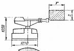
Rice. 4 - Scheme of heat recovery from gas turbine exhaust gases
In addition to the waste heat boiler, the thermal circuit includes a steam turbine with three cylinders, two network water heaters PSG1 and PSG2, a deaerator D and feed pumps PEN. The exhaust steam from the turbine was sent to PSG1. Steam from the turbine exhaust is supplied to the PSG2 heater. All network water passes through PSG1, then part of the water is sent to PSG2, and the other part after the first heating stage is sent to the GSP, located at the end of the gas path of the waste heat boiler. The condensate of the heating steam PSG2 is drained into PSG1, and then enters the HPPG and then into the deaerator. The feed water after the deaerator partially flows into the economizer of the high-pressure circuit, and partially into drum B of the low-pressure circuit. Steam from the low pressure circuit superheater is mixed with the main steam flow after the high pressure cylinder (HPC) of the turbine.
As a comparative analysis has shown, when using gas as the main fuel, the use of utilization schemes is advisable if the ratio of thermal and electrical energy is 0.5 - 1.0, with ratios of 1.5 or more, preference is given to CCGT units using a “discharge” scheme.
In addition to adjusting the steam turbine cycle to the gas turbine cycle, recycling the heat of exhaust gases
GTU can be implemented by supplying steam generated by a waste heat boiler to the combustion chamber of the GTU, as well as by implementing a regenerative cycle.
The implementation of the regenerative cycle (Fig. 4) provides a significant increase in the efficiency of the installation, by 1.33 times, if, when creating a gas turbine unit, the degree of pressure increase is selected in accordance with the intended degree of regeneration. This circuit includes a K-compressor; R - regenerator; KS - combustion chamber; ТК - compressor turbine; ST - power turbine; CC - centrifugal compressor. If a gas turbine unit is designed without regeneration, and the degree of pressure increase l is close to the optimal value, then equipping such a gas turbine unit with a regenerator does not lead to an increase in its efficiency.
The efficiency of the installation that supplies steam to the combustion chamber is increased by 1.18 times compared to a gas turbine unit, which makes it possible to reduce the consumption of fuel gas consumed by the gas turbine unit.
A comparative analysis showed that the greatest fuel savings are possible when implementing the regenerative cycle of a gas turbine unit with a high degree of regeneration, a relatively low pressure ratio in the compressor l = 3 and with small losses of combustion products. However, in most domestic TKAs, aviation and marine gas turbine engines with a high degree of pressure increase are used as a drive, and in this case, heat recovery from exhaust gases is more efficient in a steam turbine unit. Installation with steam supply to the combustion chamber is structurally the simplest, but less effective.
One of the ways to achieve gas savings and solutions environmental problems is the use of combined cycle gas plants at compressor stations. Research studies consider two alternative options use of steam obtained from the recovery of heat from the exhaust gases of a gas turbine unit: a combined cycle gas turbine unit driven by a supercharger steam turbine natural gas and from the steam turbine of an electric generator. The fundamental difference between these options is that in the case of a CCGT with a supercharger, not only the heat of the exhaust gases of the GPU is recovered, but also one GPU is replaced by a steam turbine pumping unit, and in the case of a CCGT with an electric generator, the number of GPUs is maintained, and due to the recovered heat, electricity is generated by a special steam turbine unit. The analysis showed that CCGT units with a natural gas supercharger drive provided the best technical and economic indicators.
In the case of creating a combined cycle gas plant with a waste heat boiler on the basis of a compressor station, the gas turbine unit is used to drive the supercharger, and the steam power plant (SPU) is used to generate electricity, while the temperature of the exhaust gases behind the waste heat boiler is 1400C.
In order to increase the efficiency of using fossil fuels in decentralized systems heat supply, it is possible to reconstruct heating boiler houses with the placement of small-capacity gas turbine units (GTUs) in them and the disposal of combustion products in the furnaces of existing boilers. At the same time, the electrical power of the gas turbine depends on the operating modes according to thermal or electrical load schedules, as well as on economic factors.
The effectiveness of boiler house reconstruction can be assessed by comparing two options: 1 - original (existing boiler house), 2 - alternative, using a gas turbine unit. The greatest effect was obtained with an electric power of the gas turbine equal to
maximum load consumption area.
Comparative analysis of a gas turbine unit with a HRSG producing steam in the amount of 0.144 kg/kg s. g., condensing TU and GTU without HRSG and with TU of dry heat exchange showed the following: useful
electric power - 1.29, natural gas consumption - 1.27, heat supply - 1.29 (12650 and 9780 kJ/m3 of natural gas, respectively). Thus, the relative increase in gas turbine power when introducing steam from the HRSG was 29%, and the consumption of additional natural gas was 27%.
According to operational test data, the temperature of flue gases in hot water boilers is 180 - 2300C, which creates favorable conditions for recycling the heat of gases using condensing heat exchangers (TU). In TU, which
are used to preheat network water before hot water boilers, heat exchange takes place with the condensation of water vapor contained in the flue gases, and the heating of the water in the boiler itself occurs in the “dry” heat exchange mode.
According to the data, along with fuel savings, the use of technical specifications also provides energy savings. This is explained by the fact that when an additional flow of circulating water is introduced into the boiler, in order to maintain the calculated flow rate through the boiler, it is necessary to transfer part of the return water of the heating network in an amount equal to the recirculation flow rate from return pipe to the server.
When completing power plants from separate power units with a gas turbine drive
electric generators, there are several options for recycling the heat of exhaust gases, for example, using a recovery
heat exchanger (HTE) for heating water, or using a waste heat boiler and
steam turbine generator to increase electricity generation. An analysis of the station's operation taking into account heat recovery using heat treatment showed a significant increase in the heat utilization coefficient, in some cases by 2 times or more, and experimental studies of the EM-25/11 power unit with the NK-37 engine allowed us to draw the following conclusion. Depending on specific conditions, the annual supply of recovered heat can range from 210 to 480 thousand GJ, and real savings gas amounted from 7 to 17 thousand m3.
Literature
1. V.M. Maslennikov, Thermal Power Engineering, 3, 39-41 (2000).
2. V.I. Romanov, V.A. Krivutsa, Thermal Energy, 4, 27-30 (1996).
3. L.V. Arsenyev, V.G. Tyryshkin, Combined installations with gas turbines. L.: Mechanical Engineering, 1982, 407 p.
4. V.I. Dlugoselsky, A.S. Zemtsov, Thermal Power Engineering, 12, 3-7 (2000).
5. B.M. Troyanovsky, A.D. Trukhniy, V.G. Gribin, Thermal Power Engineering, 8, 9-13 (1998).
6. A. D. Tsoi, Industrial Energy, 4, 50-52 (2000).
7. A.D. Tsoi, A.V. Klevtsov, A.V. Koryagin, Industrial Energy, 12, 25-32 (1997).
8. V.I. Eveneno, Thermal Energy, 12, 48-50 (1998).
9. N.I. Serebryannikov, E.I. Tapelev, A.K. Makhankov, Energy saving and water treatment, 2, 3-11 (1998).
10. G.D. Barinberg, V.I. Dlugoselsky, Teploenergetika, 1, 16-20 (1998)
11. A.P. Bersenev, Teploenergetika, 5, 51-53 (1998).
12. E.N. Bukharkin, Industrial Energy, 7, 34-37 (1998).
13. V.I. Dobrokhotov, Thermal Power Engineering, 1, 2-8 (2000).
14. A.S. Popov, E.E. Novgorodsky, B.A. Permyakov, Industrial Energy, 1, 34-35 (1997).
15. I.V. Belousenko, Industrial Energy, 5, 53-55 (2000).
16. V.V. Getman, N.V. Lezhneva, Vestnik Kazan. technol. Univ., 18, 174-179 (2011).
17. N.V. Lezhneva, V.I. Elizarov, V.V. Getman, Vestnik Kazan. technol. Univ., 17, 162-167 (2012).
© V.V. Getman - Ph.D. tech. Sciences, Associate Professor department automation technological processes and production facilities of the Federal State Budgetary Educational Institution of Higher Professional Education "KNRTU", 1ega151@uaMech; N.V. Lezhneva - Ph.D. tech. Sciences, Associate Professor department automation of technological processes and production of FSBEI HPE "KNRTU", [email protected].
Currently the temperature is leaving flue gases for the boiler, a temperature of at least 120-130°C is taken for two reasons: to avoid condensation of water vapor on hogs, flues and chimneys and to increase natural traction, reducing the pressure of the smoke exhauster. In this case, the heat of exhaust gases and the latent heat of vaporization of water vapor can be usefully used. The use of the heat of exhaust flue gases and the latent heat of vaporization of water vapor is called the method of deep utilization of the heat of flue gases. Currently, there are various technologies for implementing this method, tested in Russian Federation and have found widespread use abroad. The method of deep utilization of heat from flue gases makes it possible to increase the efficiency of a fuel-consuming installation by 2-3%, which corresponds to a reduction in fuel consumption by 4-5 kg of fuel equivalent. per 1 Gcal of generated heat. When implementing this method, there are technical difficulties and limitations associated mainly with the complexity of calculating the heat and mass transfer process during deep heat recovery of exhaust flue gases and the need to automate the process, however, these difficulties can be solved with the current level of technology.
For the widespread implementation of this method, it is necessary to develop guidelines for the calculation and installation of systems for deep heat recovery of flue gases and the adoption of legal acts prohibiting the commissioning of fuel-using installations on natural gas without the use of deep recovery of flue gas heat.
1. Formulation of the problem regarding the method (technology) under consideration for increasing energy efficiency; forecast of excessive consumption of energy resources, or description of other possible consequences on a national scale if the current situation is maintained
Currently, the temperature of the exhaust flue gases behind the boiler is taken to be no lower than 120-130 ° C for two reasons: to prevent condensation of water vapor on hogs, flues and chimneys and to increase natural draft, which reduces the pressure of the smoke exhauster. In this case, the temperature of the flue gases directly affects the value of q2 - heat loss with flue gases, one of the main components heat balance boiler For example, reducing the temperature of flue gases by 40°C when the boiler is operating on natural gas and an excess air ratio of 1.2 increases the gross efficiency of the boiler by 1.9%. This does not take into account the latent heat of vaporization of combustion products. Today, the vast majority of water heating and steam boiler units in our country that burn natural gas are not equipped with installations that use the latent heat of steam formation of water vapor. This heat is lost along with the exhaust gases.
2. Availability of methods, methods, technologies, etc. to solve the identified problem
Currently, methods of deep heat recovery from flue gases (WER) are used through the use of recuperative, mixing, and combined devices that operate using various methods of using the heat contained in the flue gases. At the same time, these technologies are used in the majority of boilers commissioned abroad that burn natural gas and biomass.
3. Short description the proposed method, its novelty and awareness of it, the availability of development programs; result with mass implementation nationwide
The most commonly used method of deep heat recovery from flue gases is that the combustion products of natural gas after a boiler (or after a water economizer) with a temperature of 130-150°C are divided into two streams. Approximately 70-80% of the gases are directed through the main gas duct and enter the surface-type condensing heat exchanger, the rest of the gases are sent to the bypass gas duct. In the heat exchanger, the combustion products are cooled to 40-50°C, and some of the water vapor condenses, which makes it possible to usefully use both the physical heat of the flue gases and the latent heat of condensation of some of the water vapor contained in them. The cooled combustion products after the droplet separator are mixed with the uncooled combustion products passing through the bypass flue and, at a temperature of 65-70°C, are removed by a smoke exhauster through chimney in atmosphere. The heated medium in the heat exchanger can be source water for the needs of chemical water treatment or air, which is then supplied for combustion. To intensify heat exchange in the heat exchanger, it is possible to supply vapor from the atmospheric deaerator into the main gas duct. It is also necessary to note the possibility of using condensed desalted water vapor as source water. The result of the implementation of this method is an increase in the gross efficiency of the boiler by 2-3%, taking into account the use of the latent heat of steam formation of water vapor.
4. Forecast of the effectiveness of the method in the future, taking into account:
- rising energy prices;
- growth in the well-being of the population;
- introduction of new environmental requirements;
- other factors.
This method increases the efficiency of natural gas combustion and reduces emissions of nitrogen oxides into the atmosphere due to their dissolution in condensing water vapor.
5. List of groups of subscribers and objects where this technology can be used c maximum efficiency; the need for additional research to expand the list
This method can be used in steam and hot water boiler houses using natural and liquefied gas and biofuel as fuel. To expand the list of objects where this method can be used, it is necessary to conduct research on the processes of heat and mass transfer of combustion products of fuel oil, light diesel fuel and various brands coals.
6. Identify the reasons why the proposed energy-efficient technologies are not applied on a mass scale; outline an action plan to remove existing barriers
Mass application of this method in the Russian Federation is not carried out, as a rule, for three reasons:
- Lack of awareness about the method;
- The presence of technical limitations and difficulties in implementing the method;
- Lack of funding.
7. The presence of technical and other restrictions on the use of the method at various sites; in the absence of information on possible limitations, they must be determined by testing
Technical limitations and difficulties in implementing the method include:
- The complexity of calculating the process of recycling wet gases, since the heat exchange process is accompanied by mass transfer processes;
- The need to maintain specified values of temperature and humidity of exhaust flue gases, in order to avoid condensation of vapors in the flues and chimney;
- The need to avoid freezing of heat exchange surfaces when heating cold gases;
- In this case, it is necessary to test flues and chimneys treated with modern anti-corrosion coatings to determine the possibility of reducing restrictions on the temperature and humidity of the flue gases leaving the heat recovery unit.
8. The need for R&D and additional testing; topics and goals of work
The need for R&D and additional testing is given in paragraphs 5 and 7.
9. Existing measures encouragement, coercion, stimulation for the implementation of the proposed method and the need for their improvement
There are no existing measures to encourage and enforce the implementation of this method. The introduction of this method may be stimulated by interest in reducing fuel consumption and emissions of nitrogen oxides into the atmosphere.
10. The need to develop new or amend existing laws and regulations
It is necessary to develop guidelines for the calculation and installation of systems for deep heat recovery of flue gases. It may be necessary to adopt legal acts prohibiting the commissioning of natural gas fuel-using plants without the use of deep recovery of flue gas heat.
11. Availability of regulations, rules, instructions, standards, requirements, prohibitive measures and other documents regulating the use of this method and mandatory for execution; the need to make changes to them or the need to change the very principles of the formation of these documents; the presence of pre-existing normative documents, regulations and the need for their restoration
There are no questions regarding the application of this method in the existing regulatory framework.
12. Availability of implemented pilot projects, analysis of their actual effectiveness, identified shortcomings and proposals for improving the technology, taking into account accumulated experience
There is no data on the large-scale implementation of this method in the Russian Federation; there is experience of implementation at the thermal power plants of RAO UES and, as mentioned above, extensive experience has been accumulated in deep utilization of flue gases abroad. The All-Russian Thermal Engineering Institute has completed design studies of installations for deep heat recovery of combustion products for PTVM (KVGM) hot water boilers. The disadvantages of this method and suggestions for improvement are given in paragraph 7.
13. Possibility of influencing other processes with the mass introduction of this technology (changes in the environmental situation, possible impact on human health, increased reliability of energy supply, changes in daily or seasonal loading schedules of energy equipment, changes in economic indicators of energy production and transmission, etc.)
Mass implementation of this method will reduce fuel consumption by 4-5 kg of fuel equivalent. per Gcal of generated heat and will affect the environmental situation by reducing emissions of nitrogen oxides.
14. Availability and sufficiency of production capacity in Russia and other countries for the mass introduction of the method
Profile production capacity in the Russian Federation is able to ensure the implementation of this method, but not in a monoblock design; when using foreign technologies, a monoblock design is possible.
15. The need for special training of qualified personnel to operate the technology being introduced and develop production
To implement this method, existing specialized training of specialists is required. It is possible to organize specialized seminars on the implementation of this method.
16. Proposed methods of implementation:
1) commercial financing (with cost recovery);
2) competition for the implementation of investment projects developed as a result of work on energy planning for the development of a region, city, settlement;
3) budget financing for effective energy-saving projects with long payback periods;
4) introduction of prohibitions and mandatory requirements for use, supervision of their compliance;
5) other offers.
Suggested implementation methods are:
- budget financing;
- attracting investments (payback period 5-7 years);
- introduction of requirements for the commissioning of new fuel-consuming installations.
In order to add a description of energy-saving technology to the Catalog, fill out the questionnaire and send it to marked “to Catalog”.
Use: energy, waste heat recovery. The essence of the invention: the gas flow is moistened by passing it through a condensate film formed on a dihedral perforated sheet 4, where the gases are saturated with water vapor. In chamber 2 above sheet 4, volumetric condensation of water vapor occurs on dust particles and tiny droplets of vapor-gas flow. The prepared vapor-gas mixture is cooled to the dew point temperature by transferring the heat of the flow of the heated medium through the wall of the heat exchange elements 8. Condensate from the flow falls onto inclined partitions 5 with gutters 10 and then enters sheet 4 through the drain pipe 9. 1 il.
The present invention relates to the field of boiler technology, and more specifically to the field of waste gas heat recovery. There is a known method for recycling the heat of exhaust gases (USSR Aut.St. N 1359556, MKI F 22 V 33/18, 1986), which is the closest analogue, in which the combustion products are sequentially forcibly moistened, compressed in a compressor, cooled to a temperature below the dew point temperature together with condensation of water vapor at a pressure above atmospheric pressure, they are separated in a separator, expanded with a simultaneous decrease in temperature in a turboexpander and removed into the atmosphere. There is a known method for recycling the heat of exhaust gases (GDR, Pat. N 156197, MKI F 28 D 3/00, 1982) achieved by countercurrent movement in a heat exchanger of exhaust gases and an intermediate liquid medium, heated to a temperature greater than the dew point temperature of the exhaust gases, which are cooled to a temperature below the dew point. Known method low temperature heating using the higher calorific value of the fuel (Germany, application N OS 3151418, MKI F 23 J 11/00, 1983), which consists in the fact that fuel is burned in the heating device with the formation of hot gases that enter the heating device forward and to the side. In part of the flow path, fuel gases are directed downward to form condensate. The fuel gases at the outlet have a temperature of 40–45 o C. Known method allows cooling of exhaust gases below the dew point temperature, which slightly increases the thermal efficiency of the installation. However, in this case, condensate is sprayed through the nozzles, which leads to additional energy consumption for its own needs and increases the content of water vapor in the combustion products. The inclusion of a compressor and a turboexpander in the circuit, which, respectively, compress and expand the combustion products, does not increase efficiency, and, in addition, leads to additional energy consumption associated with losses in the compressor and turboexpander. The objective of the invention is to intensify heat exchange with deep utilization of heat from exhaust gases. The problem is solved due to the fact that the gas flow is humidified by passing it through a film of condensate with saturation of the flow with water vapor, followed by condensation of the latter, as well as the condensate falling onto the said film and draining the unevaporated part. The proposed method can be implemented in the device shown in the drawing, where: 1 condensate collector, 2 chamber, 3 housing, 4 dihedral unequal inclined perforated sheet, 5 inclined partitions, 6 tapering two-dimensional diffuser, 7 expanding diffuser, 8 heat exchange surface, 9 drain pipe, 10 gutter, 11 mating surface, 12 - separator, 13 overheating heat exchanger, 14 smoke exhauster, 15 chimney, 16 water seal, 17 horizontal axis. The operation of the device according to the proposed method of utilizing the heat of combustion products is similar to an atmospheric heat pipe. Its evaporative part is located in the lower part of chamber 2, from which the prepared vapor-gas mixture rises, and the condensation part on the heat exchange surfaces 3, from which condensate flows along inclined partitions 5 with gutters 10 through drain pipes 9 onto a dihedral unequal-sided perforated sheet 4, and the excess into condensate collector 1. Combustion products coming from the superheat heat exchanger 13 bubble a film of condensate on a dihedral unequally inclined perforated sheet 4. The condensate is sprayed, heated and evaporated, and its excess flows into the condensate collector 1. Flue gases are saturated with water vapor at a pressure approximately equal to atmospheric. It depends on the mode collaboration fan and smoke exhauster 14. In chamber 2, water vapor is in a supersaturated state, since the vapor pressure in the gas mixture is greater than the saturated vapor pressure. The smallest droplets, dust particles of combustion products become condensation centers, on which the process of volumetric condensation of water vapor occurs in chamber 2 without heat exchange with the environment. The prepared vapor-gas mixture condenses on the heat exchange surfaces 8. At the surface temperature of these heat exchange elements 8 significantly below the dew point temperature, the moisture content of the combustion products after the heat recovery device is lower than the initial one. The final phase of this continuous process is the precipitation of condensate on the inclined partitions 5 with complaints 10 and its entry onto the perforated sheet 4 through the drain pipe 9. The achievement of the task is confirmed by the following: 1. The value of the heat transfer coefficient increased to 180-250 W/m 2 o C, which sharply reduces the heat transfer surface area and, accordingly, reduces the weight and size indicators. 2. A 2.5 to 3 times reduction in the initial moisture content of water vapor in the flue gases reduces the intensity of corrosion processes in the gas path and chimney. 3. Fluctuations in the steam generator load do not reduce the efficiency of the boiler plant.
Claim
A method of utilizing the heat of exhaust gases, which consists in the fact that the gas flow is humidified and cooled to the dew point temperature by transferring the heat of the flow to the heated medium through the wall, characterized in that the gas flow is humidified by passing it through a condensate film with saturation of the flow with water vapor, followed by condensation of the latter, as well as the precipitation of condensate on the mentioned film and the drainage of its unevaporated part.
Owners of patent RU 2606296:
The invention relates to thermal power engineering and can be used at any enterprise that operates boilers using hydrocarbon fuels.
Known commercially produced by the Kostroma Heating Plant are heaters of the KSk type (Kudinov A.A. Energy saving in heat-generating installations. - Ulyanovsk: UlSTU, 2000. - 139, p. 33), consisting of a gas-water surface heat exchanger, the heat exchange surface of which is made of finned bimetallic tubes, strainer, distribution valve, drip eliminator and hydropneumatic blower.
Heaters of the KSk type work as follows. Flue gases enter the distribution valve, which divides them into two streams, the main gas flow is directed through a mesh filter into the heat exchanger, the second through the bypass line of the flue. In the heat exchanger, water vapor contained in the flue gases condenses on finned tubes, heating the water flowing in them. The resulting condensate is collected in a pan and pumped into the heating network feed circuit. The water heated in the heat exchanger is supplied to the consumer. At the outlet of the heat recovery unit, the dried flue gases are mixed with the original flue gases from the flue bypass line and sent through a smoke exhauster into the chimney.
For the heat exchanger to operate in the condensation mode of its entire convective part, it is required that the heating temperature of the water in the convective package does not exceed 50°C. To use such water in heating systems, it must be additionally heated.
To prevent condensation of residual water vapor from flue gases in the flues and chimney, part of the source gases is mixed into the dried flue gases through a bypass channel, increasing their temperature. With such an admixture, the content of water vapor in the exhaust flue gases also increases, reducing the efficiency of heat recovery.
A heat exchanger is known (RU 2323384 C1, IPC F22B 1/18 (2006.01), published on April 27, 2008), containing a contact heat exchanger, a droplet eliminator, a gas-gas heat exchanger connected according to a direct flow circuit, gas ducts, pipelines, a pump, temperature sensors, valves - regulators. Along the flow of circulating water of the contact heat exchanger, a water-to-water heat exchanger and a water-to-air heat exchanger with a bypass channel along the air flow are located in series.
A known method of operation of this heat exchanger. The exhaust gases through the gas duct enter the inlet of the gas-gas heat exchanger, sequentially passing through its three sections, then to the inlet of the contact heat exchanger, where, passing through a nozzle washed by circulating water, they are cooled below the dew point, giving off sensible and latent heat to the circulating water. Next, the cooled and moist gases are freed from most of the liquid water carried away in a droplet eliminator, heated and dried in at least one section of the gas-gas heat exchanger, sent into a chimney by a smoke exhauster and released into the atmosphere. At the same time, heated circulating water from the sump of the contact heat exchanger is pumped into the water-water heat exchanger, where it heats cold water from the pipeline. The water heated in the heat exchanger is supplied to the needs of process and domestic hot water supply or to a low-temperature heating circuit.
Next, the recycled water enters the water-air heat exchanger, heats at least part of the blown air coming from outside the room through the air duct, cooling to the minimum possible temperature, and enters the contact heat exchanger through the water distributor, where it takes heat from the gases, simultaneously washing them from suspended particles, and absorbs some of the oxides of nitrogen and sulfur. The heated air from the heat exchanger is supplied by a blower fan to a standard air heater or directly to the firebox. Recycled water is filtered if necessary and processed by known methods.
To implement this method, a control system is required due to the use of recovered heat for hot water supply purposes due to the variability of the daily schedule of hot water consumption.
Water heated in the heat exchanger, supplied for the needs of hot water supply or in a low-temperature heating circuit, requires it to be brought to the required temperature, since it cannot be heated in the heat exchanger above the temperature of the return circuit water, which is determined by the saturation temperature of water vapor in the flue gases. The low heating of the air in the water-to-air heat exchanger does not allow this air to be used for space heating.
The closest to the claimed invention are a device and method for utilizing heat from flue gases (RU 2436011 C1, IPC F22B 1/18 (2006.01), published 12/10/2011).
The flue gas heat recovery device contains a gas-gas surface plate heat exchanger made according to a counterflow circuit, a surface gas-air plate condenser, an inertial drop catcher, gas ducts, a smoke exhauster, air ducts, fans and a pipeline.
The feed flue gases are cooled in a gas-to-gas surface plate heat exchanger, heating the dried flue gases. The heating and heated medium move in countercurrent. In this case, the wet flue gases are deeply cooled to a temperature close to the dew point of water vapor. Next, the water vapor contained in the flue gases is condensed in a gas-air surface plate heat exchanger - a condenser, heating the air. The heated air is used to heat the premises and cover the needs of the combustion process. The condensate after additional processing is used to make up for losses in the heating network or steam turbine cycle. To prevent condensation of residual water vapor carried away by the flow from the condenser, a portion of the heated, dried flue gases is mixed in front of the additional smoke exhauster. The dried flue gases are supplied by a smoke exhauster to the heater described above, where they are heated to prevent possible condensation of water vapor in the flues and chimney and are directed into the chimney.
The disadvantages of this method are that predominantly the latent heat of condensation of water vapor contained in the flue gases is utilized. If the recuperative heat exchanger cools the source flue gases to a temperature close to the dew point of water vapor, then the heating of the exhaust dried flue gases will be excessive, which reduces the efficiency of recycling. The disadvantage is the use of only one medium for heating - air.
The objective of the invention is to increase the efficiency of flue gas heat recovery through the use of latent heat of condensation of water vapor and elevated temperature the flue gases themselves.
In the proposed method of deep heat recovery from flue gases, as well as in the prototype, the flue gases are pre-cooled in a gas-gas surface plate heat exchanger, heating the dried flue gases, and the water vapor contained in the flue gases is condensed in the condenser, heating the air.
According to the invention, between the heat exchanger and the condenser, the flue gases are cooled to a temperature close to the dew point of water vapor, heating the water.
Gas boilers have high temperature exhaust flue gases (130°C for large energy boilers, 150°C-170°C for small boilers). To cool flue gases before condensation, two devices are used: a recuperative gas-to-gas heat exchanger and a recovery water heater.
The source flue gases are pre-cooled in a gas-gas surface plate heat exchanger, heating the dried flue gases 30-40°C higher than the saturation temperature of the water vapor contained in them, to create a temperature reserve for possible cooling of the flue gases in the pipe. This allows you to reduce the heat exchange area recuperative heat exchanger compared to the prototype and it is useful to use the remaining heat of the flue gases.
A significant difference is the use of a contact gas-water water heater for the final cooling of wet flue gases to a temperature close to the dew point of water vapor. At the entrance to the water heater, the flue gases have a fairly high temperature (130°C-90°C), which allows water to be heated to 50°C-65°C with partial evaporation. At the exit from a contact gas-water water heater, the flue gases have a temperature close to the dew point of the water vapor they contain, which increases the efficiency of using the heat exchange surface in the condenser, eliminates the formation of dry zones of the condenser and increases the heat transfer coefficient.
The method of utilizing heat from flue gases is shown in Fig.1.
Table 1 shows the results of the verification calculation of the installation option for a natural gas boiler with a capacity of 11 MW.
The method of deep utilization of heat from flue gases is carried out as follows. The source flue gases 1 are pre-cooled in a gas-gas surface plate heat exchanger 2, heating the dried flue gases. Next, the flue gases 3 are finally cooled in a contact gas-water water heater 4 to a temperature close to the dew point of water vapor, spraying water, for which it is advisable to use the condensate obtained in the condenser. In this case, part of the water evaporates, increasing the moisture content of the flue gases, and the rest is heated to the same temperature. The water vapor contained in the flue gases 5 is condensed in a gas-air surface plate heat exchanger - a condenser 6 with a droplet eliminator 7, heating the air. Condensate 8 is supplied for heating to a contact gas-water water heater 4. The heat of condensation is used to heat cold air, which is supplied by fans 9 from environment through air duct 10. Heated air 11 is directed to the production room of the boiler shop for ventilation and heating. From this room, air is supplied to the boiler to ensure the combustion process. The dried flue gases 12 are supplied by a smoke exhauster 13 to a gas-gas surface plate heat exchanger 2 for heating and sent to the chimney 14.
To avoid condensation of residual water vapor carried away by the flow from the condenser, a portion of the heated, dried flue gases 15 (up to 10%) is mixed in front of the smoke exhauster 13 (up to 10%), the value of which is initially adjusted by the damper 16.
The temperature of the heated air 11 is regulated by changing the flow rate of the dried flue gases 1 or by changing the air flow rate by adjusting the speed of the smoke exhauster 13 or fans 9 depending on the outside air temperature.
Heat exchanger 2 and condenser 6 are surface plate heat exchangers made of unified modular packages, which are arranged in such a way that the coolant flows countercurrently. Depending on the volume of flue gases to be dried, the heater and condenser are formed from a calculated number of packages. Water heater 4 is a contact gas-water heat exchanger that provides additional cooling of flue gases and heating of water. Heated water 17 after additional processing is used to replenish losses in the heating network or steam turbine cycle. Block 9 is formed from several fans to change the flow of heated air.
Table 1 shows the results of the verification calculation of the installation option for a natural gas boiler with a capacity of 11 MW. Calculations were carried out for an outside air temperature of -20°C. The calculation shows that the use of a contact gas-water water heater 4 leads to the disappearance of the dry zone in the condenser 6, intensifies heat exchange and increases the power of the installation. The percentage of recovered heat increases from 14.52 to 15.4%, while the dew point temperature of water vapor in the dried flue gases decreases to 17°C. Approximately 2% of the thermal power is not utilized, but is used for recovery - heating the dried flue gases to a temperature of 70°C.
A method of deep utilization of heat from flue gases, according to which the flue gases are pre-cooled in a gas-gas surface plate heat exchanger, heating the dried flue gases, cooled in a water heater to a temperature close to the dew point of water vapor, heating the water, condensing the water vapor contained in the flue gases in the condenser, heating the air, characterized in that a surface tubular gas-water heater is installed between the heat exchanger and the condenser to cool wet flue gases and heat water, while the main heat recovery occurs in the condenser when heating the air, and additional heat recovery occurs in the water heater.
Similar patents:
The invention relates to petrochemical engineering and can be used for cracking fuel oil, as well as for heating process media (for example, oil, oil emulsion, gas, mixtures thereof) and for other technological processes requiring intensive heat supply.
The invention relates to the field of thermal power engineering and can be used in heating and air conditioning systems. The invention lies in the fact that the connection of heat exchange finned tubes in a row and rows to each other is made sequentially, one tube per run in one branch, and adjacent heat exchange tubes in a row are connected to each other in series by inter-tube transitions in the form of steeply bent bends and are equipped with easily removable repair and protective plugs , the number of series-connected tubes in a row and the total number of strokes in all rows are selected depending on the actual parameters of the existing heating network and determined by the hydraulic characteristics of the water heater.
An electric radiator that uses computing processors as a heat source. This radiator is for household and production premises, using computing processors as heat sources, contains a heated housing that carries out heat transfer between the heat source and the surrounding air, the number Q of processors distributed over the number P printed circuit boards, forming the heat source of the radiator and powerful tool, performing calculations using external information systems, a human-machine interface that allows you to control computing and thermal power, issued by the radiator, a stabilized power supply for various electronic components, a network interface that allows you to connect the radiator to external networks.
The invention is intended for implementation of steam reforming reactions and can be used in the chemical industry. The heat exchange reactor contains a plurality of bayonet tubes (4) suspended from the upper roof (2), extending to the level of the lower bottom (3) and enclosed in a casing (1) containing inlet (E) and outlet (S) pipes for flue gases.
The invention provides a system and method for steam-gas conversion. The method of steam-gas cogeneration based on gasification and methanation of biomass includes: 1) gasification of biomass by mixing oxygen and water vapor obtained from an air separation unit with biomass, transporting the resulting mixture through a nozzle to the gasifier, gasification of biomass at a temperature of 1500-1800°C and a pressure of 1-3 MPa with the production of raw gasified gas and transportation of superheated steam having a pressure of 5-6 MPa, obtained as a result of expedient heat recovery, to the steam turbine; 2) conversion and purification: according to the requirements of the methanation reaction, adjust the hydrogen/carbon ratio of the crude gasified gas generated in step 1) to 3:1 using the conversion reaction, and extract at low temperature the crude gasified gas using methanol for desulfurization and decarbonization , resulting in purified syngas; 3) carrying out methanation: introducing the purified syngas of stage 2) into the methanation section, consisting of a primary methanation section and a secondary methanation section, the primary methanation section containing a first primary methanation reactor and a second primary methanation reactor connected in series; allowing a portion of the process gas from the second primary methanation reactor to return to the inlet of the first primary methanation reactor to mix with fresh feed gas and then be able to enter the first primary methanation reactor, so that the concentration of reactants at the inlet of the first primary methanation reactor is reduced and the temperature of the catalyst bed is controlled by the process gas; introduction of syngas after primary methanation into a secondary methanation section containing a first secondary methanation reactor and a second secondary methanation reactor connected in series, where not a large number of unreacted CO and a large amount of CO2 is converted into CH4, and transporting the superheated intermediate pressure steam generated in the methanation section to the steam turbine; and 4) methane concentration: concentration of methane synthetic natural gas containing trace amounts of nitrogen and water vapor obtained in step 3) using pressure swing adsorption, so that the molar concentration of methane reaches 96% and the calorific value of synthetic natural gas reaches 8256 kcal /Nm3.
The invention relates to thermal power engineering. The method of deep heat recovery from flue gases includes pre-cooling of flue gases in a gas-gas surface plate heat exchanger, heating dried flue gases with countercurrent to create a temperature reserve that prevents condensation of residual water vapor in the chimney. Further cooling of the flue gases to a temperature close to the dew point of water vapor is carried out in a contact gas-water water heater, which heats the water. Cooled wet flue gases are fed into a gas-air surface plate heat exchanger - a condenser, where the water vapor contained in the flue gases is condensed, heating the air. The dried flue gases are supplied by an additional smoke exhauster to a gas-gas surface plate heat exchanger, where they are heated to prevent possible condensation of water vapor in the flues and chimney and are directed into the chimney. Technical result: increasing the efficiency of flue gas heat recovery through the use of latent heat of condensation of water vapor and the increased temperature of the flue gases themselves. 1 ill., 1 tab.
Heat recovery from flue gases
Flue gases leaving working space ovens have a very high temperature and therefore carry away a significant amount of heat. In open-hearth furnaces, for example, about 80% of the total heat supplied to the working space is carried away from the working space with flue gases, in heating furnaces about 60%. From the working space of the furnaces, the flue gases carry away more heat with them, the higher their temperature and the lower the heat utilization coefficient in the furnace. In this regard, it is advisable to ensure the recovery of heat from exhaust flue gases, which can be performed in two fundamental ways: with the return of part of the heat taken from the flue gases back to the furnace and without returning this heat to the furnace. To implement the first method, it is necessary to transfer the heat taken from the smoke to gas and air (or only air) going into the furnace. To achieve this goal, heat exchangers of recuperative and regenerative types are widely used, the use of which makes it possible to increase the efficiency of the furnace unit, increase the combustion temperature and save fuel. With the second recovery method, the heat of exhaust flue gases is used in thermal power boiler houses and turbine units, which achieves significant fuel savings.
In some cases, both described methods of waste heat recovery are used simultaneously. This is done when the temperature of the flue gases after regenerative or recuperative heat exchangers remains sufficiently high and further heat recovery in thermal power plants is advisable. For example, in open-hearth furnaces, the temperature of the flue gases after the regenerators is 750-800 °C, so they are reused in waste heat boilers.
Let us consider in more detail the issue of recycling the heat of exhaust flue gases with the return of part of their heat to the furnace.
It should be noted, first of all, that a unit of heat taken from the smoke and introduced into the furnace by air or gas (a unit of physical heat) turns out to be much more valuable than a unit of heat obtained in the furnace as a result of combustion of fuel (a unit of chemical heat), since the heat of the heated air (gas) does not entail heat loss with flue gases. The value of a unit of sensible heat is greater, the lower the fuel utilization factor and the higher the temperature of the exhaust flue gases.
For normal operation of the furnace, it is necessary to supply the working space every hour. required amount heat. This amount of heat includes not only the heat of the fuel, but also the heat of heated air or gas, i.e.
It is clear that with = const an increase will reduce . In other words, utilization of heat from flue gases makes it possible to achieve fuel savings, which depends on the degree of heat recovery from flue gases
where is the enthalpy of heated air and flue gases escaping from the working space, kW, or kJ/period, respectively.
The degree of heat recovery can also be called efficiency. recuperator (regenerator), %
Knowing the degree of heat recovery, you can determine fuel economy using the following expression:
![]()
where I"d, Id are, respectively, the enthalpy of the flue gases at the combustion temperature and those leaving the furnace.
Reducing fuel consumption as a result of using the heat of exhaust flue gases usually provides a significant economic effect and is one of the ways to reduce the cost of heating metal in industrial furnaces.
In addition to saving fuel, the use of air (gas) heating is accompanied by an increase in calorimetric combustion temperature, which may be the main purpose of recovery when heating furnaces with fuel with a low calorific value.
An increase in at leads to an increase in combustion temperature. If it is necessary to provide a certain value, then an increase in the temperature of heating the air (gas) leads to a decrease in the value, i.e., to a decrease in the proportion of gas with a high calorific value in the fuel mixture.
Since heat recovery allows for significant fuel savings, it is advisable to strive for the highest possible, economically justified degree of utilization. However, it must immediately be noted that recycling cannot be complete, i.e. always. This is explained by the fact that increasing the heating surface is rational only up to certain limits, after which it already leads to a very insignificant gain in heat savings.