Time passes unnoticed and seemingly recently purchased equipment is already breaking down. So, having worked their 10,000 hours, the lamps of my monitor (AOC 2216Sa) gave up their life. At first, the backlight did not turn on the first time (after turning on the monitor, the backlight turned off after a few seconds), which was solved by turning the monitor on/off again; over time, the monitor had to be turned off/off 3 times, then 5, then 10, and at some point it could not turn on the backlight, regardless of the number of attempts to turn it on. The lamps brought to the light of day turned out to have blackened edges and were legally thrown into scrap. An attempt to install replacement lamps (new lamps of the appropriate size were purchased) was unsuccessful (the monitor was able to turn on the backlight several times, but quickly went into on-off mode again) and finding out the reasons for what the problem could be in the electronics of the monitor led me to the idea that it will be easier to assemble your own monitor backlight using LEDs than to repair the existing inverter circuit for CCFL lamps, especially since there have already been articles on the Internet showing the fundamental possibility of such a replacement.
Disassembling the monitor
Many articles have already been written on the topic of disassembling a monitor; all monitors are very similar to each other, so in brief:
1. Unscrew the monitor delivery mount and the only bolt at the bottom that holds the back wall of the case 
2. At the bottom of the case there are two grooves between the front and back of the case, insert a flat-head screwdriver into one of them and begin to remove the cover from the latches along the entire perimeter of the monitor (simply turning the screwdriver carefully around its axis and thereby lifting the case cover). There is no need to exert excessive effort, but it is difficult to remove the case from the latches only the first time (during the repair I opened it many times, so the latches became much easier to remove over time).
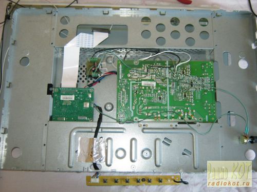
3. We have a view of the installation of the internal metal frame in the front of the case: 
We take out the board with the buttons from the latches, take out (in my case) the speaker connector and, bending the two latches at the bottom, take out the inner metal case.
4. On the left you can see 4 wires connecting the backlight lamps. We take them out by squeezing them slightly, because... To prevent it from falling out, the connector is made in the form of a small clothespin. We also remove the wide cable going to the matrix (at the top of the monitor), squeezing its connector on the sides (since the connector has side latches, although this is not obvious at first glance at the connector): 
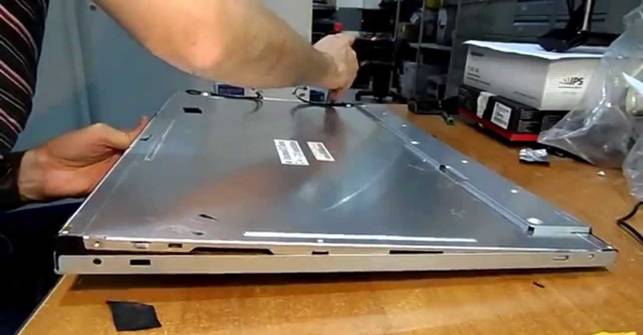
5. Now you need to disassemble the “sandwich” containing the matrix itself and the backlight: 
There are latches along the perimeter that can be opened by lightly prying with the same flat screwdriver. First, the metal frame holding the matrix is removed, after which you can unscrew three small bolts (a regular Phillips screwdriver will not work due to their mini size, you will need a particularly small one) holding the matrix control board and the matrix can be removed (it is best to place the monitor on hard surface, for example, a table covered with fabric with the matrix facing down, unscrew the control board, put it on the table, unfolding it through the end of the monitor and simply lift the backlit case, lifting it vertically up, and the matrix will remain lying on the table. You can cover it with something to prevent it from gathering dust, and assemble it in exactly the reverse order - i.e. cover the matrix lying on the table assembled body with backlight, wrap the cable through the end to the control board and, screwing the control board, carefully lift the assembled unit).
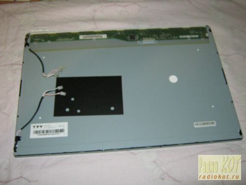
The matrix is obtained separately: 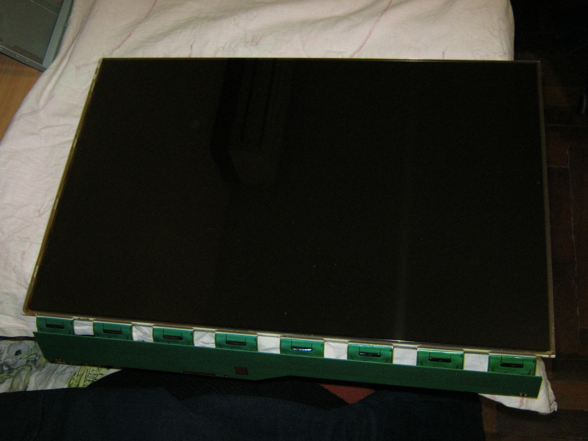
And the backlit block separately: 
The backlit unit is disassembled in the same way, only instead of a metal frame, the backlight is held by a plastic frame, which simultaneously positions the plexiglass used to diffuse the backlight light. Most of the latches are located on the sides and are similar to those that held the metal frame of the matrix (they open by prying them off with a flat-head screwdriver), but on the sides there are several latches that open “inward” (you need to press on them with a screwdriver so that the latches go inside the case).
At first I remembered the position of all the parts to be removed, but then it turned out that it would not be possible to assemble them “wrongly” and even if the parts look absolutely symmetrical, the distances between the latches on different sides metal frame and fixing tabs on the sides plastic frame holding the backlight will not allow them to be assembled “wrongly”.
That's all - we disassembled the monitor.
LED strip lighting
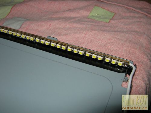
At first, it was decided to make the backlight from an LED strip with white LEDs 3528 - 120 LEDs per meter. The first thing that turned out to be is the width of the tape is 9 mm, and the width of the backlight lamps (and seat under the tape) - 7 mm (in fact, there are backlight lamps of two standards - 9 mm and 7 mm, but in my case they were 7 mm). Therefore, after examining the tape, it was decided to cut 1 mm from each edge of the tape, because this did not affect the conductive paths on the front part of the tape (and on the back, along the entire tape, there are two wide power cores, which will not lose their properties due to a decrease of 1 mm over a backlight length of 475 mm, since the current will be small). No sooner said than done: 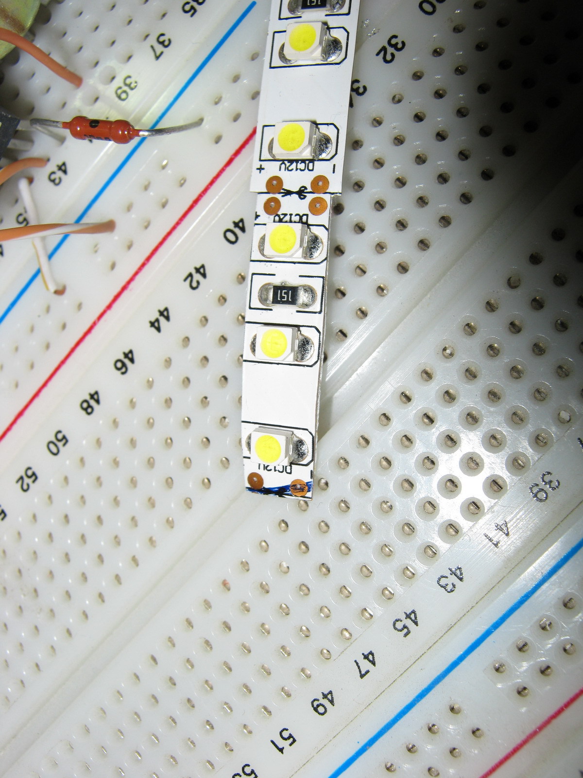
In the same way, the LED strip is carefully trimmed along its entire length (the photo shows an example of what happened before and what happened after trimming).
We will need two strips of 475 mm tape (19 segments of 3 LEDs per strip).
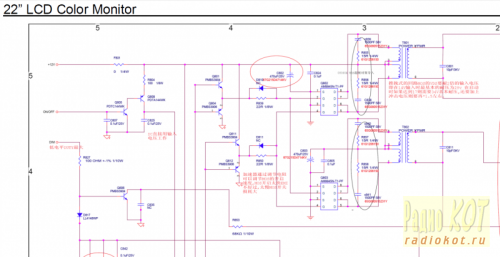
I wanted the monitor backlight to work the same way as the standard one (i.e. it was turned on and off by the monitor controller), but I wanted to adjust the brightness “manually”, as on old CRT monitors, because This is a frequently used function, and I got tired of navigating through on-screen menus pressing several keys every time (on my monitor, the right-left keys do not adjust the monitor modes, but the volume of the built-in speakers, so the modes had to be changed through the menu every time). To do this, I found a manual for my monitor on the Internet (for those who need it, it is attached at the end of the article) and on the page with the Power Board, according to the diagram, +12V, On, Dim and GND were found that are of interest to us. 
On - signal from the control board to turn on the backlight (+5V)
Dim - PWM backlight brightness control
+12V turned out to be far from 12, but somewhere around 16V without backlight load and somewhere around 13.67V with load
It was also decided not to make any PWM adjustments to the backlight brightness, but to power the backlight DC(at the same time, the issue is resolved that on some monitors the PWM backlight does not work very well high frequency and for some this makes their eyes a little more tired). In my monitor, the “native” PWM frequency was 240 Hz.
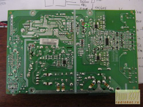
Further on the board we found contacts to which the On signal is sent (marked in red) and +12V to the inverter unit (the jumper that must be pulled out to de-energize the inverter unit is marked in green). (photo can be enlarged to see notes): ![]()
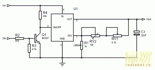
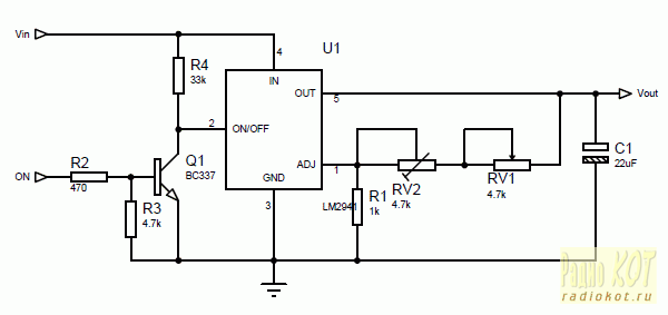
The LM2941 linear regulator was used as the basis for the control circuit, mainly because at a current of up to 1A it had a separate On/Off control pin, which was supposed to be used to control the backlight on/off with the On signal from the monitor control board. True, in LM2941 this signal is inverted (that is, there is voltage at the output when the On/Off input is zero potential), so we had to assemble an inverter on one transistor to match the direct On signal from the control board and the inverted input of LM2941. The scheme does not contain any other excesses: 
The output voltage for LM2941 is calculated using the formula:
Vout = Vref * (R1+R2)/R1
where Vref = 1.275V, R1 in the formula corresponds to R1 in the diagram, and R2 in the formula corresponds to a pair of resistors RV1+RV2 in the diagram (two resistors have been introduced for smoother brightness adjustment and reducing the range of voltages regulated by the variable resistor RV1).
I took 1kOhm as R1, and the selection of R2 is carried out according to the formula:
R2=R1*(Vout/Vref-1)
The maximum voltage we need for the tape is 13V (I took a little more than the nominal 12V so as not to lose brightness, and the tape will survive such a slight overvoltage). Those. maximum value R2 = 1000*(13/1.275-1) = 9.91 kOhm. The minimum voltage at which the tape still glows at least somehow is about 7 volts, i.e. minimum value R2 = 1000*(7/1.275-1) = 4.49 kOhm. Our R2 consists of a variable resistor RV1 and a multi-turn trimmer resistor RV2. The resistance of RV1 is 9.91 kOhm - 4.49 kOhm = 5.42 kOhm (we select the closest value of RV1 - 5.1 kOhm), and RV2 is set to approximately 9.91-5.1 = 4.81 kOhm (in fact, it is best to first assemble the circuit, set the maximum resistance of RV1 and measure the voltage at At the output of LM2941, set the resistance RV2 so that the output has the required maximum voltage (in our case, about 13V).
Installation of LED strip
Since after cutting the tape by 1 mm, the power conductors were exposed at the ends of the tape, I pasted electrical tape (unfortunately, not blue but black) onto the body in the place where the tape will be glued. The tape is glued on top (it is good to warm the surface with a hairdryer, because the tape sticks much better to a warm surface): 
Next, the back film, plexiglass and light filters that lay on top of the plexiglass are mounted. Along the edges I supported the tape with pieces of eraser (so that the edges on the tape did not come off): 
After that, the backlight unit is assembled in the reverse order, the matrix is installed in place, and the backlight wires are brought out.
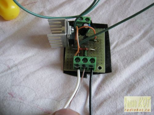
The circuit was assembled on a breadboard (due to simplicity, I decided not to wire the board), fastened with bolts through holes in back wall metal monitor case: 

Power and control signal On were supplied from the power supply board: 
The estimated power allocated to the LM2941 is calculated using the formula:
Pd = (Vin-Vout)*Iout +Vin*Ignd
For my case, it is Pd = (13.6-13)*0.7 +13.6*0.006 = 0.5 Watt, so it was decided to make do with the smallest radiator for the LM2941 (placed through a dielectric pad since it is not isolated from the ground in the LM2941).
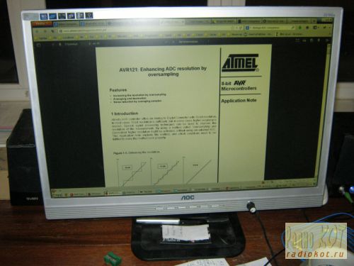
Final assembly demonstrated the functionality of the design: 
Among the advantages:
- Uses standard LED strip
- Simple control board
Disadvantages:
- Insufficient backlight brightness in bright conditions daylight(the monitor is in front of the window)
- The LEDs in the strip are not spaced closely enough, so small cones of light from each individual LED are visible near the top and bottom edges of the monitor
- The white balance is a little off and goes slightly greenish (most likely this can be solved by adjusting the white balance of either the monitor itself or the video card)
Quite good, simple and a budget option backlight repair. It’s quite comfortable to watch movies or use the monitor as a kitchen TV, but it’s probably not suitable for everyday work.
Adjusting brightness using PWM
For those Habro residents who, unlike me, do not remember with nostalgia the analogue brightness and contrast control knobs on old CRT monitors, you can make control from the standard PWM generated by the monitor control board without moving any additional controls outside (without drilling the monitor body). To do this, it is enough to assemble an AND-NOT circuit on two transistors at the On/Off input of the regulator and remove the brightness control at the output (set the output voltage to constant 12-13V). Modified scheme: 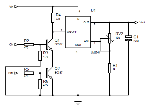
Trimmer resistor resistance
More dense LED backlight
To solve the problem of insufficient brightness (and at the same time uniformity) of the backlight, it was decided to install more LEDs and more often. Since it turned out that buying LEDs individually is more expensive than buying 1.5 meters of strip and unsoldering them from there, more was chosen economical option(unsolder the LEDs from the strip).
The 3528 LEDs themselves are placed on 4 strips 6 mm wide and 238 mm long, 3 LEDs in series in 15 parallel assemblies on each of the 4 strips (the layout of the boards for the LEDs is included). After soldering the LEDs and wires, the following is obtained: 
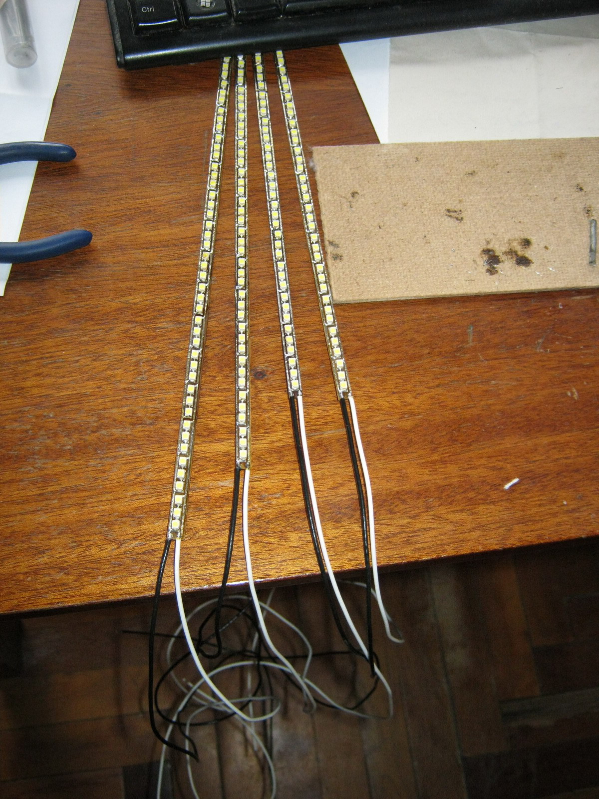
The strips are laid in twos at the top and bottom with wires to the edge of the monitor at the joint in the center: 

The nominal voltage on the LEDs is 3.5V (range from 3.2 to 3.8 V), so an assembly of 3 serial LEDs should be powered by a voltage of about 10.5V. So the controller parameters need to be recalculated: 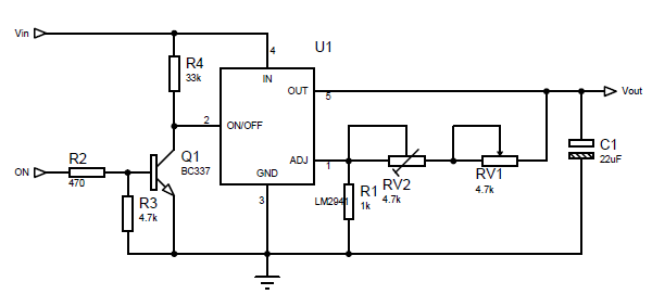
The maximum voltage we need for the tape is 10.5V. Those. maximum value R2 = 1000*(10.5/1.275-1) = 7.23 kOhm. The minimum voltage at which the LED assembly still glows at least somehow is about 4.5 volts, i.e. minimum value R2 = 1000*(4.5/1.275-1) = 2.53 kOhm. Our R2 consists of a variable resistor RV1 and a multi-turn trimmer resistor RV2. Resistance RV1 is 7.23 kOhm - 2.53 kOhm = 4.7 kOhm, and RV2 is set to approximately 7.23-4.7 = 2.53 kOhm and adjusted to assembled circuit to obtain 10.5V at the output of LM2941 at maximum resistance RV1.
One and a half times more LEDs consume 1.2A of current (nominally), so the power dissipation on the LM2941 will be equal to Pd = (13.6-10.5)*1.2 +13.6*0.006 = 3.8 Watt, which already requires a more solid heatsink for heat removal: 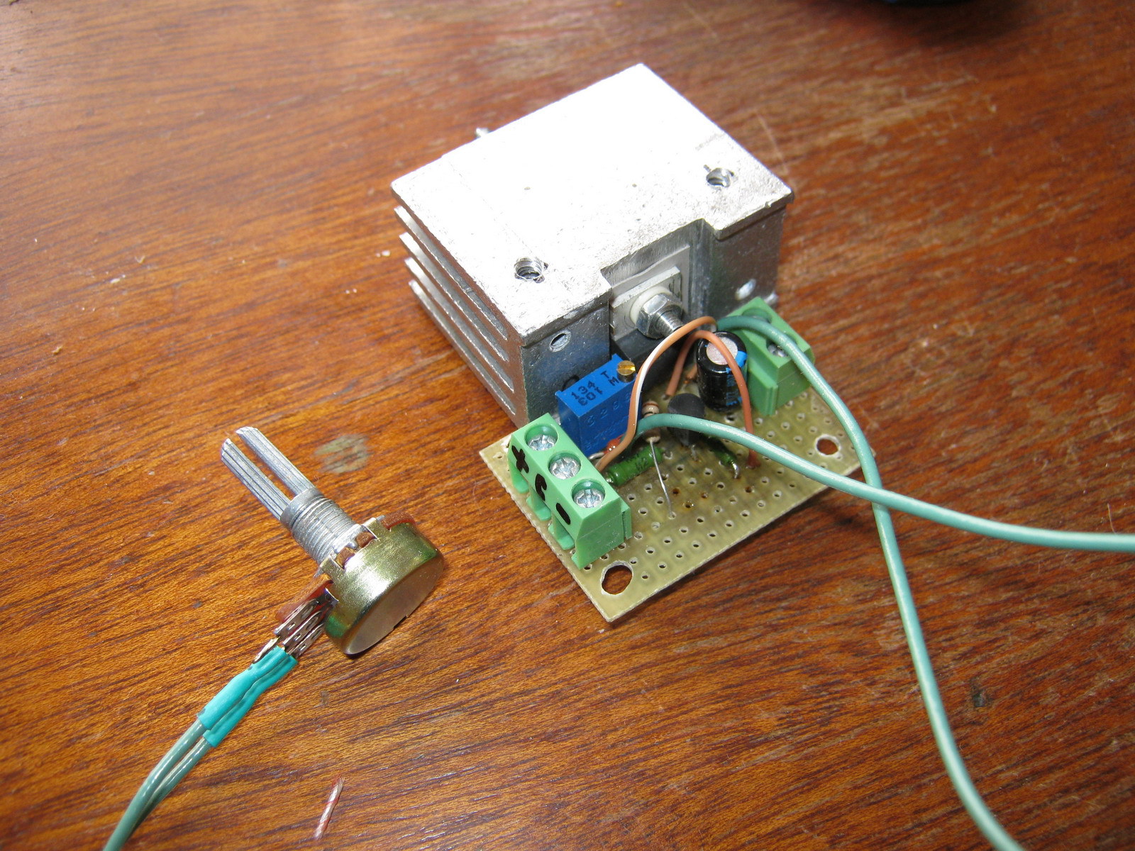
We collect, connect, we get much better: 
Advantages:
- Quite high brightness (possibly comparable, and perhaps even superior to the brightness of the old CCTL backlight)
- The absence of light cones at the edges of the monitor from individual LEDs (LEDs are located quite often and the backlight is uniform)
- Still a simple and cheap control board
Flaws:
- The issue with the white balance, which goes into greenish tones, has not been resolved
- LM2941, although with a large heatsink, gets hot and heats everything inside the case
Control board based on step-down regulator
To eliminate the heating problem, it was decided to assemble a brightness controller based on a Step-down voltage regulator (in my case, an LM2576 with a current of up to 3A was chosen). It also has an inverted On/Off control input, so for matching there is the same inverter on one transistor: ![]()
Coil L1 affects the efficiency of the converter and should be 100-220 µH for a load current of about 1.2-3A. The output voltage is calculated using the formula:
Vout=Vref*(1+R2/R1)
where Vref = 1.23V. For a given R1, you can obtain R2 using the formula:
R2=R1*(Vout/Vref-1)
In calculations, R1 is equivalent to R4 in the circuit, and R2 is equivalent to RV1+RV2 in the circuit. In our case, to adjust the voltage in the range from 7.25V to 10.5V, we take R4 = 1.8 kOhm, variable resistor RV1 = 4.7 kOhm and the tuning resistor RV2 is 10 kOhm with an initial approximation of 8.8 kOhm (after assembling the circuit, it is best to set it exact value measuring the voltage at the output of LM2576 at maximum resistance RV1).
I decided to make a board for this regulator (the dimensions did not matter, since there is enough space in the monitor to mount even a large board): 
Control board assembly: 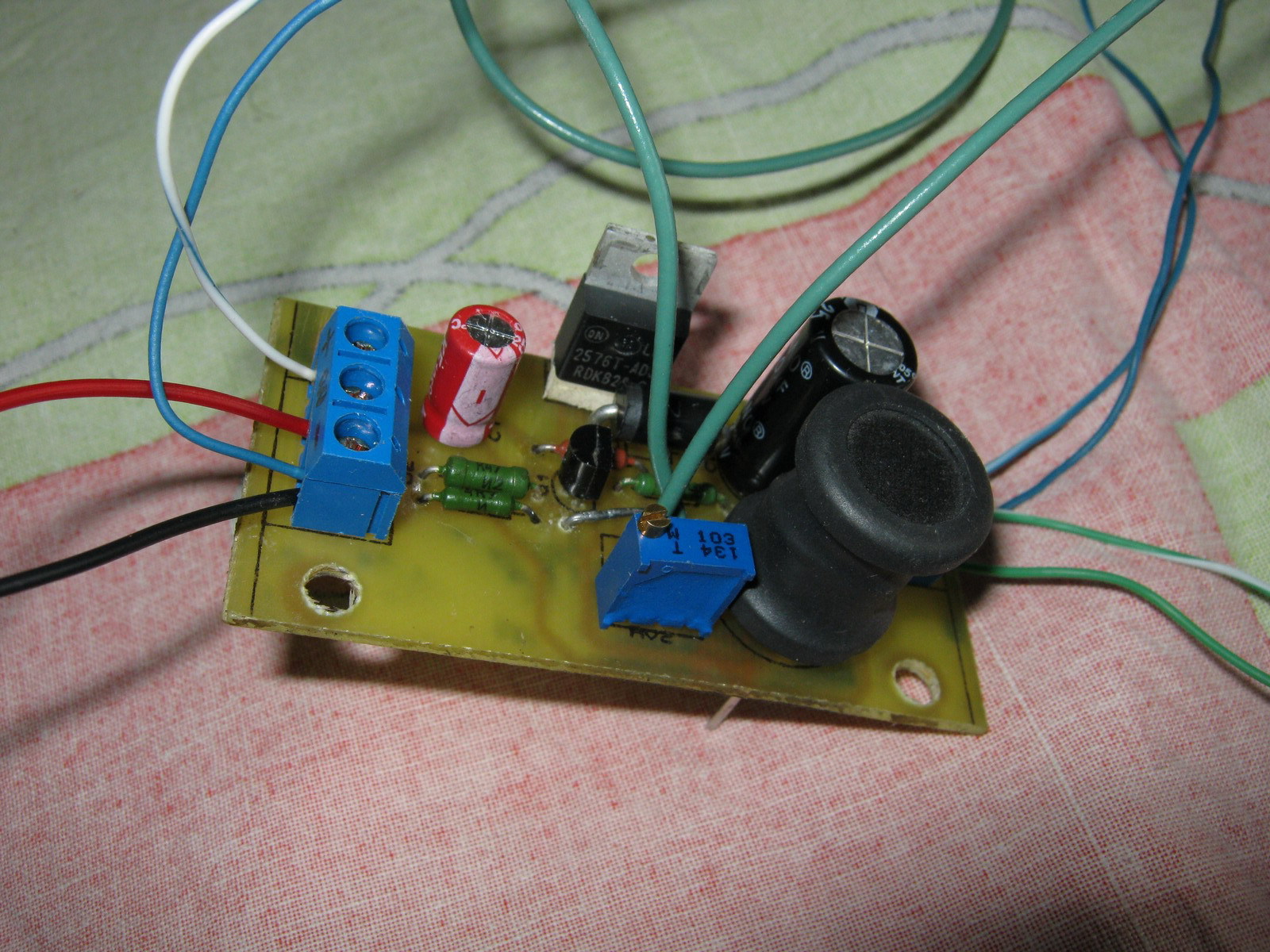
After installation in the monitor: ![]()
Everyone is here: 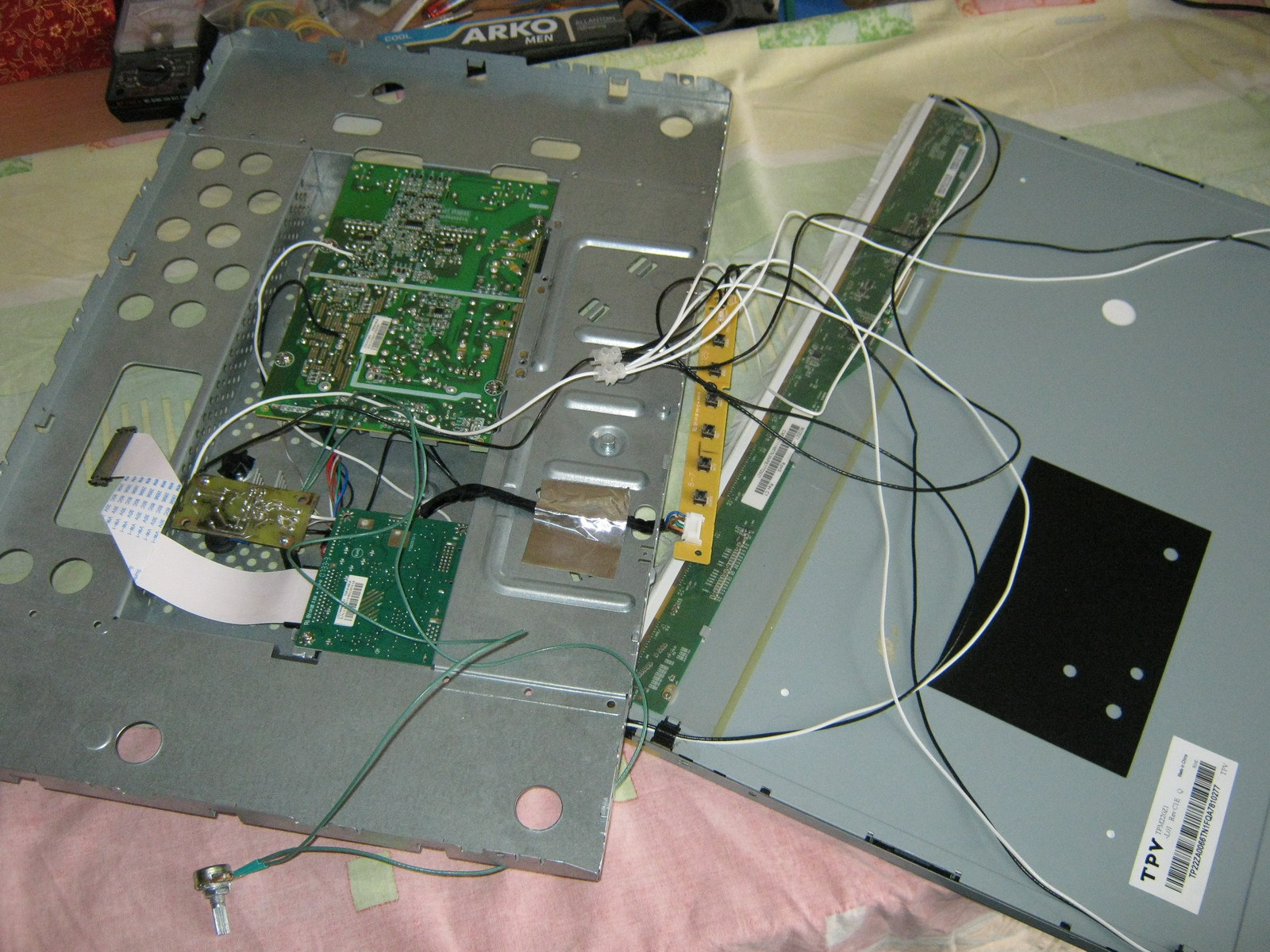
After assembly everything seems to work: 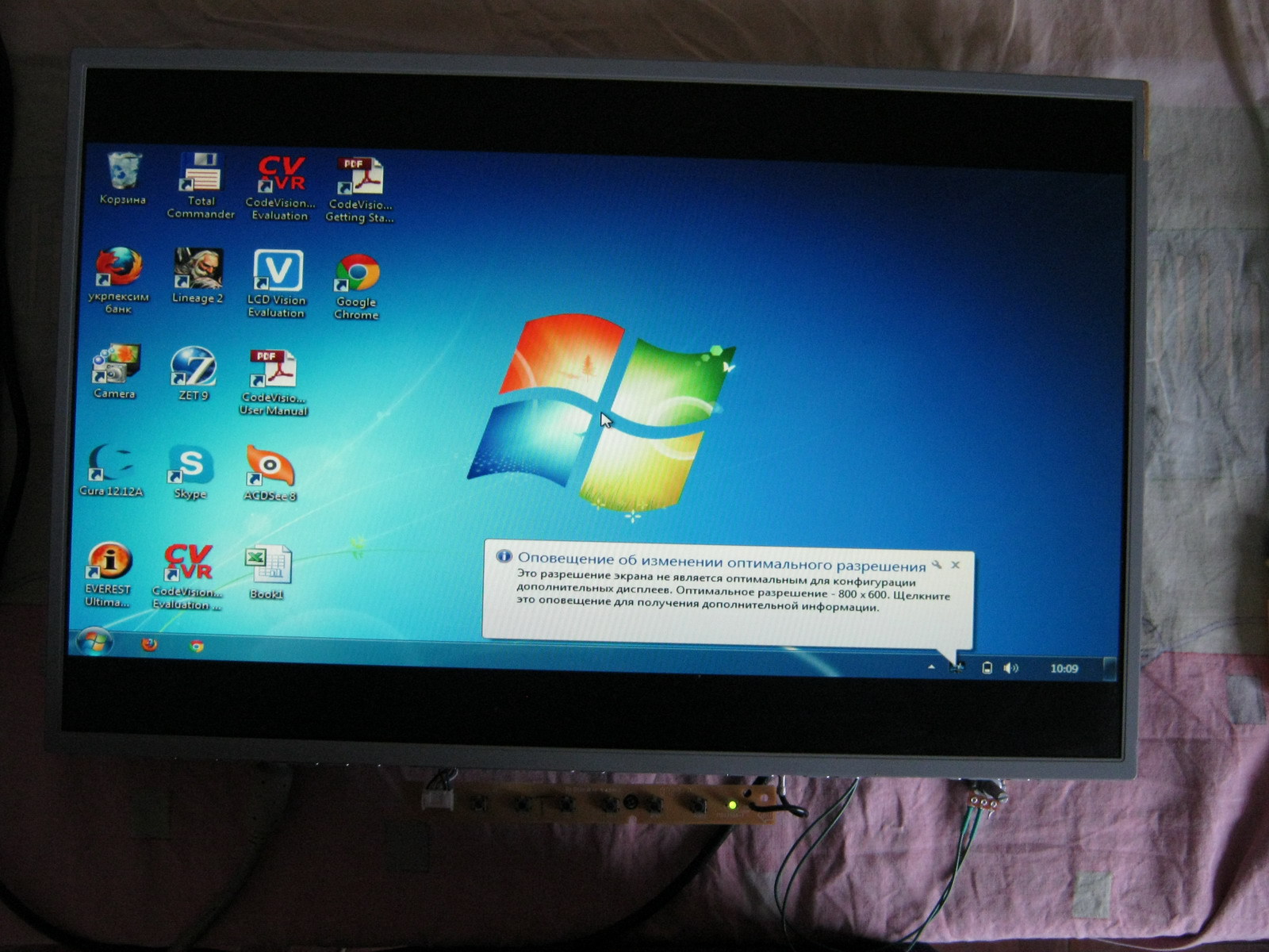
Final option: 
Advantages:
- Sufficient brightness
- Step-down regulator does not heat up and does not warm up the monitor
- There is no PWM, which means nothing blinks at any frequency
- Analogue (manual) brightness control
- No restrictions on minimum brightness (for those who like to work at night)
Flaws:
- The white balance is slightly shifted towards green tones (but not much)
- At low brightness (very low), unevenness in the glow of LEDs of different assemblies is visible due to the spread of parameters
Improvement options:
- White balance is adjustable both in the monitor settings and in the settings of almost any video card
- You can try installing other LEDs that will not noticeably disrupt the white balance
- To eliminate the uneven glow of LEDs at low brightness, you can use: a) PWM (adjust the brightness using PWM by always supplying the rated voltage) or b) connect all the LEDs in series and power them with an adjustable current source (if you connect all 180 LEDs in series, you will need 630V and 20mA), then the same current should pass through all the LEDs, and each one will have its own voltage drop; the brightness is regulated by changing the current and not the voltage.
- If you want to make a PWM-based circuit for LM2576, you can use a NAND circuit at the On/Off input of this Step-down regulator (similar to the above circuit for LM2941), but it is better to put a dimmer in the gap of the negative wire of the LEDs via a logic-level mosfet
Any equipment has its own service life. LCD monitors are no exception either. A very common problem with them is the failure of the screen backlight lamps. In this case, you should not rush to write him off. You can repair your monitor by replacing the matrix backlight lamp. When searching necessary details It is not always possible to find the required CCFL lamps (fluorescent). Replacing your old LCD monitor backlight with LED is not difficult. There are plenty of necessary spare parts on sale; you can use a strip of LEDs.
Replacing the monitor backlight with LED
Backlight repairs should be carried out following certain rules and the sequence of work. First you need to make sure whether the backlight of the monitor matrix has really failed, because not only it can be responsible for the supply of light. Most often, such a breakdown is manifested by a blackout monitor, which can be not only a computer monitor, but also a TV monitor. It may also turn on and then go off after a few seconds. To identify this problem, you will need to disassemble the monitor.
Disassembling a PC or TV monitor
It is not that difficult to describe the process in detail, but each model and brand has its own characteristics, sizes and is assembled differently. However, the assembly principle is approximately the same. You can briefly describe the disassembly of the monitor.
It is necessary to remove the stand by unscrewing the screws that hold it, as well as the remaining fastening elements of the case.
At the end of the device there is a special groove, which is designed to open the latches by prying the cover with a flat object. When disassembling the monitor for the first time, you will notice that the latches fit tightly, but the next time you open it, the process will be easier.
Now you need to remove metal carcass. To do this, you need to bend the latches or unscrew the screws from the case. For those who have already changed any parts on similar equipment, this procedure will not seem difficult. After removing the metal case, disconnect the wires from the board.
Once these steps are completed, the matrix will become available. It has connecting cables, due to the fragility of which you need to be extremely careful with it. It is advisable to remove the matrix to the side and cover it with something to prevent accidental damage and accumulation of dust. If the work is done correctly, you can easily reach the inverter, electronic board and lamps. If you decide to redo the backlight for your monitor, you should remember the location of all the parts to be removed, although it will be difficult to confuse them.

Next, you need to disconnect each lamp directly from the matrix. When the grooves are removed, the backlight sources can be removed from there and simply thrown away. Anyone who has not yet converted the backlight for monitors from CCFL to LEDs should know that due to the presence of mercury in CCFL lamps you need to be extremely careful when working with them. The next step The monitor backlight will be replaced using LED strip.
DIY monitor backlight
To begin with, before replacing the backlight bulbs, you need to purchase a strip with LEDs. It's better to buy it already taken dimensions from lamps or take a tape a little longer. There should be at least 120 LEDs per meter, and it is better to choose a color that does not put pressure on the eyes.
LEDs that illuminate the monitor in white are ideal. You can choose a tape with crystals 3528 and 4115. Its size must correspond to the mounting location where the LED backlight of a PC or TV monitor will be mounted. Usually standard size is 7 mm. The kit for replacing CCFL monitor backlight lamps with LEDs can be equipped with different amounts LEDs, but their performance and service life are much higher than older light sources.
removed lamps, in their groove. You can use old wires from removed lamps to further connect them to the power source. In such situations, it is better to check whether the LED backlight circuit is assembled correctly. To do this, you can connect it using wires to an external power source, for example, a battery.
The next step is to connect new lighting to the power board installed on both PC and TV displays. To ensure that the modification does not fail, you should pay close attention to this point. Anyone who has connected low-current devices to a network with a voltage higher than necessary knows that the device will burn out. This will happen due to the fact that the resistance of the device is designed for smaller values. So, you will need to find the 12 V pins on the board and solder the wires from the new one to them LED backlight, it is necessary to observe their polarity. Now you can start assembling your TV or PC display.
Do-it-yourself LED backlighting in the monitor has one significant drawback. Since the connection is made directly, there is no adjustment or disconnection. Therefore, it is constantly on when the monitor is on. Such a bright glow will dazzle and annoy the person looking at the screen.

To create a backlight control, you need to re-energize the wires connected to the strips, with the ability to turn it on and off using certain buttons. There are 2 ways to accomplish this task:
- You will need to assemble a circuit that will be used to adjust the power and intensity of the backlight. To do this you need:
- Find the plastic connector located on the power supply board of the monitor or TV display. It is not difficult to recognize it - wires will come out of it with a socket labeled for each of them.
- To ensure switching on and off, you need to use the “DIM” sockets. Brightness adjustment occurs by changing the well in the PWM controller.
- Now you need to find field-effect transistor with channel N. After this, the negative wires are soldered from the LED strip to the terminal (Drain) of the field switch. The common wire from the LEDs is connected to the input element (Source). The circuit provides for the use of a resistor with a value of 100 to 2,000 Ohms, through which the Gate of the transistor is connected to any “DIM” socket.
- All that remains is to solder the positive wires from the LED backlight. To do this, you should connect them to a 12 V power chip, and then solder them.
- After completing all of the above steps, you can install the backlight in the mounting locations and begin assembling the monitor in the reverse order. It is worth remembering to be careful with the matrix and filters. After assembly, the device is ready for use.

- The second method is to use LED strips with inverters built into them:
- To connect the circuit with this method, you will again need a plastic connector with a DIM socket, as well as an on/of pin. It is better to determine this socket by pinout.
- When using a multimeter, the sockets on the control unit, which was responsible for the monitor backlights, are called up. The signal must pass from them to the DIM and on/of sockets.
- The next step is to solder the wires of the LED strip inverters to the found sockets. To adjust the backlight using an inverter from LEDs, you will need to remove the wires that power the old lamps.
- You can secure it wherever there is free space using double-sided tape.
- To complete the modification, all that remains is to assemble the monitor and test the new backlight in practice.
Converting the monitor backlight from lamp to LED in this way ensures its longer performance and efficiency, which, of course, will please every user.
As you know, modern LCD monitors work to “transmit” light - a translucent picture on the matrix is illuminated from behind, the light passing through the matrix and its light filters forms an image. A fairly bright source of white light is used as backlight - the light transmission matrix is more reminiscent of rather dark sunglasses.
Traditionally, cold cathode fluorescent lamps, or CCFL – Cold Cathode Fluorescent Lamps, have been used for this. These lamps are glass tubes with a diameter of 2-3 mm, inner surface which are coated with phosphor. The tubes are filled with mercury vapor. When an electric discharge passes through the gas, radiation is generated, causing the phosphor to glow. To operate such a lamp, a high alternating voltage is required - about 1500 V with a frequency of about 40-50 kHz.
Among the most common malfunctions of liquid crystal panels is the failure of the backlight or inverter - a device that converts direct voltage (usually 12-18 V, depending on the monitor's power supply) into alternating voltage to operate the lamp. This manifests itself in a sharp decrease in the brightness of the screen, usually from one of the edges, or in the complete shutdown of the backlight - in this case, the image on the screen is barely visible.
In branded services, such faults are “cured” by replacing the entire panel, especially in the case of laptop panels. It’s quite expensive, but in the case of a monitor, it’s easier to buy a new one. Fortunately, there are not only branded services in the world, but also a considerable number of “craftsmen” who have mastered the operation of replacing backlights or inverters.
Replacing the backlight lamp is a simple operation, which is provided “structurally” in some monitors. If anyone hasn’t read Igor Pichugin on RadioKot, I’ll give a short “squeeze” from it.
The lamps are mounted along one side of the display in a “pencil case”. Typically, removing the pencil case requires disassembling the LCD panel, that is, removing the metal casing and the panel itself. A thin (about 0.5-1 mm) control board is mounted behind the panel, connected to the matrix itself by several cables. To remove the LCD screen, you must carefully peel it off (do not cut it under any circumstances! Damaged data lines on flexible cables cannot be restored) protective film.
To demonstrate “classic” backlight technology, I use an LG Flatron L1970H LCD monitor.
Let's start disassembling the monitor by removing the stand. You need to remove the plastic casing from the back that covers the backlight mount and the cables from the connectors on the stand.
After removing the stand, remove the LCD module from the case. The front frame is secured with latches and can be easily separated from the rear of the case.
The LCD module is covered with a metal casing. Through the holes in it, inverter transformers with menacing inscriptions are visible.
Unscrew the screws securing the casing.
Now you can see the board in detail control electronics monitor and an inverter made as a separate unit.
The electronics board is connected by a separate harness to the LCD matrix decoder, covered with a thin self-adhesive film.
The decoder is connected to the matrix using thin flexible cables. If you have to remove the panel, carefully peel off the protective film - the flexible data lines cannot be restored, in which case the matrix will have to be thrown away.
The inverter mounted behind the monitor can often be replaced with a similar one. It is enough to know the supply voltage and the number of lamps. In addition, the inverter in monitors is usually large and repairable.
The lamps will be connected to the inverter using standard connectors.
In this monitor, the lamp cases can be removed without disassembling the panel. You just need to unscrew the screw...
...and pull out the pencil case.
The lamps are mounted in canisters of two. A sign of an “old” lamp is black rings around the cathodes. In burnt-out lamps they are much wider and darker.
It was no coincidence that I needed lamps. They brought a battered Fujitsu-Siemens Amilo M7800 laptop to “look at” with a diagnosis of “very dark image on the screen.” The company service asked for some unrealistic money for repairs - apparently they were going to change the matrix. I had just read an article on “cat” and was going to try changing the lamp.
To access the LCD panel, the first step is to remove its frame. Usually it is secured with latches, but some laptop models may also have screws hidden under rubber plugs.
At the bottom of the laptop's LCD screen, between the hinges, is the inverter in a protective housing.
It makes sense to check whether the lamp is really faulty, or whether the inverter has failed. To do this, just connect a known-good lamp to the inverter.
Laptop inverters are quite miniature and in case of malfunction they are usually replaced entirely. Replacement with a similar one from another model is acceptable, since they are available both at radio flea markets and at Dealextreme.
When replacing an inverter, it is advisable to determine how the on/off and backlight brightness are controlled. Typically, for this purpose, the cable going to the inverter contains DIM signals (brightness control, usually varying from 1 V - the lowest brightness to 3 V - the highest) and ENABLE (0 V - backlight off, 3 V - backlight on). Usually they correct connection not necessary for the operation of the new inverter, but allows you to retain some energy saving features.
To replace the lamp we will need to remove the LCD panel. You need to unscrew the screws that secure it to the hinges and lid of the laptop.
There are metal guides on the sides of the panel that must be removed for further disassembly.
In the panel used in this laptop, you can get to the lamp without disassembling the entire panel. You just need to remove one side of the metal frame and open the plastic case.
It would seem that the next step is obvious - we go to the radio market, buy the necessary lamp and put it in the laptop. The reality turned out to be somewhat more complicated. On Mitino there were no lamps of suitable length; they were either very short (15 mm shorter) or very long (15 mm longer). In the stall of the Istok-2 company (this is a stall with radio tubes and all sorts of lighting equipment, located at the end farthest from the entrance ground floor, glows like Christmas tree) advised to use a line of super-bright LEDs.
The width of such a ruler is about 3 mm. The diodes on it are installed in groups of 3 pieces, each about 15 mm long. Accordingly, you can cut the ruler required length with acceptable accuracy.
Now, with the development of manufacturing technologies powerful LEDs white glow, LED backlighting began to be installed in some LCD monitors and televisions. In fact, anyone can join the “leading edge” of technology by installing such lighting to replace the burnt-out “lamp” one. Yielding to the persuasion of the “originists,” I bought a ruler 300 mm long for 250 rubles (approximately the cost of the lamp).
The LED line fits wonderfully inside a standard pencil case.
To check the LED backlight, simply connect the ruler inserted into the matrix to a suitable power source. When turned off, the screen should glow milky white.
Reassemble in reverse order (c).
Instead of an inverter thrown out as unnecessary, you can assemble a circuit like this:
We select resistor values depending on the parameters of the DIM and ENABLE signals and the supply voltage.
In conclusion, I want to say a few words about why LED backlighting is disgusting.
Firstly, the emission spectrum of LEDs does not quite match the spectrum of lamps. Therefore, on monitors designed for working with graphics, such a replacement can only do harm.
Secondly, sometimes there are “smart” inverters controlled by digital signals (usually via the I2C bus, but there are also more exotic ones). If there is no inverter, the LCD panel may not turn on.
Thirdly, the main disadvantage of LED backlighting assembled “on the knee” is some unevenness of the glow near the lamp.
It is noticeable in the photo that the illumination of the lower part of the screen is not very uniform, and the lower right corner is generally dark; unfortunately, the ruler turned out to be a little short.
In any case, replacing a CCFL lamp with LEDs is affordable and inexpensive way restoration of LCD monitors. The existing shortcomings cannot be called critical, but in the case of lamps of non-standard sizes, like mine, this is quite justified.
The entry was published on the blog of Shura Lyuberetsky. You can leave your comments there using your LiveJournal username (OpenID login).
Liquid crystal displays (LCDs) are passive information display devices. In order for the formed image to be perceived by the human eye, it must be illuminated, in the simplest case - with natural external light. In case of insufficient natural light or its absence, an artificial light source can be used for the display.
Most modern LCDs operate in one of three display modes: total reflection mode, in which external light reflected from a reflector located behind the display (Fig. 1, a); in the semi-reflection mode, in which the reflector reflects external light, but is capable of transmitting light from a light source located behind it (Fig. 1, b); in the backlight mode, in which there is no reflector reflecting external light and a special light source is used to illuminate the image (Fig. 1, c).
Rice. 1. LCD display modes
A technique that uses a special light source is called “backlight”. To implement backlighting, several technologies are used, which will be discussed below.
Electroluminescent (EL) backlight
Electroluminescent illumination provides uniform illumination and is made in a thin and light design (Fig. 2).

Rice. 2. Electroluminescent backlight design
This illumination provides various colors, including white, most often used in LCDs. Consumption with electroluminescent illumination is relatively low, but its organization requires an alternating voltage source of 80...100 V with a frequency of about 400 Hz (typical value). DC/DC converters are used as such a source, transforming a direct current voltage of 5, 12 or 24 V into an alternating voltage of the required value. This is the most energy-efficient type of backlight and is most often used in battery-powered devices. The lifespan of electroluminescent backlight (brightness reduced by half from the original) is about 3...5 thousand hours and depends on the set brightness (Fig. 3).

Rice. 3. Lifespan of EL backlight, dependence of lifespan on set brightness
Distinctive features of electroluminescent backlight:
- a flat light source with a maximum thickness of 1.3 mm (1.5 mm including leads) provides uniform illumination of a large area;
- wide supply voltage range alternating current(maximum value 150 V) with a frequency of 60…1000 Hz. If boost converters are available, it can be powered by a single battery with a voltage of 1.5 V;
- glow color: green-blue, yellow-green and white;
- performance characteristics of typical power modules: output voltage 110 V with a frequency of 400 Hz; load current 8 mA (at Ta = 20 °C and relative humidity 60%);
- operating temperature range - from 0 to 50 °C;
- storage temperature range from -20 to 60 °C.
Light-emitting diode (LED) backlight
LED backlighting is characterized by the longest service life - at least 50 thousand hours - and greater brightness than EL backlighting. The backlight is provided by solid state devices and can therefore be operated directly from a 5V voltage source without the use of converters. However, to limit the current through the LED, current limiting resistors must be installed. A chain of LEDs is located along the side surfaces of the display or in the form of a matrix under the diffuser (scatterer) and provides bright, uniform illumination (Fig. 4, a, b).
Rice. 4. Designs of matrix and side LED lighting
Side illumination is used in modules with the number of characters in a row up to 20. When the number of characters is over 20, a darker area is formed in the center of the LCD than at the edges. To eliminate this drawback, use special measures, for example, additional lighting from above.
Matrix LED backlighting provides brighter, more uniform light. When designing such lighting, consumption is a determining factor. It is not recommended for use in battery-powered devices that require the backlight to be on at all times.
LED backlights operate at a supply voltage of 4.2 V (typical value). Backlight consumption is determined by the number of LEDs turned on, and therefore, as the display size increases, consumption increases, ranging from 30 to 200 mA or more.
The color of LED backlight can be different, including white, but yellow-green backlight is most often used. Its light emission is higher than that of EL backlight. It is possible to control the brightness of the light using a potentiometer or PWM controller.
Taking into account the cost of converters used with EL, the use of LED backlighting is more economical. The thickness of a module with LED backlight is 2–4 mm thicker than that of a module with EL backlight or without backlight.
Distinctive features of LED backlight:
- low supply voltage, no need to use special converters;
- long life cycle- on average over 100 thousand hours;
- Possibility of backlighting red, green, orange and white flowers or multi-color backlight (switchable);
- side or matrix lighting;
- typical supply voltage - 4.2 V; consumption 30 to - 200 mA and above; brightness - 250 cd/m;
- no noise generation.
Cold cathode fluorescent lamp (CCFL) backlighting
CCFL backlighting is characterized by relatively low consumption and very bright White light. Two technologies are used: direct and side illumination (Figure 5, a, b).
Rice. 5. Designs for direct and side illumination with cold cathode fluorescent lamps
In both cases, the light source is cold cathode fluorescent lamps (local light spot sources), the light from which is distributed over the entire screen area by diffusers and light guides. Side lighting makes it possible to implement modules of small thickness and with lower consumption. CCFL backlighting is used primarily in graphic LCDs, and the service life of CCFL backlighting is higher than that of EL backlighting - up to 10–15 thousand hours.
CCFL provides illumination of large surfaces, so it is used primarily in large flat panel displays. The great advantage of CCFL is the ability to produce paper-white color, which makes CCFL practically the only source of backlight for color displays. Fluorescent lamps require converters with an AC output voltage of 270 to 300 V to operate.
Distinctive features of backlighting with cold cathode fluorescent lamps (CCFL):
In table Tables 1–3 show the characteristics of cold cathode fluorescent lamps.
Table 1. Maximum values
Table 2. Electrical characteristics
Table 3. Optical characteristics
In the table below. 4 given comparative characteristics three main types of backlight and their main areas of application.
Table 4.
| Backlight type | Use tion, depending on lighting conditions |
Consumption | Price | RFI generation | Brightness control | Notes |
| No | Not applicable in low light conditions | Best (does not consume by nature) | Least | Absent | Not used | |
| EL | Very good 30 mW | Average | Minor (at low frequencies) | Fixed brightness | Prefer Suitable for battery powered devices |
|
| LED | Can be used in all lighting conditions | Good 60 mW | Average | Absent | Adjustable to wide range | Most often used in small displays |
| CCFL | Not suitable for use in bright lighting conditions | Substantial 700 mW | The tallest | Sometimes (at high frequency) | Adjustable within a limited range | Most often used in large graphic displays |
Time passes unnoticed and seemingly recently purchased equipment is already breaking down. So, having worked their 10,000 hours, the lamps of my monitor (AOC 2216Sa) gave up their life. At first, the backlight did not turn on the first time (after turning on the monitor, the backlight turned off after a few seconds), which was solved by turning the monitor on/off again; over time, the monitor had to be turned off/off 3 times, then 5, then 10, and at some point it could not turn on the backlight, regardless of the number of attempts to turn it on. The lamps brought to the light of day turned out to have blackened edges and were legally thrown into scrap. An attempt to install replacement lamps (new lamps of the appropriate size were purchased) was unsuccessful (the monitor was able to turn on the backlight several times, but quickly went into on-off mode again) and finding out the reasons for what the problem could be in the electronics of the monitor led me to the idea that it will be easier to assemble your own monitor backlight using LEDs than to repair the existing inverter circuit for CCFL lamps, especially since there have already been articles on the Internet showing the fundamental possibility of such a replacement.
Disassembling the monitor
Many articles have already been written on the topic of disassembling a monitor; all monitors are very similar to each other, so in brief:
1. Unscrew the monitor delivery mount and the only bolt at the bottom that holds the back wall of the case
2. At the bottom of the case there are two grooves between the front and back of the case, insert a flat-head screwdriver into one of them and begin to remove the cover from the latches along the entire perimeter of the monitor (simply turning the screwdriver carefully around its axis and thereby lifting the case cover). There is no need to exert excessive effort, but it is difficult to remove the case from the latches only the first time (during the repair I opened it many times, so the latches became much easier to remove over time).
3. We have a view of the installation of the internal metal frame in the front part of the housing:

We take out the board with the buttons from the latches, take out (in my case) the speaker connector and, bending the two tabs at the bottom, take out the inner metal case.
4. On the left you can see 4 wires connecting the backlight lamps. We take them out by squeezing them slightly, because... To prevent it from falling out, the connector is made in the form of a small clothespin. We also remove the wide cable going to the matrix (at the top of the monitor), squeezing its connector on the sides (since the connector has side latches, although this is not obvious at first glance at the connector):

5. Now you need to disassemble the “sandwich” containing the matrix itself and the backlight:
There are latches along the perimeter that can be opened by lightly prying with the same flat screwdriver. First, the metal frame holding the matrix is removed, after which you can unscrew three small bolts (a regular Phillips screwdriver will not work due to their miniature size, you will need a particularly small one) holding the matrix control board and the matrix can be removed (it is best to place the monitor on a hard surface, such as a table covered with the fabric facing down, unscrew the control board, place it on the table, unfolding it through the end of the monitor, and simply lift the backlit case, lifting it vertically up, and the matrix will remain lying on the table. It can be covered with something so as not to gather dust, and assembled exactly the opposite way. order - i.e. cover the matrix lying on the table with the assembled case with backlight, wrap the cable through the end to the control board and, screwing the control board, carefully lift the assembled unit).
The matrix is obtained separately:
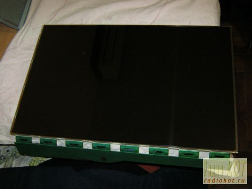
And the backlit block:

The backlit block is disassembled in the same way, only instead of a metal frame, the backlight is held by a plastic frame, which simultaneously positions the plexiglass used to diffuse the backlight light. Most of the latches are on the sides and are similar to those that held the metal frame of the matrix (they open by prying them off with a flat-head screwdriver), but on the sides there are several latches that open “inward” (you need to press on them with a screwdriver so that the latches go inside the case).
At first I remembered the position of all the parts to be removed, but then it turned out that it would not be possible to assemble them “wrongly” and even if the parts look absolutely symmetrical, the distances between the latches on different sides of the metal frame and the locking protrusions on the sides of the plastic frame holding the backlight will not allow them to be assembled “wrongly” ".
That's all - we disassembled the monitor.
LED strip backlighting
At first, it was decided to make the backlight from an LED strip with white LEDs 3528 - 120 LEDs per meter. The first thing that turned out to be is that the width of the tape is 9 mm, and the width of the backlight lamps (and the seat for the tape) is 7 mm (in fact, there are backlight lamps of two standards - 9 mm and 7 mm, but in my case they were 7 mm). Therefore, after examining the tape, it was decided to cut 1 mm from each edge of the tape, because this did not affect the conductive paths on the front part of the tape (and on the back, along the entire tape, there are two wide power cores, which will not lose their properties due to a decrease of 1 mm over a backlight length of 475 mm, since the current will be small). No sooner said than done:

In the same way, the LED strip is carefully trimmed along its entire length (the photo shows an example of what happened before and what happened after trimming).
We will need two strips of 475 mm tape (19 segments of 3 LEDs per strip).
I wanted the monitor backlight to work the same way as the standard one (that is, it was turned on and off by the monitor controller), but I wanted to adjust the brightness “manually”, as on old CRT monitors, because This is a frequently used function, and I got tired of navigating through on-screen menus pressing several keys every time (on my monitor, the right-left keys do not adjust the monitor modes, but the volume of the built-in speakers, so the modes had to be changed through the menu every time). To do this, I found a manual for my monitor on the Internet (for those who need it, it is attached at the end of the article) and on the page with the Power Board, according to the diagram, +12V, On, Dim and GND were found that are of interest to us.
On - signal from the control board to turn on the backlight (+5V)
Dim - PWM backlight brightness control
12V turned out to be far from 12, but somewhere around 16V without a backlight load and somewhere around 13.67V with a load
It was also decided not to make any PWM adjustments to the backlight brightness, but to power the backlight with direct current (at the same time, the issue is resolved that on some monitors the PWM backlight operates at a not very high frequency and for some this makes their eyes a little more tired). In my monitor, the “native” PWM frequency was 240 Hz.
Further on the board we found contacts to which the On signal is sent (marked in red) and +12V to the inverter unit (the jumper that must be pulled out to de-energize the inverter unit is marked in green). (photo can be enlarged to see notes):
The basis of the control circuit was to take the linear regulator LM2941 mainly because, with a current of up to 1A, it had a separate On/Off control pin, which was supposed to be used to control the on/off of the backlight with the On signal from the monitor control board. True, in LM2941 this signal is inverted (i.e., there is voltage at the output when the On/Off input is zero potential), so we had to assemble an inverter on one transistor to match the direct On signal from the control board and the inverted input of LM2941. The scheme does not contain any other excesses:
The output voltage for LM2941 is calculated using the formula:
Vout = Vref * (R1+R2)/R1
where Vref = 1.275V, R1 in the formula corresponds to R1 in the diagram, and R2 in the formula corresponds to a pair of resistors RV1+RV2 in the diagram (two resistors were introduced for smoother brightness adjustment and reducing the range of voltages regulated by the variable resistor RV1).
I took 1kOhm as R1, and the selection of R2 is carried out according to the formula:
R2=R1*(Vout/Vref-1)
The maximum voltage we need for the tape is 13V (I took a little more than the nominal 12V so as not to lose brightness, and the tape will survive such a slight overvoltage). Those. maximum value R2 = 1000*(13/1.275-1) = 9.91 kOhm. The minimum voltage at which the tape still glows at least somehow is about 7 volts, i.e. minimum value R2 = 1000*(7/1.275-1) = 4.49 kOhm. Our R2 consists of a variable resistor RV1 and a multi-turn trimmer resistor RV2. The resistance of RV1 is 9.91 kOhm - 4.49 kOhm = 5.42 kOhm (we select the closest value of RV1 - 5.1 kOhm), and RV2 is set to approximately 9.91-5.1 = 4.81 kOhm (in fact, it is best to first assemble the circuit, set the maximum resistance of RV1 and measure the voltage at At the output of LM2941, set the resistance RV2 so that the output has the required maximum voltage (in our case, about 13V).
Installation of LED strip
Since after cutting the tape by 1 mm, the power conductors were exposed at the ends of the tape, I pasted electrical tape (unfortunately, not blue but black) onto the body in the place where the tape will be glued. The tape is glued on top (it is good to warm the surface with a hairdryer, because the tape sticks much better to a warm surface):


After that, the backlight unit is assembled in the reverse order, the matrix is installed in place, and the backlight wires are brought out.
The circuit was assembled on a breadboard (due to simplicity, I decided not to wire the board), and was attached to bolts through holes in the back wall of the metal monitor case:

Power and control signal On were supplied from the power supply board:
The estimated power allocated to the LM2941 is calculated using the formula:
Pd = (Vin-Vout)*Iout +Vin*Ignd
For my case, it is Pd = (13.6-13)*0.7 +13.6*0.006 = 0.5 Watt, so it was decided to make do with the smallest radiator for the LM2941 (placed through a dielectric pad since it is not isolated from the ground in the LM2941).
The final assembly showed that the design was fully functional:
Among the advantages:
- Uses standard LED strip
- Simple control board
Disadvantages:
- Insufficient backlight brightness in bright daylight (the monitor is placed in front of a window)
- The LEDs in the strip are not spaced closely enough, so small cones of light from each individual LED are visible near the top and bottom edges of the monitor
- The white balance is a little off and goes slightly greenish (most likely solved by adjusting the white balance of either the monitor itself or the video card)
Quite a good, simple and budget option for repairing the backlight. It’s quite comfortable to watch movies or use the monitor as a kitchen TV, but it’s probably not suitable for everyday work.
More dense LED backlight
To solve the problem of insufficient brightness (and at the same time uniformity) of the backlight, it was decided to install more LEDs and more often. Since it turned out that buying LEDs individually is more expensive than buying 1.5 meters of strip and desoldering them from there, a more economical option was chosen (desoldering LEDs from the strip).
The 3528 LEDs themselves are placed on 4 strips 6 mm wide and 238 mm long, 3 LEDs in series in 15 parallel assemblies on each of the 4 strips (the layout of the boards for the LEDs is included). After soldering the LEDs and wires, the following is obtained:


The strips are laid in twos at the top and bottom with wires to the edge of the monitor at the joint in the center:

The nominal voltage on the LEDs is 3.5V (range from 3.2 to 3.8 V), so an assembly of 3 LEDs in series should be powered with a voltage of about 10.5V. So the controller parameters need to be recalculated:
The maximum voltage we need for the tape is 10.5V. Those. maximum value R2 = 1000*(10.5/1.275-1) = 7.23 kOhm. The minimum voltage at which the LED assembly still glows at least somehow is about 4.5 volts, i.e. minimum value R2 = 1000*(4.5/1.275-1) = 2.53 kOhm. Our R2 consists of a variable resistor RV1 and a multi-turn trimmer resistor RV2. The resistance of RV1 is 7.23 kOhm - 2.53 kOhm = 4.7 kOhm, and RV2 is set to approximately 7.23-4.7 = 2.53 kOhm and adjusted in the assembled circuit to obtain 10.5 V at the output of LM2941 at the maximum resistance of RV1.
One and a half times more LEDs consume 1.2A current (nominally), so the dissipation capacity on the LM2941 will be equal to Pd = (13.6-10.5)*1.2 +13.6*0.006 = 3.8 Watt, which already requires a more solid heatsink for heat removal:

We collect, connect, we get much better:

Advantages:
- Quite high brightness (possibly comparable, and perhaps even superior to the brightness of the old CCTL backlight)
- The absence of light cones at the edges of the monitor from individual LEDs (LEDs are located quite often and the backlight is uniform)
- Still a simple and cheap control board
Flaws:
- The issue with the white balance, which goes into greenish tones, has not been resolved
- LM2941, although with a large heatsink, gets hot and heats everything inside the case
Control board based on step-down regulator
To eliminate the problem of regeno heating, it was necessary to assemble a brightness controller based on a Step-down voltage regulator (in my case, an LM2576 with a current of up to 3A was chosen). It also has an inverted On/Off control input, so for matching there is the same inverter on one transistor:

Coil L1 affects the efficiency of the converter and should be 100-220 µH for a load current of about 1.2-3A. The output voltage is calculated using the formula:
Vout=Vref*(1+R2/R1)
where Vref = 1.23V. Given R1, R2 can be obtained using the formula:
R2=R1*(Vout/Vref-1)
In calculations, R1 is equivalent to R4 in the circuit, and R2 is equivalent to RV1+RV2 in the circuit. In our case, to adjust the voltage in the range from 7.25V to 10.5V, we take R4 = 1.8 kOhm, variable resistor RV1 = 4.7 kOhm and trimming resistor RV2 at 10 kOhm with an initial approximation of 8.8 kOhm (after assembling the circuit, it is best to set its exact value by measuring the voltage at the output of LM2576 at maximum resistance RV1).
I decided to make a board for this regulator (the dimensions didn’t matter, because the monitor has enough space to mount even a large board):

Control board assembly:

After installation in the monitor:

Everyone is here:

After assembly everything seems to work:

Final option:

Advantages:
- Sufficient brightness
- Step-down regulator does not heat up and does not warm up the monitor
- There is no PWM, which means nothing blinks at any frequency
- Analogue (manual) brightness control
- No restrictions on minimum brightness (for those who like to work at night)
Flaws:
- The white balance is slightly shifted towards green tones (but not much)
- At low brightness (very low), unevenness in the glow of LEDs of different assemblies is visible due to the spread of parameters
Improvement options:
- White balance is adjustable both in the monitor settings and in the settings of almost any video card
- You can try installing other LEDs that will not noticeably disrupt the white balance
- To eliminate the uneven glow of LEDs at low brightness, you can use: a) PWM (adjust the brightness using PWM by always supplying the rated voltage) or b) connect all the LEDs in series and power them with an adjustable current source (if you connect all 180 LEDs in series, you will need 630V and 20mA), then the same current should pass through all the LEDs, and each one will have its own voltage drop; the brightness is regulated by changing the current and not the voltage.
In the attached files:
- AOC-2216SA.rar - Service Manual for the AOC2216Sa monitor (divided into two parts because it exceeds the size limit for downloading one file)