Making tight joints from wood
Professional marking with precision tools
Tight joints of wood products start with neat and precise markings. This is especially important if you are making joints by hand and the marking lines serve as tool guides. Precision machining depends on careful adjustment of stops, stops, reach and tilt saw blades and cutters. Here are the steps to help you achieve great results. This does not require unique equipment, but you should choose tools that ensure accuracy and efficiency. Also, develop the habit of following these guidelines when measuring and marking.
- Use precision instruments. For example, if possible, try to use a precision steel ruler instead of a flexible tape measure in most cases. Good tools cost more, but they will last you a lifetime.
- Consistency is the key to success. Use the same measuring tools throughout your project to avoid small inaccuracies affecting the quality of your connections. For example, the 300mm marks on two rulers may not match.
- The main thing is the result, not the measurements. In most cases, measurements should be avoided when a finished part with connection elements can be used to mark an adjacent part. For example, having made tenons on the front wall of the box, use them to mark “dovetails” on the side wall blanks.
- Use the right marking techniques and the right tools. With good marking and measuring tools, it is easier to achieve the required accuracy.
|
It is not always possible to accurately align the end of the ruler with the end of the workpiece, so in such a situation it is better, as they say, to sacrifice zero. Align the next serial division with the end and mark the size according to it. |
To draw a thin line parallel to the edge of the workpiece, use a thicknesser. Shows the outline of the socket on the post after determining the position of the end of the crossbar |


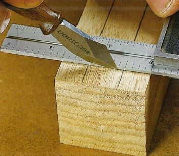
A sharp knife leaves the finest line, ensuring high marking accuracy. In some cases, the recessed line also becomes the starting position for the chisel
Fine-tuning of machines for precise machining of parts
Machines and power tools will only provide excellent results if they are properly set up and adjusted. This page shows the basic setup of three machines that are essential to most shops: a saw, a planer, and a router table. As you prepare them for work, remember the following rules.
- First of all, make the pieces of the same thickness. Start any project by cutting all pieces to the same thickness. Any differences in thickness make it difficult to obtain neat joints and require additional adjustment by sanding and scraping.
- A smart approach. Long boards are inconvenient to process, so it is better to immediately cut them into blanks with a small allowance, which are easier to handle, achieving the required accuracy.
- Double check the dimensions. The actual thickness of the slabs and sheet materials, as a rule, differs from the nominal value, so a caliper should be used to measure them. Only after this cut out the grooves, tongues and folds of the appropriate width.
Before sawing anything, check that the blade is parallel to the grooves in the table, set the crosscut (miter) fence to a 90° angle, and then set the rip fence parallel to the blade. At longitudinal sawing Use a clamping comb to hold the workpiece tightly against the rip fence.

Align the back table with the highest point of the trajectory cutting edges knives, as shown in the picture on the right. Then use a proven square to ensure that the rip fence is positioned exactly at right angles to the back table. To achieve excellent result When planing, always press the workpiece against the fence. Slowly feed the board onto the rotating cutter head. When the front end of the board passes over the blades, move the pressure point forward so that the board is pressed against the back table. To obtain a good result, adjust the back table and longitudinal fence.

Plan to complete most of your routing work in multiple passes, setting the fence to the final height or width for the last pass. Fix the position of the router after each change in the offset of the cutter. When removing grooves, tongues, folds and other joint elements, use clamps like the clamp comb shown here. It’s not difficult to make yourself, it doesn’t require a lot of material.

Final fit guarantees success
Regardless of how many joints you need to make on the machine, always make test runs and sample joints using scraps after each setting change. Adjustments should be continued until the test connection is tightly assembled, and only then can you begin processing the project details. But despite all your efforts, sometimes you can find imperfections in the connections. Sawdust on the saw table or unnoticeable warping of a previously planed piece can ruin the work and make assembly impossible. If the part is too thick or wide, resist the temptation to use machines to adjust the size. Precise fitting is best left to hand tools.
- Small zenzubel. With its help, it is possible to quickly remove a layer with a thickness of 0.5 mm or more from a wide spike or ridge. A zenzubel with a small angle of inclination of the piece is especially effective when working across the grain. The cutting edge protruding from the side allows you to process the inner corner close to the shoulder of the tenon.
- Rasp or file. A flat, coarsely cut rasp removes material quickly, but leaves a rougher surface than a plane. A flat file works slower, but it is good for smoothing the surface.
- Sandpaper. If you only need to remove a small amount of material from a tenon or other wide surface, apply a piece of 100-grit sandpaper to a suitable scrap board or block of cork. Use self-adhesive sandpaper or apply regular sandpaper using spray adhesive or double-sided tape. This method allows you to process only one plane without affecting adjacent ones, as happens if you simply wrap a block with sandpaper.
- Chisel. Blades of different widths will allow you to remove material from any hard-to-reach places. When sanding a flat surface, hold the chisel with the bevel facing up, pressing the flat front edge against the wood.
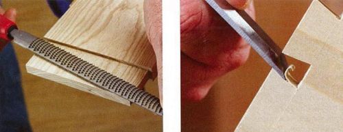
When using a rasp, chisel or any other tool to remove material, take your time and regularly check the result by connecting the parts.
Plan your assembly sequence carefully
You have carefully cut out all the parts, achieved tightness in all joints and are now ready to start assembling. But before you open the glue bottle, be sure to do a dry assembly test (without glue). When assembling the product, determine in what order it is best to connect the parts, how many clamps will be needed to tightly compress all the joints, and how best to place the clamps so that there are no distortions.
It is better to divide the assembly of large and complex projects into several simple steps, instead of fussing around trying to glue all the pieces together in one go. For example, when making a cabinet with paneled sides, first assemble the frames with panels, and then proceed with the main assembly. This approach gives you more time to check all connections and requires fewer clamps. Another way to gain time is to use glue with an extended setting time. For example, regular yellow Titebond glue allows you to complete the entire assembly in 15 minutes, and the Titebond Extend variety allows you to level the glue within 25 minutes.
When installing clamps, make sure that their pressure is applied to the middle of the connection. An incorrectly installed clamp can deform the parts so that a gap forms between them. Sometimes, despite all efforts, the connections do not turn out neat. An accidentally slipped tool, inattention, or undetected sawdust near the stop lead to a loose connection or a noticeable gap in it.

Assemble the cabinet in stages, first gluing together the small side panel frames. Then you can pay more attention to each connection. Then start assembling the case
How can you salvage a seemingly damaged work?
The gap can be sealed with a mixture of quick-setting epoxy glue and dust from sanding the same wood (the mixture should have the consistency of a thick paste). It is better to use epoxy glue instead of PVA, since the putty inevitably spreads over the surfaces adjacent to the joint and the epoxy glue hardens without being absorbed into the wood. Excess of this composition can be easily removed by sanding to avoid problems when applying the finish. Use this filling method when the appearance of the joint comes first, not its strength.

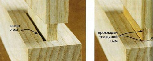
If, during trial assembly, the tenon dangles in the socket, such a connection will not be strong. Filling gaps with glue won't do any good, so take the time to reinforce a too thin part with wood. Saw out two overlays so that the tenon is slightly thicker than required, and glue them on both sides. After drying, adjust the tenon again to the size of the socket.
Turn a disadvantage into an advantage
Sometimes it is better not to hide traces of repair, but to make them visible. In a too narrow ash tenon, we made two cuts and inserted thin cherry wedges into them, which tightly pressed the narrow cheeks of the tenon to the edges of the nest. In other cases, such as when joining with a hidden tenon, small chamfers or roundings along the edges of the hanger will make the loose joint less noticeable.

Replace part
This can happen to any of us. Some errors do not make sense to correct for two reasons: (1) if, regardless of your skill and diligence, the unsightly defect will remain noticeable or (2) if it is faster and easier to make a new part to replace the damaged one.
The need to expand or lengthen a wooden workpiece is determined by the limited cross-sections and lengths of boards and beams available to the carpenter due to sawing trees.
There is also a need to connect two or more wooden blanks in a transverse or oblique direction when it is necessary to create a frame product using wood and other materials. Carpentry joints are made by gluing, using sockets and grooves that are connected to each other in the parts being connected.
These connections are called splices. They represent the connection of two or more wooden blanks with their plates or edges, respectively, resulting in a wooden product with dimensions that cannot be obtained from a whole piece of wood.
There are two different groups of docking connections
- joining two simply planed and glued parts with ends or edges;
- the second group of joints involves the presence of reinforcing elements, such as tenons or a tongue-and-groove connection.
Planar splicing, or butt joint along the length
Planar splicing is performed by gluing the straight edges of the boards. It is considered not very durable. The strength of such a connection is highly dependent on the thickness of the parts being joined, on the resulting contact between the surfaces of the parts being joined, as well as on the type of adhesive, which can easily change under the influence of atmospheric and thermal conditions.
Planar splicing in half a tree
When connecting two parts in half a tree, a groove is made in both parts of half the thickness so that when assembled, the groove of one part aligns exactly with the groove of the other. This type of connection allows you to get large area the joint surface is bonded with glue than in the previous case, and also allows for the possibility of strengthening the joint with screws or insertion tenons. It is used in the construction of decks and frame supports.
Widely used for joining board-shaped workpieces. Portable milling machines are used to make holes for plugs.
Zigzag splicing
The connection is very effective when it is necessary to prevent lateral displacement of the joint. To obtain such a connection, you need a moulding-planing machine and a cutter of the appropriate shape. The greater the inclination of the cut, the larger the surface to be glued, the higher the strength of such a connection.
A tsinubel planer with fine teeth on the cutting edge creates shallow grooves on the surfaces of the parts being joined. It is used for gluing large surfaces.
Planar splicing, or butt joint, reinforced with pins
A connection reinforced with wooden nails-pins inserted to the middle of the thickness of the wooden parts being connected. These studs can vary in design depending on the degree of connection needed to be achieved.
 |
 |
Figure 1. Alternating tongue and groove joint Figure 2. Tongue and groove joints with shaped tongues |
Tongue splicing
This joint is assembled using a tongue (or pin) and a groove (or groove), which is why it is called a tongue and groove joint.
In addition to processing solid pieces of wood, it is often necessary to connect wooden parts into units and structures. Connections between elements of wooden structures are called landings. Joints in the structures of wooden parts are determined by five types of fits: tense, tight, sliding, loose and very loose fit.
Nodes - these are parts of structures at the junction of parts. Wooden structure connections are divided into types: end, side, corner T-shaped, cross-shaped, corner L-shaped and box corner connections.
Joinery joints have more than 200 options. Here we consider only the connections that joiners and carpenters use in practice.
End connection (extension) - connection of parts along the length, when one element is a continuation of the other. Such connections are smooth, jagged with spikes. Additionally, they are secured with glue, screws, and overlays. Horizontal end connections withstand compressive, tensile and bending loads (Fig. 1 - 5). Lumber is increased in length, forming vertical and horizontal toothed joints (wedge lock) at the ends (Fig. 6). Such joints do not need to be under pressure during the entire gluing process, since there are significant frictional forces at work. Toothed connections of lumber made by milling meet the first class of accuracy.
Connections of wooden structures must be made carefully, in accordance with three accuracy classes. The first class is intended for high-quality measuring instruments, the second class - for furniture production products, and the third - for construction parts, agricultural implements and containers. The lateral connection by the edge of several boards or slats is called joining (Fig. 7). Such connections are used in the construction of floors, gates, carpentry doors, etc. Plank and slatted panels are additionally reinforced with crossbars and tips. When covering ceilings and walls, the upper boards overlap the lower ones by 1/5 - 1/4 of the width. The outer walls are sheathed with horizontally laid overlapping boards (Fig. 7, g). The upper board overlaps the lower one by 1/5 - 1/4 of the width, which ensures the removal of precipitation. Connecting the end of a part to the middle part of another forms a T-shaped connection of parts. Such connections have a large number of options, two of which are shown in Fig. 8. These connections (ties) are used when connecting the joists of floors and partitions with the piping of the house. Connecting parts at right or oblique angles is called a cross connection. This connection has one or two grooves (Fig. 3.9). Cross joints are used in roof and truss structures.
 |
| Rice. 1. End connections of beams that resist compression: a - with a direct half-wood overlay; b - with an oblique overlay (on the “mustache”); c - with a straight half-wood overlay with a joint at an obtuse angle; g - with an oblique overlay with a tenon joint. |
 |
| Rice. 2. End connections of beams (extension) that resist tension: a - in a straight overhead lock; b - c oblique patch lock; c - with a straight half-wood overlay with a joint in an oblique tenon (dovetail). |
 |
| Rice. 3. End connections of beams that resist bending: a - with a straight half-timber overlay with an oblique joint; b - with a straight half-timber overlay with a stepped joint; c - in an oblique overhead lock with wedges and a tenon joint. |
 |
| Rice. 4. Joining by cutting with reinforcement with wedges and bolts. |
 |
| Rice. 5. End connections of beams working in compression: a - end-to-end with a secret hollowed-out tenon; b - end-to-end with a hidden insert tenon; c - with a direct half-wood overlay (the connection can be strengthened with bolts); Mr. direct half-wood overlay secured with wire; d - with a straight half-wood overlay secured with metal clips (clamps); e - with an oblique overlay (on a “mustache”) secured with metal clips; g - with an oblique overlay and fastening with bolts; h - marking of the oblique overlay; and - end-to-end with a hidden tetrahedral tenon. |
 |
| Rice. 6. End extensions of the milling scheme during end gluing of workpieces: a - vertical (along the width of the part), toothed (wedge-shaped) connection; b - horizontal (according to the thickness of the part), toothed (wedge-shaped) connection; c - milling of a gear connection; d - sawing out a gear connection; d - milling of a gear connection; e - end connection and gluing. |
 |
| Rice. 7. Joining the boards: a - on a smooth reveal; b - on the insert rail; c - a quarter; g, e, f - in groove and tongue (with different shapes of groove and tongue); g - overlap; h - with a tip in a groove; and - with a quarter tip; k - with overlap. |
 |
| Rice. 8. T-shaped connections of bars: a - with a hidden oblique tenon (in the paw or in the dovetail); b - with a straight stepped overlay. |
 |
| Rice. 9. Cross connections of bars: a - with a direct half-wood overlay; b - with direct overlay of incomplete overlap; in - with fit in one nest |
Connections of two parts with ends at right angles are called corner connections. They have through and non-through tenons, open and in the dark, half-dark on the overlay, half-tree, etc. (Fig. 10). Corner joints (ties) are used in window blocks, in joints of greenhouse frames, etc. A tenon joint in the dark has a tenon length of at least half the width of the part being connected, and the depth of the groove is 2 - 3 mm greater than the length of the tenon. This is necessary so that the parts to be joined can easily mate with each other, and there is room in the tenon socket after gluing for excess glue. For door frames, a corner tenon joint is used in the dark, and to increase the size of the connected surface, a semi-dark joint is used. Double or triple tenons increase the strength of the corner joint. However, the strength of the connection is determined by the quality of its execution. IN furniture production A variety of corner box connections are widely used (Fig. 11). Of these, the simplest is an open end-to-end tenon connection. Before making such a connection, tenons are marked at one end of the board with an awl according to the drawing. By marking the side parts of the tenon, a cut is made with a fine-toothed file. Every second cut of the tenon is hollowed out with a chisel. To make the connection precise, first saw and hollow out the tenon sockets in one part. It is placed on the end of another part and crushed. Then they saw through, hollow out and connect the parts, cleaning the joint with a plane, as shown in Fig. eleven.
When connecting parts “mustache” (at an angle of 45°), the corner binding is secured with steel inserts, as shown in Fig. 12. At the same time, make sure that one half of the insert or fastener fits into one part, and the other half into another. A wedge-shaped steel plate or ring is placed in the milled grooves of the parts to be connected.
The corners of the frames and drawers are connected with a straight open through tenon joint (Fig. 3.13, a, b, c). With increased quality requirements (with outside the tenons are not visible) corner knitting is performed with an oblique connection in the dark, groove and tongue, or an oblique connection to the rail, as shown in Fig. 13, d, e, f, g and in Fig. 14.
A box-shaped structure with horizontal or vertical transverse elements (shelves, partitions) is connected using corner T-shaped joints shown in Fig. 15.
Corner notches are used to connect the elements of the upper chord of wooden trusses with the lower one. When connecting truss elements at an angle of 45° or less, one notch is made in the lower element (tightening) (Fig. 16.a), at an angle of more than 45° - two notches (Fig. 16.6). In both cases, the end cut (cut) is perpendicular to the direction of the acting forces.
Additionally, the units are secured with a bolt with a washer and a nut, or less often with staples. The log walls of a house (log house) made of horizontally laid logs in the corners are connected by a “claw” notch. It can be simple or with an additional spike (paw with a pit). The marking of the cut is carried out as follows: the end of the log is hewn into a square, to the length of the side of the square (along the log), so that after processing it turns out to be a cube. The sides of the cube are divided by 8 equal parts. Then 4/8 of the part is removed from one side from the bottom and top, and the remaining sides are done as shown in Fig. 17. To speed up the marking and accuracy of making cuts, templates are used.
 |
| Rice. 10. Corner end connections of workpieces at right angles: a - with a single opening through tenon; b - with a single through hidden tenon (in the dark); v-s single a dull (not through) thorn in the dark; g - with a single through semi-secret tenon (semi-dark); d - with a single blind spike in semi-darkness; e - with a triple open through tenon; g - in a straight half-tree overlay; h - through dovetail; and - into the eyes with trimming. |
 |
| Rice. 11. Box corner joints with straight through tenons: a - cutting out tenon grooves; b - marking the spikes with an awl; c - connection of a tenon with a groove; d - processing the corner joint with a planer. |
 |
| Rice. 12. Right angle corner end connections, reinforced metal inserts- buttons: a - 8-shaped insert; b- wedge-shaped plate; c- rings. |
 |
| Rice. 13. Box corner joints at right angles: a - straight open through tenons; b - oblique open through spikes; c - open through spikes in a dovetail; g - groove on the insert rail butt; d - in groove and tongue; e - on plug-in spikes; g - on dovetail spikes in semi-darkness. |
 |
| Rice. 14. Oblique (mustache) box joints at right angles: a - with oblique tenons in the dark; b - oblique connection to the plug-in rail; c - oblique connection to tenons in the dark; d - an oblique connection, reinforced with a triangular strip on glue. |
 |
| Rice. 15. Direct and oblique connections of workpieces: a - for a double connection in an oblique groove and ridge; b - on a straight groove and ridge; c - on a triangular groove and ridge; d - on a straight groove and a ridge in the dark; d - for straight through tenons; e - on round inserted tenons in the dark; g - on a dovetail spike; h - on the groove and ridge, reinforced with nails. |
 |
| Rice. 16. Nodes in truss elements. |
 |
| Rice. 17. Interfacing the logs of the log house walls: a - a simple paw; b - paw with a wind spike; c - marking of the paw; 1 - wind spike (pit) |
Chiseling and cutting wood
The simplest connection of wooden parts involves a tenon and a socket. Sockets for spikes, as well as eyes, are made by chiselling along the markings. For chiselling, a chisel and chisels are used. Rectangular sockets are hollowed out with chisels, and sockets in narrow and thin parts are selected with chisels, tenons and sockets are cleaned, joints are adjusted, and chamfers are cut. In addition, chisels are used to process curved surfaces in cases where this cannot be done with another tool, such as a plane.
Chisels (Fig. 1) are used for carpentry and carpentry. The handles of the chisels are made from dry hardwood: beech, hornbeam, maple, ash, etc. The tool must be sharpened; chipping on the blade is not allowed. In the case of a through socket, the workpiece is marked on both sides (Fig. 2, a), in the case of a non-through socket, on one side (Fig. 2, b). The through nest is first selected from one side of the workpiece, then from the other.
The chisel is selected according to the width of the socket. For convenience, identical sockets are sometimes selected simultaneously in several stacked parts. The chisel for work is placed with a chamfer inside the socket, retreating from the marking line by 1...2 mm (Fig. 2, c). This is necessary to clean out the nest with a chisel. During operation, the chisel is held perpendicular. The first blow on a chisel placed across the fibers cuts the fibers, and the second blow on a chisel placed inside the socket separates the chips (Fig. 2, d).
 |
| Rice. 1. Chisel: a - carpenter’s chisel (blade width - 16, 20, 25 mm); b - carpentry (blade width - 6, 8, 10, 12, 16, 20 mm). |
 |
| Rice. 2. Chiseling sockets with a chisel: a - through socket; b - non-through socket; c - position of the bit; g - chiselling technique. |
 |
| Rice. 3. Mallets: a - round; b - prismatic. |
 |
| Rice. 4. Using a stop when chiselling: 1 - clamp; 2 - detail; 3 - metal stop; 4 - chisel. |
 |
| Rice. 5. Chisels: a - flat (blade width - 4, 6, 8, 10, 12, 16, 20, 25, 32, 40, 50 mm); b - semicircular (blade width - 4, 6, 8, 10, 12, 16, 20, 25, 32, 40 mm). |
The shavings must be trimmed to the full depth of the nest - to the cut fibers, otherwise you will not get a nest with smooth edges. When chiseling the eyes, when the sides of the socket are filed, undercutting is performed, i.e., the corners of the eye are trimmed for subsequent finishing chiselling.
Mallets, which are used to strike the tool during chiselling, can be round or prismatic (Fig. 3). The material for mallets is elm, hornbeam, and viburnum wood.
When chiselling a hole in a thick workpiece, it is recommended to use a stop (Fig. 4), which is a metal strip 1 - 1.5 mm thick, curved at an angle of 90°. This emphasis is secured to the timber with a clamp. To avoid damaging the surface of the part when clamping, it is necessary to place a gasket under the strip.
Using chisels (Fig. 5), sockets, edges, grooves and chamfers are processed. Curvilinear surfaces are treated with semicircular chisels, all others with flat ones. The sharpening angle of chisels is 25°.
Techniques for working with a chisel are shown in Fig. 6. When cutting with a chisel, use your left hand to adjust the thickness of the chips being removed and the direction of cutting, and advance the chisel with your right hand. In thin parts, sockets and eyes are hollowed out with chisels using a mallet; in all other cases, hand pressure is used.
Since the tool has a sharp cutting part, any loss of attention during work inevitably leads to injury, so when working with a chisel you need extreme care and knowledge of the basic rules for using it. It is forbidden to cut with a chisel towards yourself, with the part resting on the chest, with the part placed on the knees, in weight and in the direction of the supporting hand.
There are forged chisels on sale, which have the best cutting properties, and stamped ones. Semicircular chisels with a small width of the cutting part, as well as cranberry chisels, are usually made by the craftsmen themselves. They are used for selecting wood in round nests when performing simple carving work. Such chisels are also found in wood carving tool sets.
To work, a carpenter only needs two chisels with a blade 6 and 12 mm wide, as well as a set of chisels with a blade width from 2 to 16 and 25, 40 mm.
A cutter cutting wood encounters resistance from it. The amount of resistance that the cutter encounters over an area of 1 m2 of cross-section of the chip is called specific cutting resistance. When cutting wood, the angles formed by the front and rear edges of the cutter with the processing surface are distinguished (Fig. 8).
The angle between the front and rear edges of the cutter is called the sharpening angle. For planing knives and chisel it is 20...30° and depends on the hardness of the material being processed.
The angle between the front edge of the cutter and the cutting surface is called the cutting angle. For planing knives of hand tools it is 45...50°, and for machine tools - 45...65°. The cleanliness of the surface treatment depends on the cutting angle - the larger it is, the smoother the surface. Increasing the cutting angle increases the cutting force. The surface finish depends on the tool rotation speed and material feed. In other words, the higher the tool rotation speed and the lower the feed speed, the higher the surface finish. The angle between the back edge of the cutter and the cutting surface is called the clearance angle. The magnitude of this angle depends on the sharpening angle and the cutting angle.
There are three main cutting options (Fig. 9): across the grain, along the grain and cutting to the end. End cutting requires the most effort. Cutting obliquely (at an angle to the direction of the grain) is performed on cross-grained or twisted wood. Cutting along the grain is 2…2.5 times less than cutting across the grain.
The cutting force depends not only on the sharpening angle and the cutting angle, but also on the hardness of the wood, the width of the cutter blade, the moisture content of the wood, the cutting direction, the sharpening of the cutter and the friction forces against sawdust and shavings.
Hard wood (oak, beech, ash, pear, etc.), as well as wood that has knots, curls, and cross-grained wood, requires a lot of effort when processed. The heterogeneity of the wood structure determines the unequal resistance value, depending on the cutting direction.
The shape of the chip depends on the cutting direction. When cutting to the end, the chips will appear in the form of sawdust. When cutting along the grain, ribbon-like chips are formed. When cutting wood across the grain, chips are obtained in the form of small chips, and the treated surface becomes rough.
Dulling of the cutter requires an increase in cutting force. A dull cutter does not cut, but presses and tears the wood. Due to the dullness of the cutter after 4 hours of work, the cutting force increases by 1.5 times. A dull cutter increases friction between the cutter and the chip, requiring additional effort and overheating of the cutter.
Wet wood is easier to process than dry wood due to the latter's hardness. However, the cleanliness of processing wet wood is lower due to hairiness.
The cleanliness of wood processing depends on the cutting direction. Cutting along the grain produces a smooth surface. When cutting across the grain, clean cutting is possible with a sharp cutter and very thin chips. The cutter processing the wood goes deep into it, the chips, due to elasticity, are separated before the cutter touches, and the processed surface has a roughness. This is typical when cutting across the die (Fig. 10, a). To obtain a clean surface finish, a support ruler is placed in front of the cutter. A clean surface can be obtained if the cutter of a planing tool (manual, electrified or machine-made) is supplemented with a chip breaker (Fig. 10, c, d). It increases the cutting angle, breaks the chip, turning it into a spiral. The thinner the chip thickness, the better cleanliness surface treatment.
 |
| Rice. 9. Cutting wood: a - cutter in open cutting; b - cutter in closed cutting; c - cutting directions; 1 - across the fibers - to the end; 2 - along the fibers; 3 - in the tangential direction; 4 - in the transverse end direction; 5 - in the longitudinal-end direction; 6 - in the longitudinal-transverse direction. |
 |
| Rice. 10. Cutting techniques: a - chipping chips before cutting them; b - cutting with a supporting ruler; c - use of a chip breaker; d - with increasing cutting angle. |
Increasing the cutters (teeth of a circular saw, knives on the shaft of a planer, etc.) reduces the thickness of the chips and increases the cleanliness of processing. The quality of processing of wood of any species, including the presence of defects (knots, cross-layers, curling, etc.), is affected by the speed of movement incisor With increasing rotation speed cutting tool The waviness of chip formation becomes finer, which increases the cleanliness of the machined surface. The cleanliness of processing of individual areas is affected by defects, properties of wood, sharpness of cutters, inaccuracy in marking, violation of technology. Deformations of wood caused by its moisture content exceed the dimensional deviations permissible in woodworking. Before processing lumber for carpentry and joinery parts, the moisture content of the wood is checked.
Additional fastenings for joinery joints
Wooden structures become deformed during use and their connections become unstable. In such cases, the joints are secured with wooden dowels, tenons (dowels), wedges and dowels (Fig. 1) made of very hard and dry wood (humidity 4 - 6%).
Wooden nails (pins) made from oak, maple, ash or birch. Before driving the dowel, drill a hole (through or non-through) of the required diameter and round the edges of the dowel. This protects the wood from cracking at the joints (in the corners of window and greenhouse frames, etc.). Wooden dowels, for example, secure rafter joints to the roof ridge. They are cylindrical, rectangular and square. The lower end of the spike is made somewhat pointed. Before driving the tenon, a hole is drilled with a slightly smaller diameter than the diameter of the tenon. Wooden wedges are made from wood coniferous species(pine, spruce), single or double sided. One-sided wedges have one wide side cut obliquely, while double-sided wedges have both sides cut obliquely. The sides have a slope of 1:6, 1:7 and 1:8°. These wedges are used to strengthen and tension wooden structures, level floor joists, and raise sagging parts of walls and roofs. Wedges are used to jam the handles of hand tools (axes and hammers), although preference should be given to metal wedges.
Dowels.
Composite beams made of two or three beams with wooden dowels. The shearing forces between them are absorbed by the dowels. The beam elements are additionally tightened together with steel bolts. Oak dowels are inserted into the slots between the elements of the composite beam. The slots for the keys are selected using an electric shaper simultaneously in two beams, then the keys are driven into the slots with blows wooden hammer. The protruding ends of the keys are cleaned with a plane. Due to the low load, dowels are not installed in the middle of the span of composite beams.
In relation to the elements being connected, dowels are distinguished: longitudinal, transverse, oblique longitudinal and dowels with tension (Fig. 2). Transverse dowels (compared to longitudinal ones) provide a less durable connection, since wood across the grain has less resistance than along the grain.
Composite beams with dowels are made from well-dried wood. If the key is installed in a slot with a gap, then it will not perceive shear forces and the transmitted load will be transferred to other keys. Mechanized production of keys and sockets guarantees the appearance of gaps. The cross section of composite beams should not be weakened by nests by more than 1/3 of the height of the element. If the nests are symmetrically located on opposite sides, their depth should not exceed more than 1/6 of the thickness of the element, but not less than 2 cm. Longitudinal dowels and bolts are used to connect the beams (Fig. 2, e). A strong and tight connection is obtained by using two wedge-shaped keys with tension (Fig. 2d), acting as wedges. The advantage of such keys is that during operation the wedges can restore the tension. Dowel joints are used to strengthen floor beams and Derevyagin beams (Fig. 3).
 |
| Rice. 1. Installation of insert tenons: a - installation of a cylindrical wooden pin (dowel) on glue; b - tense corner connection on two cylindrical spikes; c - tense corner connection on three rectangular wooden tenons. |
 |
| Rice. 2. Tightening with bolts two beams connected by keys: a - longitudinal keys; 5 - transverse keys; h - transverse keys located diagonally; g - wedge-shaped keys; d - with bolts passed through the keys. |
 |
| Fig 3. Composite beam of the Derevyagin structure: a - front view and cross section; b - fragment of the location of keys in a composite beam. |
Making shields from wood
To minimize or prevent warping of panels intended for the manufacture of furniture and other purposes, the following measures are taken: for the manufacture of panels, only dry wood is used (humidity - 8-10%); wide boards are sawn into narrower ones, and panels are made with a width of no more than 100 mm; adjacent sections in the panels are positioned so that the annual layers at the ends of the welded blanks are at different angles when connected (it is better if they are directed in opposite directions).
To reduce warping of solid wood panels, constructive measures are also used (Fig. 1): joining on dowels with tips and tying the panels with a frame with grooves. The best effect is achieved by tying the panels with a frame.
Solid wood shields are knitted using combs, dovetail spikes and inserted round spikes. The easiest method for marking and execution is knitting on a comb. The dimensions of the spikes are equal to the dimensions of the eyes of the socket. Dovetail knitting is used mainly in the manufacture of boxes, caskets, etc. It is complex both in marking and in manufacturing.
T-joint joinery of carpentry panels is widespread (Fig. 2). It is performed mainly in groove and tongue. In this case, the edges are carefully processed, since their precise fit is required. The grooves are made by joining manually; their depth is from 1/3 to 1/2 of the thickness of the shield. The easiest to perform is the connection in a wide groove. The use of shoulders increases the stability of the knit. The greatest rigidity of the structure will be when connecting the rewards with two shoulders. It is performed mainly without the use of glue. It should be noted that the reward method is used only for knitting solid wood shields.
In addition to the main methods of tying into knots, parts are also connected with nails, screws and bolts, using metal and wooden squares and an additional bar (Fig. 3).
The wedge-tenon joint with glue is considered very durable. How to make such a connection is shown in Fig. 4. When the spike with the wedge inserted into it reaches the bottom of the socket, it will wedge and be firmly held in the socket. The wedge can be made from durable and dry wood (oak, beech, etc.).
How to drive a nail correctly: First, mark the points and prick them with an awl, watching the angle of the awl as the nail will go in the direction of the prick. If possible, nail the nail not perpendicular to the plane, but at a slight angle. This will make the connection more reliable. If a nail is nailed perpendicular to the plane, it will serve as an axis of rotation and the connection will soon weaken. It is necessary to nail a thin part to a thick one. The diameter of the nail should be no more than 1/4 of the thickness of the part being pierced, and its length should be 2...4 times greater than this thickness. When punching the parts to be joined, bend the tip of the nail. To do this, press the triangular file tightly against it and bend the hook with a hammer on the end of the nail. After removing the file, drive the hook into the wood.
To prevent the board from splitting when driving a nail, dull the tip (or bite it off with wire cutters). Such a nail will crush the wood fibers, but will not split it.
 |
| Rice. 1. : a - joining on a key; b - frame with groove; 1 - shield; 2 - socket; 3 - key; 4 - frame with groove; 5 - comb. |
 |
| Rice. 2. : a - in a wide groove; b- in a narrow groove with one shoulder; c - into a narrow groove with two shoulders; g - award with one shoulder; d - reward with two shoulders; e - rewarded with flat spikes; g - rewarded with inserted round spikes. |
 |
| Rice. 3. : a - metal square; b - plywood square; c - a wooden block; g - with a coupling bolt. |
 |
| Rice. 4. : 1 - socket; 2 - wedge; 3 - thorn. |
When nailing joinery pieces together, remember that a nail driven along the grain has a weaker hold than a nail driven across it. Some hammered nails, located close to each other along one layer, can split the board. This will also happen if a thick nail is driven close to the edge. Therefore, to ensure a strong connection, hammer in several not very thick nails in two rows, placing them in a checkerboard pattern. If, based on the design of the part, you need to hammer a nail at the edge of the edge, then pre-drill a hole for it. The diameter of the hole in this case should be 1/5 - 1/7 less than the diameter of the nail.
To under the right angle hammer a nail, especially a small one, stick a piece of plasticine or wax on the place where it should be hammered and stick the nail into it at this angle. After one or two blows with a hammer, the plasticine can be removed.
When nailing a board, drive the nails not parallel to each other, but at a certain angle, with each of them at different sides. In this case, the fastening will be more reliable.
You can drive a nail into a hard-to-reach place using a metal tube and a rod that fits freely into this tube. To do this, place the tube in the place where the nail should be driven in, lower the nail into it, then the rod and hit the rod several times with a hammer. The nail will go into the wood, but unevenly. Having removed the rod, use a tube to align the position of the nail and then hammer it in using the “nail - rod - hammer” system. The rod should be 10-15 mm longer than the tube.
If the screw connecting the parts is loose and turns when screwed in, it can be strengthened by first inserting a match into the socket; The screw itself must be lubricated with Vaseline. It is difficult to drive a screw into chipboard. But you can do this without much effort if you first drill a hole with an electric drill. Fill this hole with glue, place a piece of soft plastic tube in it and screw in the screw. The glue that has penetrated inside the tube will facilitate the screwing process; Once it dries, it will firmly hold the tube and screw in the socket.
When unscrewing a “stubborn” screw, lightly tap the handle of a screwdriver inserted into its slot with a hammer. In this case, the screwdriver must be turned with a certain force.
To properly screw a screw into hard wood, use an awl to prick the screwed area and sprinkle some soap crumbs there; the screw will screw in easier. Also, when screwing in a thick screw, drill a hole with a diameter 1/5 smaller than the diameter of the screw; The depth of the hole must be greater than the length of the screw. When the screw diameter is 2 mm or less, there is no need to drill: it is enough to make a puncture with a sharp object (an awl, a scriber, etc.).
How to choose a wooden blank
Wooden blanks, popularly called “linen,” come in many different shapes and sizes. They are made mainly from available cheap wood species - linden, birch, aspen. The main rule when choosing a workpiece is the quality of the material and assembly (for glued products). Wood for workpieces (except for solid turned pieces) must be seasoned - dried, so that after processing and drying the wood does not “lead”, it does not crack or dry out, and there should also be no visible severe damage, pronounced burrs, burrs and through holes from knots . The surface should be smooth, not loose or porous.
The quality of assembly of glued blanks (boxes, icon boards, complex shapes) affects how the product behaves after processing. If the arrangement of the layers is incorrectly selected and the parts are poorly fitted, then cracks may appear at the joints. Do not expect that the crooked box will then “dry” and straighten out, as unscrupulous sellers promise, rather the opposite.
To make jewelry you need wooden buttons, beads, and bracelets. For painting, decoupage and decoration - frames, plates, trays, spoons, nesting dolls, dolls, glass holders, cutting boards, boxes, dishes, vases, caskets, mugs, whistles, toys. For icon painting, ordinary boards are not suitable; special ones are needed - icon boards, with special inserts to prevent warping.
For carving “Trekhgranka”, “Kudrinka”, “Tatyanka” all linden blanks are suitable (birch and aspen are more difficult to process with cutters) without knots with a wall thickness of 7-10 mm for low relief and 10-15 mm for high relief. And it’s better if the workpiece is made from wood from 2-3 year old trees, because its structure is more homogeneous and dense. There are blanks only for carving, these are gingerbread boards and Easter molds.
For light decoupage and lightly tinted carvings, the blanks must be without darkening. For painting and decoration, blanks with darkening are primed, so dark knots and “marble” coloring of the wood will not interfere, as well as shallow dents that can be hidden - before priming, they are filled with a mixture of sawdust and PVA (in several layers with intermediate drying) or papier mixture -mache (it is better to make the mass from pieces of napkins with glue). In the same way, you can correct a defect in collapsible turned shapes (matryoshka dolls, apples, eggs, pears) when the upper part does not sit tightly and falls off when turned over - to do this, you need to coat the inner edge of the upper half with the mixture and dry it well (if you do it on the lower half, it will be noticeable and ugly). If the hollow collapsible “point” has dried unevenly and does not close, then grind top part from the inside and the outer border of the bottom.
Before processing, the workpieces should be stored tightly closed. plastic bag to maintain their stabilized humidity and prevent drying, warping or dampness.
Saws and Sawing
Saws and sawing. Saws are made from high quality steel with cut teeth. For carpentry and joinery work, use a wide hacksaw, a hacksaw with a butt, or a narrow hacksaw; a saw with a cutting depth limiter (reward), a bow saw, and also a plywood file (knife) (Fig. 1).
A wide hacksaw is made from a steel strip 0.7 m long, 11 cm wide at the handle and 2...7 cm at the narrow end. The handle can be wooden, metal or plastic. A narrow hacksaw is used for cutting curved through holes in large-width parts. The jigsaw (Fig. 2) has a narrow and thin (0.3 mm thick, 1...2 mm wide) file with fine teeth. The file is fixed in an arched frame and can be easily removed. Thin parts (plywood) of a curved shape are cut out with a jigsaw. Before starting work, the end of the file is inserted into a pre-made hole, and the other end is secured in the frame. Sawing is carried out according to the markings. At the end of the work, release the end of the file and remove it from the hole in the part.
Hacksaws with a back are used for shallow sawing, for example, sawing grooves in wide workpieces, for fitting parts during their assembly. The top of the canvas is reinforced with a steel backing, which increases the rigidity of the canvas. The fine teeth have the shape of an isosceles triangle. Use a hacksaw to cut in both directions (Fig. 1, c).
Based on the shape of the teeth, saws for longitudinal, mixed and cross-cutting are distinguished (Fig. 3).
For sawing along the grain, saws with oblique teeth are used. They cut wood in one direction - away from themselves. The cavity between the teeth is called the sinus. The tooth pitch is the distance between the tips of adjacent teeth. The height of a tooth is equal to a perpendicular drawn from the top of the tooth to its base. There are three edges in the saw tooth (Fig. 3, a). In rip saws, the cutting is performed by a short cutting part - the front edge, and the side edge only separates the wood fibers.
 |
|
| Rice. 1. : a - wide hacksaw: b - the same, narrow; c - axing hacksaw; g - reward; d - plywood saw. | |
 |
 |
| Rice. 2. Jigsaw. | Rice. 3. : a - saw elements; b - saw tooth angles; I - for longitudinal sawing; II - for mixed sawing; III - for cross cutting: 1 - side cutting edges; 2 - front edge; 3 - front cutting edge; 4 - step; 5 - top; 6 - sinus; 7 - height; 8 - line of the base of the teeth. |
A bow saw is used for longitudinal and cross cutting. It consists of a beam frame with a tensioned saw blade. The latter is made of steel strip about 1 m long, 45...60 wide and 0.4...0.7 mm thick. The pitch of the teeth is 4...5 mm, the height of the teeth is 5...6 mm. The ends of the saw blade are fixed at the bottom of the beam frame posts. The canvas is stretched with a string of twine secured between the upper ends of the posts and twists. The saw blade is rotated using handles. This saw can be operated by one person. The cut is smooth and even. The teeth of crosscut saws cut the fibers, the side edges of the teeth, and the leading edge only separates them. In rip saws, the leading edge of the tooth cuts the wood. This is taken into account when determining the sharpening angles of saw teeth for transverse and longitudinal sawing.
 |
||
| Rice. 4. Sawing along the grain with a bow saw, if the material is in a horizontal position: to the right - the position of the worker’s feet during sawing. | ||
 |
 |
 |
|
Rice. 5. Stands: a - wooden with a movable support: b - metal with a roller; c - wooden with a roller. |
Rice. 6. Sawing with a bow saw along the grain while securing the material vertically: a - the position of the worker’s hands during sawing; b - the same, feet. |
Rice. 7. Cross cutting: a - sawing techniques; b - supporting the sawn part with your hand at the end of sawing. |
In saws for longitudinal sawing of soft wood, the sharpening angle is 40...45°, in saws for hard wood - up to 70°, in cross-cut saws, the angle between the cutting edges of the teeth is 60...70°, and the sharpening angle is 45... 80°. Saws for mixed sawing have a sharpening angle of 50… 60°. The angles of the saw teeth are as follows: for longitudinal sawing - 60...80°, for transverse sawing - 90 -120°, for mixed - 90°. For sawing shallow grooves and sockets of tenon joints, the so-called reward is used. To regulate the cutting depth, it has a movable stop. Saw blade thickness 0.4…0.7 mm, length -100…120 mm.
Types and techniques of sawing. According to the type of fastening of the part in the workbench, they are distinguished: horizontal sawing along the grain, vertical sawing along the grain, horizontal sawing across the grain and sawing at an angle. When sawing horizontally along the grain, the workpiece is secured by pressing it against the table with clamps (Fig. 4) so that the sawn part protrudes beyond the edge of the workbench. In this case, the worker’s body should be slightly tilted forward, and the saw should be held vertically. First, they make a cut, moving the saw up several times, after the cut becomes deep, they begin sawing, moving the saw up and down. A wedge inserted into the cut prevents the saw blade from jamming.
When vertical sawing along the grain, the workpiece is secured in the workbench with a front or rear clamp (Fig. 6). The figure shows the position of the worker's legs during the sawing process. When sawing a thin board, it is clamped so that it does not bend, lifting it upward as it is sawed. Sawing begins with a cut, after which they work to the full swing of the saw blade, without pressing on it. Short workpieces are sawed starting from one end, and then, turning the workpiece over, from the other. Sawing long boards (along the grain) is carried out by resting their ends on stands (see Fig. 5).
 |
| Rice. 8. : a - correct; b - incorrect (cutting angle is too large); c - splintered cut, due to improper sawing, flakes and damage to the edges are possible; g - sawing along the fibers with a hacksaw; d - sawing with a bow saw using a template (miter box); e - sawing with a narrow hacksaw through drilled holes; g - template for trimming the ends of boards placed in bags; 1 and 2 - side posts - guides for the saw; 3 - board attached to the racks; 4 - fastening nail of the auxiliary device; detail A - the position of the hand on the frame of the bow saw during sawing. |
When sawing the workpiece across the grain, the sawn end is pushed beyond the edge of the workbench (Fig. 7). Before starting sawing, make a gash; during the sawing process, monitor the position and inclination of the saw blade and ensure that the cut is straight and the sawn surface is flat.
To avoid flakes, the sawn part of the workpiece (Fig. 7, b) should be supported by hand at the end of sawing. For tenon joints or other parts that require mating at an angle of 45 or 90°, use a template (miter box) (Fig. 8, e). With repeated use, the cuts on the wall of the miter box may become excessively wide and it will not give the exact size of the angle. To extend the durability of the miter box, its side walls are made of hardwood boards. To trim boards (one width), use a special template (Fig. 8, jar). Side racks The templates serve as guides for the saw; they are made of hard wood. For boards of a certain width, a custom template is required. Sawing wood by hand is acceptable for small volumes of work.
Preparing the saw for work
Preparing the saw includes jointing, setting and sharpening the teeth. The nature of the saw's operation is influenced by the shape, size and inclination of the teeth. Saws with isosceles-shaped teeth are recommended to be used only for cross-cutting, rectangular-shaped - for longitudinal and transverse sawing, with inclined teeth - only for longitudinal sawing.
Planing saw (Fig. 1) consists of aligning the tops of the teeth so that they are at the same height. To do this, a file is secured in a vice and the tips of the teeth are moved along it. The quality of jointing is checked by applying a ruler to the tops; in this case, there should be no gaps between the tops of the teeth and the edges of the ruler.
Setting . To prevent the saw blade from getting pinched in the cut, the saw teeth are set apart, that is, they are bent: even teeth in one direction, odd teeth in the other. In this case, not the entire tooth is bent, but only its upper part (1/3 from the top of the tooth). When spreading the teeth, it is necessary to maintain the symmetry of the bends on both sides. For sawing hardwood, the teeth are set apart by 0.25...0.5 mm on each side, and for softwood - by 0.5...0.7 mm.
 |
 |
| Rice. 2. Universal wiring: 1 - plate; 2 - adjusting screws; 3 - scale showing the size of the divorce; 4 - a screw with a stop that regulates the height of the tooth being bent; 5 - spring; 6 - lever for bending the tooth away from the saw. | Rice. 3. Template for checking the correct alignment of the saw teeth: 1 - saw; 2 - template. |
When sawing raw wood the spread should be maximum, and dry should be 1.5 times the thickness of the saw blade. The width of the cut should not be more than double the thickness of the blade.
To set the saw apart, a novice carpenter is recommended to use a special set (Fig. 2). The correct alignment of the saw is checked with a template (Fig. 3), moving it along the blade. The saw is moved evenly, without using much force, as otherwise you can break the tooth.

The teeth are sharpened with diamond- or triangle-shaped files, with double or single notches. Before sharpening, the saw is securely secured in a vice on the workbench. The file is pressed against the tooth while moving away from you; when returning it, lift it slightly so that it does not touch the saw. You should not press the file tightly against the tooth, as this will heat up the file, which will lead to a decrease in the strength of the teeth.
The teeth of saws for longitudinal cutting are sharpened on one side and the file is held perpendicular to the blade. For cross cutting, the teeth are sharpened through one and the file is held at an angle of 60...70°. Bow saws are sharpened with a triangular file.
Saws with large teeth are set and sharpened, while saws with small teeth are sharpened, but not set. This is explained by the fact that in carpentry work they use completely dry material, the blade of bow saws is thin (0.5... 0.8 mm), the dimensions of the cut along the length are not particularly large, so the danger of clamping is almost eliminated, and small teeth with a pitch of 2... 3 mm is very difficult to spread. The cleanliness of sharpened but not set saws with a tensioned blade is much higher than that of one-handed hacksaws with a set blade, which is especially important when sawing tenons and eyes.
Working with a bow saw
To operate a bow saw, the blade must be positioned correctly in relation to the machine. Its tilt angle should be 30°; Correct rotation is adjusted using a knob. The saw blade should be straight, without distortion and well tensioned. They saw slowly, but with confident movements; If you rush, the cut will turn out uneven.
On a high-quality bow saw in working condition, turning the handles should be difficult. After work, it is recommended to loosen the screw so as not to expose the stand to stress and not to stretch the canvas.
When ripping, the material to be cut must hang outward. When cutting crosswise (Fig. 1, a), the workpiece lies horizontally; when sawing longitudinally (Fig. 1, b), it can be in horizontal and vertical positions. Usually they start cutting from the nail thumb left hand (Fig. 2), which is why this technique is called “by the nail.” When sawing, the marking mark must be visible at all times. For precise cross cutting of boards, a miter box (shtosslad) is used, which is a box with cuts in the side walls made at a certain angle (Fig. 3).
 |
|
| Rice. 1. Cut the boards with a bow saw: a - transverse; b - longitudinal. | |
|
|
| Sawing along the grain with a bow saw, if the material is in a horizontal position: to the right - the position of the worker’s feet during sawing |
For sawing wood with cross-layers, knots and other defects, a bow saw with a thicker and wider (up to 50 mm) blade is used. A circular saw, which has a narrow blade (up to 8 mm), rectangular teeth and a large set (2 - 2.5 thickness blades), as well as high machine stands, you can perform curved sawing, since a large spread of the blade gives a wide cut, in which the blade can easily be turned in the required direction.
When sharpening a bow saw secured in a vice, the file may slip and injure your hand. And holding your hand on the sharp edge of the file is not very comfortable. To insure yourself against possible injury, place a tip made of a rubber tube (length 3...4 cm) cut along the length on one side onto the file head.
After purchasing a bow saw, carpenters sometimes shorten the mullion, change the string, make wider bow stands, since shortened machines are convenient to use, wider stands reduce their deflection when tensioning the bowstring, and with a bowstring thickness of 10 mm, an even and strong tension is obtained and it is eliminated gap The string in the places where it adjoins the posts is usually wrapped with fishing line at a distance of 25...30 mm from the posts. At the same time, if the twist breaks, the bowstring does not fall off the machine.
For convenience, additionally clean the handles in the bow saw with fine-grained sandpaper and coat the entire machine with oil varnish.
To tension a bow saw, it is advisable to use a lever bowstring instead of a twisting one (Fig. 4). Such a bowstring can be easily made from two pieces of cable with a diameter of 2...3 mm. The device uses a metal lever, the end of which is bent and inserted into the hole in the mullion. The degree of tension depends on the position of the hole into which the lever fits. It takes seconds to loosen or tighten the tension on the saw blade. In addition, the cable is an “eternal” bowstring. The mullion can be made of wood, for which you need to choose a hard species (for example, beech).
To reduce friction of the bow saw blade against the walls of the cut, its thickness should be reduced. To do this, attach the canvas horizontally with a clamp to a metal base. At a distance 4...1 times the width of the blade, fasten a metal plate on the base with a thickness 5 times the thickness of the saw (Fig. 5). Then, using a coarse file, resting its end on a metal plate, remove the layer of metal from the saw. Do the same operation on the other side of the saw. After removing the metal, sand the blade with fine-grit sandpaper.
 |
|
| Rice. 4. Tension device for bow saw: 1 - stand; 2 - cable; 3 - lever; 4 - middle. | |
 |
|
| Rice. 5. Reducing the thickness of the bow saw: 1 - saw blade; 2 - metal base; 3 - plate placed to form a thinning angle; 4 - file; 5 - clamp. |
Modern bow saw It is a metal tube (or rod) bent by an arc, between the ends of which a cutting blade is stretched. A rigid arc allows you to make the cutting blade thin, long, and narrow. Depending on the size of the arc, a blade with a large tooth (4 - 5 mm high) can be from 30 to 90 cm long. The cutting blade is attached using bolts, pins or an eccentric bracket, which makes it easy to adjust the degree of its tension.

The cutting blade of some bow saws is secured using rotary couplings. They make it possible to rotate the plane of the blade relative to the plane of the saw itself. At the beginning of the cut, the saw should be held so firmly that the force of the hand is significantly greater than the weight of the saw. The hand gets tired quickly, but the cut will be smooth.
Another simple rule: the teeth of a bow saw should cut into the wood due to the weight of the saw itself. If you try to apply force, the thin and narrow cutting blade will begin to “play”, which will greatly complicate the process itself. All bow saws whose arc is made from a metal tube have plastic, metal or wooden handles of different configurations and are intended only for direct hand operation.
Lumber marking
The wood is marked so that as little waste as possible is generated from the lumber used for blanks for parts. In other words, marking is necessary to obtain a workpiece with a minimum allowance for processing with manual or electrified tools. To mark and check the accuracy of processing workpieces and parts, many special and universal devices are used. For a novice carpenter, at the first stages of mastering carpentry skills, the following tool is needed (Fig. 1):
- 5 meter tape measure - for linear measurements and rough marking of lumber;
- square - to check the angle of 90°;
- folding meter - for any measurements of width and thickness;
- malka - for measuring and measuring angles; level - to check the horizontal and vertical arrangement of surfaces;
- compass - for transferring dimensions to workpieces and for marking circles;
- thicknesser - for applying marks parallel to one of the sides of the bar or part;
- plumb line - to check the verticality of wooden structures.
Marking lines are applied with a pencil, and on a clean planed surface with an awl. On boards and other long materials, lines are drawn with a cord-beat, and on light parts they should be beaten with charcoal, on dark parts - with chalk.
 |
| Rice. 1. 1 - tape measure, 2 - square; 3 - folding meter; 4 - fry; 5 - level; 6 - compass; 7 - surface planer; 8 - plumb line; 9 - awl. |
 |
| Rice. 2. a - for marking spikes; b - for dovetail markings; 1 - scriber; 2 - workpiece; 3 - template. |
 |
| Rice. 3. 1 - handle; 2 - roulette; 3 - window for setting the required radius; 4 - body; 5 - scriber (knife); 6 - clamping bar; 7 - fastening screw; 8 - installation needle. |
It is recommended to apply marking lines with a simple pencil of hardness T or TM. Colored pencils have a soft lead and break quickly; Lines drawn with a chemical pencil inevitably blur when the surface is wetted, resulting in contamination of the material.
The division scale on a metal ruler often wears off. To avoid this, paint the ruler canvas treated with acetone with white or red nitro paint, then wipe the ruler with a cloth. The paint will be removed from the ruler canvas, but the numbers and marks will remain in the recesses. This way you will get a clear division scale. For faster and more accurate marking, it is recommended to use templates (Fig. 2), which are metal or wooden blanks of different sizes and shapes with exact dimensions printed on them. You can make such templates yourself.
There are cases when it is necessary to mark a large circle. This is usually associated with certain inconveniences. The device shown in Fig. 3, simple in structure and convenient to operate. Its main advantage is the ability to mark a circle of any diameter. The figure shows that the longer the metal tape measure, the larger the radius of the structure being marked. When you replace the scriber (or pencil) with a cutter, you will get a compass-cutter.
In carpentry, wooden and metal squares are used for marking. Before marking, a new wooden square is checked for accuracy by placing its outer corner against the outer corner of a metal square. The protrusions found on the wooden square are rubbed in with sandpaper on a fabric backing. To check the internal angle, a wooden square is applied with this angle to the outer corner of a metal square, and carbon paper is placed between the contacting surfaces, which will color the protruding irregularities of the internal corner. These irregularities are then smoothed out with medium-grit sandpaper.
Manual planing
Hand planing tool. The main tool for hand planing is a plane. All modifications of the plane (sherhebel, plane with a single and double knife, jointer) have a fundamentally identical device (Fig. 1); They differ mainly in the thickness of the removed layer of wood and the cleanliness of the surface treatment of the workpiece. So, if the plane carries out rough planing (the thickness of the removed layer is 2...3 mm), then the jointer completes leveling the surface (the thickness of the chips is up to 1 mm).
Sherhebel is used for rough processing of wood across, along the fibers and at an angle to them (the shavings are narrow and thick - up to 3 mm). A plane with a single knife is used to level the surface after sawing and applying cherhebel. More convenient in terms of surface frequency is a plane with a double knife, which has a chipbreaker that eliminates surface defects - scuffing and chipping. In addition to wooden tools, metal sherhebels and planes with single and double blades are used mainly for repair work in apartment conditions. The jointer performs surface finishing. It has a long block, which when planing long parts has a positive effect on the quality of the processed surface. Plane with a jointer until there are clean and even chips.
A tool with a wooden block is used for basic work, and with a metal sole and body - in cases where the wooden surface of the tool can be damaged (planing of hard ends, chipboard and non-wooden materials - plastic, plexiglass, ebonite, hardboard, etc.). During work, a wooden tool puts less strain on your hands, which means less fatigue. In addition, such a tool has low friction and glides over the surface better than a metal one.
In carpentry, sometimes it becomes necessary to plan small and narrow parts. Ordinary carpentry tool It’s too big for this, but small planes are suitable for this kind of work.
In addition to tools that make it possible to process products by plane planing, special tools are also used for shaped processing of recesses and edges (Fig. 2).
The selector is used for selecting quarters in rectangular parts and processing edges. Falzgebel is similar to a selector, but its sole has a stepped structure. It serves for selecting quarters, which are then cleaned with a zenzubel.
Zenzubel is used to select longitudinal grooves in the form of right angles (rebates) on the edges of parts. The blade of such a zenzubel is straight and forms a right angle with the side edge of the piece of iron. A zenzubel with an oblique piece of iron is used for cleaning folds planed with another tool. This type of chisel should not be confused with a helical chisel, which is used to process dovetail profiles.
The tongue and groove tool is used for selecting narrow grooves (tongues) and quarters in a rectangular part, and the primer is used for ridges and grooves on the edges of parts.
Using a staple, curves are made on the edges of parts; its block and knife have a concave, rounded surface. Molding is used to perform shaped processing of the front edges of parts. The fillet is used to select grooves in parts. The humpback machine is used to process concave and convex surfaces.
When purchasing wooden blocks, pay attention to the sufficient allowance on the shoulders, to which the wedge is pressed from below, and to the distance from the edge of the slot to the end of the knife (when assembled, it should not exceed 2 mm). Typically, after purchase, wooden blocks are kept at room temperature for about three months. In addition, wooden blocks are adjusted “to fit”, removing burrs, blunting the ribs, grinding the walls and covering the sides and top with oil varnish. The tap hole of any tool should not have chips or burrs.
Tool setting. The setup work includes disassembling and assembling the tool, as well as replacing and fastening the knife. To disassemble the plane, it is enough to lightly hit the tail end with a hammer, and to assemble it, you need to put a knife in and hit the front end. Consequently, the overhang of the knife will increase when hitting the front end and decrease when hitting the tail end. TO horizontal plane the knife is installed at a certain angle. For the basic planing operations of a scherhebel, planes with a single and double knife, a zenzubel, this angle is 45°, and a zinubel - 80°. The jointer knife is removed by striking its plug.
The blade of the plane should protrude from the plane of the sole to the thickness of the chips being removed. First, install the iron blade, then adjust its angles. When installed correctly, the chips should be the same width in all areas. The piece of iron is fastened like this: the shoe is placed with the sole on the flat surface of the board and, pressing it against the board with your left hand, the piece of iron is inserted into place with your right hand. The piece of iron is set so that it protrudes from the plane of the sole to the required length: for a plane with a single knife - up to 1 mm, for a cherhebel - up to 3 mm, etc. For metal planes, the knife is adjusted using a screw. After each adjustment, it is necessary to carry out a test planing.
For double knives, the second knife, which is also called a chipbreaker, is installed with a minimum gap in relation to the first knife. When setting up planes, you often have to sharpen the blade. Its cutting edge is sharpened at a right angle to the side edge.
Manual planing. Before starting planing work, it is necessary to select the wood, that is, to establish its suitability for the manufacture of any part. At the same time, convexities and concavities that must be removed by planing are identified, as well as wood defects and it is determined whether they are acceptable for this part. For planing, it is necessary to secure the workpiece so that the direction of the wood fibers coincides with the direction of planing. The deflection of the workpiece indicates that the fastening should be slightly loosened. At the beginning of planing, the tool is pressed with the left hand, towards the middle the efforts of both hands are equalized, and at the end they are pressed right hand so as not to bend the end of the part. Plane calmly, slowly, but confidently, in full swing, with an even feed of the tool in all areas. The worker’s body should be slightly tilted forward, the left leg should be extended forward, and the right leg should be at an angle of 70° relative to the left. The quality of planing is controlled with a ruler, well-calibrated bars and a square. If there are no gaps between the ruler and the planed workpiece, the work with the tool is completed.
When planing, the cleanliness of the surface depends on the distance from the place where the chips are chipped to the knife blade (the closer the chip is from the taphole slit, the cleaner the planing), as well as on the steepness of the chip bend when entering the taphole slit (a steep crease is cut faster by the knife, resulting in a shorter length chip). In a plane with a double knife, the function of breaking the chips is performed by the second knife, and the closer it is to the blade of the first knife, the cleaner the surface is. Typically, the width of the chipbreaker (second knife) does not exceed the width of the first knife. The condition of the gap and the cutting part of the knives can be determined by the type of chips coming out of the tap hole. If the chipbreaker is dull, the chips come out straight and the planing surface is clean; if it is very sharp, the chips come out in rings, so the sharpened edge of the chipbreaker is slightly dulled.
 In carpentry, drilling is used to make holes for round tenons, screws and other metal elements when connecting parts, for plugs when removing knots, for grooves when processing wood with a chisel and chisel. The principle of operation of any drill is that, delving into the wood, it selects material with its cutting edges, forming a hole.
Types of drills and preparing them for work
Drills can be feather, center, spiral, screw (Fig. 1). A drill has a shank, a rod itself, a cutting part and elements for removing chips.
Feather drills spoon perk type have the appearance of an elongated trough with sharp edges (see Fig. 1, a). They are used for drilling holes for dowels with a diameter of 3...16 mm (with a drill length of up to 170 mm). During the drilling process, the percus is periodically removed from the wood to remove chips. The disadvantage of a feather drill is the lack of a guiding center. To drill holes of larger diameter, feather drills of other designs are used (see Fig. 1, b).
Center drills(see Fig. 1, c) through, but shallow holes are drilled across the wood fibers, since the exit of chips through them is difficult. Such drills only work in one direction and when pressed from above. Their diameter is up to 50, length - up to 150 mm.
Twist drills(see Fig. 1, d) are more advanced in their design. They provide for the removal of chips, as a result of which the hole does not become clogged when drilling with chips and has clean, even walls. Like center drills, these drills have a center and a scorer or a conical sharpening of the cutting part. The diameter of drills with conical sharpening is 2...6 mm (short series) and 5...10 mm (long series), and with a center and scorer - 4...32 mm. Drills with conical sharpening are used for drilling along the fibers, with the center and scorer - across. Twist drills can be equipped with carbide inserts for processing particularly hard wood.
Screw drills(see Fig. 1, e) are mainly used for drilling deep holes across the grain of wood. After passing through this drill, the walls of the hole are clean. Drill diameter up to 50, length up to 1100 mm.
Used for drilling large diameter holes cork drills, and to expand the holes for the heads of screws or nuts - countersinks (Fig. 2). When drilling wood, metal drills are also used, reducing their sharpening angle.
The drill must be properly sharpened, otherwise it will tear rather than cut the wood, and the hole will become clogged with shavings. When sharpening, it is necessary to maintain the straightness of the cutting edges. Since the cutting head has a limited supply of metal, the drill should be sharpened carefully and sparingly. It is sharpened on an abrasive stone (Fig. 4, a) or manually with a thin square file, and finished with a special whetstone. Typically the sharpening angle of the drill is 12°.
Center drills begin to be sharpened from the inside of the cutting edge, the rest - from the outside. The correctness of sharpening is checked with a template (Fig. 4, b). The ends of the lateral incisors should protrude at least 3 mm above the cutting edges of the horizontal incisors. This allows the lugs to begin the cutting process before the horizontal cutters begin cutting chips.
The cleanliness of the hole and the accuracy of drilling depend primarily on how the drill is sharpened. The transverse cutting edge must pass through the axis of the drill. When it is displaced from the axis, the drill will move to the side, resulting in uneven wear of the cutting edges and drill runout, and, consequently, an increase in the diameter of the hole.
 |
 |
| Rice. 1. Drills for working with wood: a, b - feather drills; c - center; g - spiral; d - screw. | Rice. 2. Cork drill (a) and countersink (b). |
 |
 |
| Rice. 3. Device for drilling large diameter holes: 1 - drill chuck; 2 - metal rods; 3 - wooden circle; 4 - saw blade; 5 - centering drill. | Rice. 4. Sharpening the drill on a sharpener (a) and checking the correct sharpening according to the template (b). |
 |
 |
| Rice. 5. Manual screw drill (a) and brace (b): 1 - pressure head; 2 - handle; 3 - steel rod with thread; 4 - clamping chuck; 5 - ring, switch; 6 - ratchet mechanism. | Rice. 6. Additional tool for drilling: a - drill; b - gimlet; c - spoon drill. |
For drilling in solids large quantity For identical holes, it is necessary to have several drills of the same diameter in stock. Periodically changing drills will increase their service life.
Manual drilling of wood. The wood is drilled using a drill and a drill. To secure drills in them, clamping chucks of various designs are used.
Hand screw drill(Fig. 5, a) serves mainly for drilling holes with a diameter of up to 5 mm. Its shaft has a screw thread for moving the handle. The force from the hand squeezing the handle is transferred to the rod, and the ok begins to rotate. The second hand exerts pressure on the pressure head. From the combination of these two forces, the drill is inserted into the wood, i.e., the cutting process occurs.
U bracelets(Fig. 5, b) the cutting process occurs from the force that the worker’s hand creates when rotating the cranked rod of the rotator with a handle in the middle. At the bottom of the rod there is a cartridge with a ratchet, which makes it possible to set the rotation to the right and left. The brace can accommodate drills with a diameter of up to 10 mm.
To drill holes, their centers must be marked. When marking, the hardness of the wood, the degree of its splitability, the location of cracks and knots, the direction and depth of drilling, the presence of nails, metal staples, etc. are taken into account. Usually, the centers of the holes are pricked with a scriber or a triangular awl to the depth of the diameter of the drill. When drilling holes of large diameters, their centers are pre-drilled with thin drills so that the drill does not go to the side. The centers of deep through holes are drilled on both sides; in this case, the drilling process itself is performed in the same way (i.e., on both sides). The diameter of the drill for drilling for screws should be 0.5 mm less than the diameter of the middle part of the screw. In fragile wood and at the ends of the screw heads, it is recommended to make a reduction (countersinking) so that during further operations (priming, puttying and painting) the screw heads are flush with the surface of the part.
When making through holes, it is necessary to place an obstacle at the exit of the drill (you can use a piece of wood for this), otherwise chips or cracks will inevitably form in the workpiece. When drilling, the tool must not be turned towards itself. It is not recommended to work with unsharpened drills and drills with chipped cutting parts and cracks. You should pay attention to the centering of the drill in the chuck, since the correct drilling depends on this. A strong beating will inevitably cause the drill to move to the side. Correct sharpening drills will allow you to avoid using unnecessary force and getting a torn surface. An increase in the applied force leads to damage to the part and breakage of the drill, and also creates a hazardous situation.
Used for drilling deep holes in solid wood. auger(Fig. 6, a), and shallow holes in hardwood for screws - gimlet(Fig. 6, b). A drill is a metal rod with an eye for a handle at the top and a screw surface with a guide center at the bottom. The gimlet has difficulty removing chips from the hole, so it is periodically removed from the hole and cleaned of chips. A drill and a gimlet do not provide the finishing finish that can be obtained when drilling with drills. Carpentry craftsmen have spoon gimlets (Fig. 6, c). Essentially, these are the same perks, only with a sharp tip and a conical screw.
The method of working with a drill is as follows: first, it is installed in the intended place with its tip, and then with a certain force it is pressed against the tree. When the tip goes deeper into the wood, further pressure is no longer needed, you just need to turn the tool by the handles. Unfortunately, the drill does not cut, but tears the wood, and sometimes this causes cracks and splits in the workpiece, especially near the end. Drills are used for non-essential carpentry and carpentry work.
Splicing and joining wood
Splice widely used for producing long beams, in the construction of furniture frames, joining skirting boards, making frames for table tops, etc. The most common is the gear connection (as the most durable), forming a large gluing area. The ends of the parts are spliced at the baseboards when tying the panels, i.e. at the parts that do not experience significant load. Trimming is carried out in a marking box (miter box) at an angle of 45°. A sharper angle is used with increased load, especially bending.
Parts experiencing tensile loads are spliced with an open dovetail tenon. Parts with support at the bottom, which experience forces tending to move them in different directions, are spliced onto an insertable round tenon. When replacing parts in a product, they are sharpened, which is performed by splicing or building up, depending on the shape of the part in section (Fig. 2).
 |
| Rice. 1. : a - end; b - on the “mustache”; c - gear. |
 |
| Rice. 2. : a - half a tree; b - oblique cut; in - in a direct patch lock; d - in an oblique patch lock, d - in a straight tension lock; e - in an oblique tension lock; g - end to end; h - end-to-end with a hidden spike; and - end-to-end with the end ridge; k - end-to-end with a plug-in tenon (pin); l - half-wood with bolt fastening; m - half a tree with fastening with strip iron; n - in half a tree with fastening with clamps; o - with an oblique cut and fastening with clamps; p - end-to-end with overlays. |
 |
| Rice. 3. Joining wood using the method of joining along the width of the edge: a - using a smooth reveal; b - a quarter; c - into a rectangular groove and ridge along the edge; g - into the trapezoidal groove and ridge along the edge; d - into the groove and rail. |
Rally used in cases where it is necessary to connect joinery material along the width of the edge into panels or blocks (Fig. 3). The most common method of rallying is smooth fugue rallying. In this case, the edges of the joining sections are tightly jointed along the entire length and compressed with glue. Besides simple way, fugu jointing and inserted round or flat tenons are also used. Quarter bonding is done dry, without glue, and the quarter sponge facing the non-front side should be 0.5 mm narrower than the sponge facing the front side. Bonding into grooves and tongues is performed with or without glue. Bonding into a groove onto a lath with precise jointing of the joined areas and high-quality gluing is the most durable and economical, since the material for the ridge is taken from waste wood.
Wood bending technology
When making furniture, you cannot do without curved parts. You can get them in two ways - sawing and bending. Technologically, it would seem easier to cut out a curved part than to steam, bend and then hold it for a certain time until it is completely ready. But sawing has a number of negative consequences.
First, there is a high probability of cutting fibers when working with a circular saw (this is what is used with this technology). The consequence of cutting the fibers will be a loss of strength of the part, and, as a consequence, of the entire product as a whole. Secondly, sawing technology requires more material consumption than bending technology. This is obvious and no comment is required. Third, all curved surfaces of sawn parts have end and half-end cut surfaces. This significantly affects the conditions for their further processing and finishing.
Bending allows you to avoid all these disadvantages. Of course, bending requires the presence of special equipment and devices, and this is not always possible. However, bending is also possible in a home workshop. So, what is the technology of the bending process?
The technological process for manufacturing bent parts includes hydrothermal treatment, bending of blanks and drying them after bending.
Hydrothermal treatment improves the plastic properties of wood. Plasticity is understood as the property of a material to change its shape without destruction under the influence of external forces and to retain it after the action of the forces is eliminated. Wood acquires its best plastic properties at a humidity of 25 - 30% and a temperature in the center of the workpiece at the time of bending of approximately 100°C.
Hydrothermal treatment of wood is carried out by steaming in boilers with saturated steam. low pressure 0.02 - 0.05 MPa at a temperature of 102 - 105°C.
Since the duration of steaming is determined by the time it takes to reach a given temperature in the center of the steamed workpiece, the steaming time increases with increasing thickness of the workpiece. For example, to steam a workpiece (with an initial humidity of 30% and an initial temperature of 25 ° C) with a thickness of 25 mm to achieve a temperature in the center of the workpiece of 100 ° C, 1 hour is required, with a thickness of 35 mm - 1 hour 50 minutes.
When bending, the workpiece is placed on a tire with stops (Fig. 1), then in a mechanical or hydraulic press the workpiece together with the tire is bent to a given contour; in presses, as a rule, several workpieces are bent simultaneously. At the end of bending, the ends of the tires are tightened with a tie. The bent workpieces are sent for drying along with the tires.
The workpieces are dried for 6 - 8 hours. During drying, the shape of the workpieces is stabilized. After drying, the workpieces are freed from templates and tires and kept for at least 24 hours. After holding, the deviation of the dimensions of the bent workpieces from the original ones is usually ±3 mm. Next, the workpieces are processed.
For bent blanks, peeled veneer, urea-formaldehyde resins KF-BZh, KF-Zh, KF-MG, M-70, and particle boards P-1 and P-2 are used. The thickness of the workpiece can be from 4 to 30 mm. Blanks can have a wide variety of profiles: corner, arc-shaped, spherical, U-shaped, trapezoidal and trough-shaped (see Fig. 2). Such blanks are obtained by simultaneously bending and gluing together veneer sheets coated with glue, which are formed into packages (Fig. 3). This technology makes it possible to obtain products of a wide variety of architectural forms. In addition, the production of bent-laminated veneer parts is economically feasible due to the low consumption of timber and relatively low labor costs.
Layers of plots are smeared with glue, placed in a template and pressed into place (Fig. 4). After exposure under the press until the glue has completely set, the assembly retains its given shape. Bent-glued units are made from veneer, from hardwood and softwood plates, and from plywood. In bent-laminated veneer elements, the direction of the fibers in the veneer layers can be either mutually perpendicular or identical. Bending of veneer, in which the wood fibers remain straight, is called bending across the grain, and in which the fibers bend, bending along the grain.
When designing bent-laminated veneer units that bear significant loads during operation (chair legs, cabinet products), the most rational designs are those with bending along the fibers in all layers. The rigidity of such knots is much higher than knots with mutually perpendicular directions of wood fibers. With the mutually perpendicular direction of the veneer fibers in the layers, bent-laminated units up to 10 mm thick are constructed, which do not bear large loads during operation (box walls, etc.). In this case, they are less susceptible to change in shape. The outer layer of such units must have a lobar direction of the fibers (bending along the fibers), since when bending across the fibers, small lobar cracks appear at the bending points, which prevent a good finish of the product.
Acceptable (radii of curvature of bent-laminated veneer elements depend on the following design parameters: veneer thickness, number of veneer layers in the package, package design, bending angle of the workpiece, mold design.
When manufacturing bent-profile units with longitudinal cuts, it is necessary to take into account the dependence of the thickness of the bent elements on the type of wood and the thickness of the bent part.
In the tables, the elements remaining after the cuts are called extreme, the rest - intermediate. The minimum distance between cuts that can be obtained is about 1.5 mm.
As the bending radius of the slab increases, the distance between the cuts decreases (Fig. 5). The width of the cut depends on the bending radius of the slab and the number of cuts. To obtain rounded nodes, a groove is selected in the slab after veneering and sanding in the place where the bend will be. The groove can be rectangular or dovetail-type. The thickness of the remaining plywood jumper (bottom of the groove) should be equal to the thickness of the facing plywood with an allowance of 1-1.5 mm. A rounded block is glued into the rectangular groove, and a strip of veneer is inserted into the dovetail groove. Then the plate is bent and held in the template until the glue sets. To give the corner greater strength, you can place a wooden square on the inside.
Tenon joints
The simplest carpentry connection can be thought of as connecting a tenon to a socket or eye (Fig. 1). The tenon is a protrusion at the end of the bar (Fig. 2), the socket is the hole into which the tenon goes. Tenon joints are divided into corner end joints, corner middle joints and corner box joints.
In the practice of amateur carpenters, corner end connections are very common. To calculate the elements of such connections, use Fig. 3 and table.
Suppose it is necessary to calculate a miter connection with an insertable through flat tenon (UK-11). The thickness of the joined bar is known (let s0 = 25 mm). Then, taking this size as a basis, we determine the size s1. According to the table, s1 = 0.4 mm, s0 = 10 mm.
Let's take the UK-8 connection. Let the dowel diameter be 6 mm, then l (choose the average value - 4d) is 24 mm, and l1 = 27 mm. Connections with dowels are made symmetrically to each other and with respect to the plane of the part, therefore, according to Fig. 3 h, the distance from the center of the hole for the lower dowel to the center of the hole for the upper dowel will be at least 2d, or 12 mm; the same distance is from the center of the dowel hole to the end of the part being connected.
In Fig. 4 shown diagrams of corner middle (T) connections , for which the following basic dimensions of tenons and other elements must be observed during calculations: in connections US-1 and US-2, the use of a double tenon is allowed, with s1 = 0.2s0, l1 = (0.3...0.8) B, l2 = (0.2…0.3) V1; in connection US-3 s1 = 0.4s0, s2 = 0.5 (s0 - s1); in the US-4 connection s1 = s3 = 0.2s0, s2 = 0.5 X [s0 - (2s1 + s3)]; in the US-5 connection s1 = (0.4...0.5)s0, l = (0.3...0.8)s0, s2 = 0.5 (s0-s1), b ≥ 2 mm; in connection US-6 l = (0.3... 0.5)s0, b ≥ 1 mm; in the US-7 connection d = 0.4 at l1 > l by 2... 3 mm; in connection US-8 l = (0.3…0.5) B1, s1 = 0.85s0.
Dimensions of tenons and other elements of corner end connections
| Connections | s 1 | s 2 | s 3 | l | l 1 | h | b | d |
| UK-1 | 0.4s 0 | 0.5 (s 0 - s 1) | - | - | - | - | - | - |
| UK-2 | 0.2s 0 | 0,5 | 0.2s 0 | - | - | - | - | - |
| UK-3 | 0.1s 0 | 0,5 | 0.14s 0 | - | - | - | - | - |
| UK-4 | 0.4s 0 | 0.5 (s 0 - s 1) | - | (0.5...0.8)V | (0.6…0.3)l | 0.7B 1 | ≥ 2 mm | - |
| UK-5 | 0.4s 0 | 0.5 (s 0 - s 1) | - | 0.5V | - | 0.6B 1 | - | - |
| UK-6 | 0.4s 0 | 0.5 (s 0 - s 1) | - | (0.5…0.8)B | - | 0.7B 1 | ≥ 2 mm | - |
| UK-7 | - | 0.5 (s 0 - s 1) | - | - | - | 0.6B 1 | - | - |
| UK-8 | - | - | - | (2.5...6)d | l 1 > l by 2…3 mm | - | - | - |
| UK-9 | - | - | - | (2.5...6)d | l 1 > l by 2…3 mm | - | - | - |
| UK-10 | 0.4s 0 | - | - | (1…1.2)B | - | - | 0.75B | - |
| UK-11 | 0.4s 0 | - | - | - | - | - | - | - |
Note. Dimensions s0, B and B1, are known in each specific case.
 |
| Rice. 1. : a - into the nest; b - into the eye; 1 - spike; 2 - socket, eyelet. |
In corner box joints, tenons are repeated many times. Basically, three types of such connections are used: straight open tenon (see Fig. 3, a); on the spike there is an open “dovetail” (see Fig. 2, d); on an open round insert tenon - dowel (see Fig. 3, h).
The dowel (dowel) connection method is often used. A dowel is a cylindrical stick made of birch, oak, etc. It is smoothly turned and driven into pre-drilled holes - channels, pre-lubricated with glue. Holes for dowels are made in both parts at once. The dowel should fit tightly into the hole using a mallet. The drill for preparing the holes must match the dimensions of the dowel. To reduce the diameter of the dowel, sanding with sandpaper or a hog file is used (marks are made not across, but along the dowel).
When choosing a connection, it is necessary to take into account, first of all, the nature and magnitude of the load, as well as how the connection will resist the load. For example, when connecting a cabinet shelf end-to-end with a wall, the entire load will fall on the screws or dowels. The force with which the product (shelf) presses on them makes them resist cross-cutting and fracture. Therefore, the load here is small. In this case, it is more expedient to install under the shelf wooden slats, screwing it tightly to the cabinet wall. The load will increase, but the resistance to it will also increase due to not only the screws, but also the friction between the rail and the cabinet wall. A significantly greater load can be tolerated if the shelf is embedded at least to a small depth into the wall mass; in this case, the load will be taken by the furniture wall itself.
 |
| Rice. 3. : a - open through single tenon - UK-1; b - open through double tenon - UK-2; c - open through triple tenon - UK-3; g - on a spike with semi-darkness not through - UK-4; d - on a spike with semi-darkness through UK-5; e - on a spike with non-through darkness - UK-6; g - on a spike with through darkness - UK-7; h - for round, plug-in, non-through and through tenons - UK-8; and - on a “mustache” with an inserted blind round tenon - UK-9; k - on the “mustache” with an inserted blind flat tenon - UK-10; l - on the “mustache” with an inserted through flat tenon - UK-11. |
 |
| Rice. 4. : a - on a single non-through tenon - US-1; b - sewed a single non-through sewing into the groove - US-2; c - on a single through tenon - US-3; g - on a double through tenon - US-4; d - into the groove and tongue, not through - US-5; c - into a non-through groove - US-6; g - for round, plug-in, non-through tenons - US-7; h - non-through dovetail tenon - US-8. |
From a comparison of the resistances of two connections (half a tree with a screw and a dovetail), it can be seen that a dovetail connection can withstand a load three times greater than a half tree connection with a screw. Based on this and a number of other examples, the following conclusions can be drawn about the advisability of using certain connections: joinery should be selected in accordance with the magnitude and direction of the load on the connection; the load must be absorbed directly by the design of the product itself (additional fastenings can be a screw, a metal square, a dowel, etc.); knitting with gaps is not allowed.
Gluing should be done only with prepared surfaces: the rougher, for example, the surface of the dowel, the more reliably it will glue to the array.
Connections of wooden elements have the task of connecting mating Construction Materials, for example, edged beams, so that they do not move relative to each other. According to the position and direction of the wooden elements being connected, longitudinal connections and corner connections, as well as connections on branches and crosses, are distinguished. Spatial connecting elements from steel sheet and plate steel plates with pre-drilled holes often replace carpenter joints.
Connections that must transmit forces of a certain magnitude and direction, such as compressive forces, are also called joints of connected wooden elements as rods, for example compressed rods. Compressed rods connected at an acute angle can be connected using notches. Other connections of wooden structures are made by joining wooden elements using connecting means.
Based on the type of connecting means, such connections are called nail or bolt, dowel or dowel connections. In wood construction, glued building structures are also used. Because they have special advantages, the use of laminated timber structures is of increasing importance.
Longitudinal connections
There are longitudinal connections on supports and longitudinal connections in the span. Above the supports, perpendicular trunnions, a “toe-to-foot” joint and a partially “to-toe” trunnion joint are used (Fig. 1). To reinforce these joints, flat or round steel construction staples can be driven into the top or sides. Often wooden elements are butted head-on and secured only with construction staples. If, however, there are large tensile forces at the joint, for example, at purlins on the roof rafters, then both elements are butted head-on on a support and connected by side plates made of boards or perforated strips of corrosion-protected steel.
Rice. 1. Longitudinal connections
Purlins can also be made in the form cantilever-suspended(Gerber runs) or hinged purlins. Their joint is located in a place determined by calculation, not far from the support, in which the bending moments are equal to zero and where there are no bending forces (Fig. 2). There, the purlins are connected with a straight or oblique overlay. The incoming purlin is held in place by a screw bolt, also called a hinge bolt. The hinge bolt with washers must take the load from the suspended purlin.

Rice. 2. Longitudinal connections of Gerber purlins
Gerber purlins with a joint lying on top are impractical, since there is a danger that the purlins at the edge of the joint will come off. If the joint is suspended, if damaged, there is no danger of tearing off.
To connect Gerber purlins, spatial elements made of steel sheet are also used, which are also called Gerber connecting elements. They are attached with nails along the frontal butt ends of the purlins (see Fig. 2).
Corner connections
Corner joints are necessary when two logs or beams in a corner are joined at right or approximately right angles in the same plane. The most commonly used types of joints are cut-out trunnions, smooth corner foot and compressed foot (Fig. 3). With the help of cut-out trunnions and smooth corner paws, the ends of the thresholds, purlins and rafter legs lying on supports or protruding in a cantilever are connected. Nails or screws can be used to secure connections. The compressed paw has planes that enter each other obliquely. It is particularly suitable for connecting loaded, fully supported thresholds.

Rice. 3. Corner joints
Branches
When branching, a timber suitable at a right or oblique angle is in most cases superficially joined to another timber. In ordinary cases, a joint on axles is used, and in secondary structures a “claw” connection is also used. In addition, beams made of timber can be joined using metal spatial connecting elements. In trunnion joints, the thickness of the trunnion is approximately one third of the thickness of the beam. The axles have a length in most cases from 4 to 5 cm. The groove for the axle is made 1 cm deeper so that the compression force is transmitted not through the axle section, but through the large area of the remaining cross-section of the beams.
When arranging axles, a distinction is made between normal axles that extend across the entire width of the beam, and protruding(hemp) axles, which are used for connections at the ends of beams (Fig. 4). If the beams in the connection do not approach each other at right angles, for example, with corner struts, then the axle at the strut should be made at right angles to the horizontal (or vertical) structural element (see Fig. 4).

Rice. 4. Trunnion connections
When installing axles in wooden beams and purlins, the axle must carry the entire load. It is more advantageous to carry out such connections using beam shoes made of corrosion-protected steel (Fig. 9). These shoes are secured with special nails in such a way as to prevent them from buckling and turning relative to the joint. In addition, the cross section of the beam is not weakened by the holes for the trunnions.
Cross connections
Wooden beams can intersect in one plane or with offset planes and be overhead or supporting. Beams intersecting in the same plane can intersect “IN THE PAW” if the weakening of the section does not play any role (Fig. 5). It is advisable to connect the intersecting overhead thresholds on the support beams with round dowels (pins) made of hard wood or steel with a length of 10 to 12 cm (Fig. 6).

Rice. 5. “claw” connection

Rice. 6. Connection using round keys (pins)
Side-joining beams receive good support on the pole if their connection is made “IN THE GROOT” (Fig. 7). To do this, the intersection planes of both elements are cut to a depth of 1.5 to 2.0 cm. This results in a non-shifting connection, which is secured with a screw bolt.

Rice. 7. “Groove” connection
When joining inclined and horizontal beams, as is usually the case when joining rafter legs with purlins - thresholds, a cutout is made in the rafter leg corresponding to the slope, which is called sidebar(Fig. 8).

Rice. 8. Inset of rafter leg
The depth of the cut in the rafter legs with a normal section height of 16 to 20 cm is from 2.5 to 3.5 cm. For fastening, use one nail that penetrates the threshold for a length of at least 12 cm, or a special anchor for attaching the rafters to the purlins.

Rice. 9. Connection with steel shoe
Cuttings
When cutting, a compressed rod entering at an acute angle is connected to another beam using one or more force-transmitting planes on its front side. Based on the number and position of force-transmitting planes, a distinction is made between a frontal notch, a notch with a tooth, and a double frontal notch with a tooth.
At frontal cut(also called the frontal stop) the receiving beam has a wedge-shaped cutout corresponding in shape to the end of the compressed rod (Fig. 10). The frontal plane should pass at an angle dividing the obtuse outer corner of the notch in half. The fastening bolt must have the same direction, guaranteeing the joint against lateral displacement. To mark the notches, parallels are drawn at equal distances from the sides of the angle, which must be divided in half. The connecting line between the point of their intersection and the vertex of an obtuse angle will be the bisector of this angle (see Fig. 10). The position of the fastening bolt is obtained if the distance between the bisector and the end of the notch is divided into three parts parallel to the bisector (see Fig. 10).

Rice. 10. Frontal cut
Under the action of a compressive force, the wood lying in front of the frontal part of the compressed rod works to slice(see Fig. 10). Since the permissible stress for cutting wood along the fibers is relatively small (0.9 MN/m2), the plane of the wood in front of the cut edge (cut plane) must be quite large. Since, in addition, cracking due to shrinkage should be taken into account, then, with rare exceptions, the length of the cut plane should not be less than 20 cm.
At reverse or gear notch the notch plane is cut at a right angle to the underside of the compressed rod (Fig. 11). Due to the fact that due to the eccentric connection in a gear notch there may be a risk of splitting of the compressed rod, it is necessary that the free end of the notch does not fit tightly to the support rod and a seam is provided between them.

Rice. 11. Tooth cutting
Double cut consists, as a rule, of a frontal notch in combination with a gear notch (Fig. 12). The direction of the notch planes is the same as is customary for each of the notches of this combination. However, the serrated notch in this case must be at least 1 cm deeper so that its cut plane is lower than the cut plane of the frontal notch. The fastening bolt should run parallel to the frontal part of the notch approximately halfway between the bisector and the top of the acute joint angle.

Rice. 12. Double cut
Cutting depth t v is limited according to DIN 1052. The determining factors for this are the contact angle (a) and the height h of the cut rod (Table 1).
Pin and bolt connections
In the case of pin and bolt connections, wooden beams or boards touching their sides are connected by cylindrical connecting elements, such as dowel rods, bolts with recessed heads and nuts, and ordinary bolts and nuts. These rod dowels and bolts are designed to prevent the wood members from moving in the joint plane, also called the shear plane. In this case, forces act perpendicular to the axis of the rod dowel or bolt. Dowels and bolts work in bending. In connecting wooden elements, all efforts are concentrated on the inner surface of the holes for dowels or bolts.
The number of rod dowels and bolts installed at the junction depends on the magnitude of the transmitted force. In this case, as a rule, at least two such elements should be installed (Fig. 13).

Rice. 13. Connection using rod dowels
In a single joint, many shear planes may be located adjacent to each other. Based on the number of cut planes that are connected by identical connecting elements, single-cut, double-cut and multi-cut dowel and bolt connections are distinguished (Fig. 14). According to DIN 1052, single-cut load-bearing connections using dowel rods must have at least four dowel rods.

Rice. 14. Bolted connections
For bolted connections, bolts and nuts made of steel with standardized diameters of 12, 16, 20 and 24 mm are mainly used. To prevent the head and nut of the bolt from cutting into the wood, strong steel washers should be placed under them. The minimum dimensions of these washers are given for various bolt diameters in DIN 1052 (Table 2).
To prevent splintering of the connected wooden elements by the core dowels and bolts, these connecting means must be installed minimum distances between themselves, as well as from the loaded and unloaded ends. Minimum distances depend on the direction of the force, on the direction of the wood fibers and on the diameter of the dowel rod or bolt db and do (Fig. 15 and 16). For load-bearing bolts and nuts, greater distances must be maintained between each other and from the loaded end than for rod dowels and bolts with hidden heads. But dowel rods or bolts with hidden heads located close to each other in the direction of the wood fibers should be spaced apart relative to the cut line so that the joints do not crack (see Fig. 15).

Rice. 15. Minimum distances for dowel rods and hidden head bolts

Rice. 16. Minimum distances in case of load-bearing bolts
Holes for pins and bolts are pre-drilled perpendicular to the cutting plane. For this purpose, electric drills with a frame with parallel movement are used. For pins, when drilling holes in wood, as well as when simultaneously drilling holes in wood and metal connecting elements, the diameter of the hole must correspond to the diameter of the pin.
Also, the holes for the bolts should be well suited to the diameter of the bolts. The diameter of the hole cannot be increased compared to the diameter of the bolt by more than 1 mm. With bolted connections, it is bad when the bolt sits loosely in the hole. It is also bad if, due to shrinkage of the wood, the clamp of the bolt in the hole gradually weakens. In this case, a backlash appears in the cut plane, which leads to even greater pressure from the bolt rod on the boundary planes of the hole walls (Fig. 17). Due to the associated flexibility, bolted connections cannot be used indefinitely. For simple buildings, such as sheds and sheds, as well as scaffolding, they can, however, be used. In any case, in the finished structure, the bolts must be tightened many times during operation.

Rice. 17. Backlash in bolted connections
Dowel connections
Dowels are fasteners made of solid wood or metal that are used together with bolts to connect smoothly joined wooden elements (Fig. 18). They are positioned in such a way that they act evenly on the surface of the elements being connected. In this case, the transmission of forces occurs only through the dowels, while the bolts provide a clamping effect in the connection so that the dowels cannot tip over. Slats made of flat or profile steel are also attached to wooden elements using dowels. To do this, use single-sided dowels or flat steel dowels. There are dowels various forms and types.

Rice. 18. Connecting wooden elements using dowels and bolts
When making dowel connections with pressed-in dowels, holes for the bolts are first drilled in the elements being connected. After this, the wooden elements are again separated, and a groove is cut, if necessary, for the main plate. Depending on the construction technology, the dowel is completely or partially driven into the groove of one of the elements being connected using a mallet. For final clamping of a precisely aligned connection, special clamping bolts with a large washer are used. Connections with many or large pressed-in dowels are clamped using hydraulic press. When making connections with a large number of dowels, as is the case when making corner connections in frames made of laminated board elements, it is more preferable to use round plug-in dowels, since with pressed-in dowels the press-in pressure may be too high (Fig. 19).

Rice. 19. Dowel connection in the corner of the frame
Each dowel, as a rule, must correspond to one bolt and nut, the diameter of which depends on the size of the dowel (Table 3). The size of the washer is the same as for bolted connections. Depending on the magnitude of the force acting on the connection, larger or smaller dowels can be used. The most common diameters are from 50 to 165 mm. In the drawings, the size of the dowels is indicated by symbols (Table 4).
| Table 3. Minimum dimensions for dowel connections | ||
| Outer diameter d d in mm | Bolt diameter d b in mm | Distance between dowels/distance from dowel to the end of the element, e db, in mm |
| 50 | M12 | 120 |
| 65 | M16 | 140 |
| 85 | M20 | 170 |
| 95 | M24 | 200 |
| 115 | M24 | 230 |
| The values are valid for the family of round press-in dowels type D. | ||
| Table 4. Drawing symbols for special types of dowels | |
| Symbol | Dowel size |
| |
from 40 to 55 mm |
| |
from 56 to 70 mm |
| |
from 71 to 85 mm |
| |
from 86 to 100 mm |
 |
Nominal dimensions > 100 mm |
At placement of dowels You should maintain certain distances between the dowels and from the edges of the wooden elements. These minimum distances according to DIN 1052 depend on the type of dowel and its diameter (see Table 3).
The bolts and nuts of dowel joints are almost always passed through the center of the dowel. Only with rectangular and flat steel dowels do they lie outside the plane of the dowel. When tightening the nuts on the bolts, the washers should cut approximately 1mm into the wood. For dowel joints, the nuts on the bolts must be tightened again several months after installation so that their tightening effect remains even after the wood shrinks. They talk about a connection with constant force transmission.
Load-bearing dowel connections
Load-bearing dowel (nail) connections have the task of transmitting tensile and compressive forces. With the help of dowel connections, load-bearing parts can be fastened, for example, for simply supported trusses, as well as structures made of boards and beams. Dowel connections can be made single-cut, double-cut and multi-cut. In this case, the size of the nails must correspond to the thickness of the lumber and the depth of driving. In addition, when placing nails, certain distances between them must be maintained. In load-bearing dowel connections, holes should be drilled in advance. The drilled hole should be slightly smaller in diameter than the diameter of the nail. Since this does not cause the wood to crack as much, the nails can be placed closer together in this way. In addition, the load-bearing capacity of the nail joint will be increased, and the thickness of the wood can be reduced.
Single shear dowel connections are used when compressed and stretched rods from boards or beams must be attached to the beams (Fig. 20). In this case, the nails pass through only one connecting seam. They are loaded there perpendicular to the hole shaft and can bend if too much force is applied. Since shear forces also arise in the connecting seam in the body of the nail, this section plane is called the shear plane. In the case of paired connection of plank rods on the planes of the main beam, there are two single-cut dowel connections opposite each other.

Rice. 20. Single-cut dowel connection
At double shear dowel connections the nails pass through the three wooden elements being connected (Fig. 21). The nails have two cutting planes, since they are loaded with the same directional force in both connecting seams. Therefore, the load-bearing capacity of a double-shear loaded nail is twice that of a single-shear nail. To prevent double-cut dowel joints from coming apart, half the nails are driven in on one side and the other half on the other. Double-shear dowel connections are mainly used if simply supported trusses consist entirely or predominantly of boards or beams.

Rice. 21. Double-cut dowel connection
Minimum thicknesses of wooden elements and minimum nailing depth
Since thin wooden elements easily split when hammering nails, the boards for load-bearing rods, belts and planks must be at least 24 mm thick. When using nails from size 42/110, use even larger ones minimum thicknessA(Fig. 22). They depend on the diameter of the nail. With dowel joints with pre-drilled holes, the minimum thickness of wood will be less than with simple nailing, since there is less risk of cracking.

Rice. 22. Minimum thickness and driving depth
The distance of the nail tip from the closest cutting plane is called the driving depth. s(see Fig. 22). It depends on the diameter of the nail dn and has a different value for single-cut and double-cut nail connections. Single shear loaded nails must have a driving depth of at least 12dn. However, for certain special nails, due to the greater holding force due to the special profiling, a driving depth of 8d n is sufficient. For double-shear connections, a driving depth of 8d n is also sufficient. With a shallower driving depth, the load-bearing capacity of the nails decreases. If nails have a driving depth of less than half the required, then they cannot be taken into account for the transmission of forces.
Minimum distances between nails
Fastening of formwork, slats and fillies, as well as rafters, lathing, etc. acceptable using less than four nails. However, in general, a minimum of four nails are required for each seam or multiple nail joint intended to transmit forces.
The uniform arrangement of these nails on the connection plane is done using nail marks(Fig. 23). To ensure that two nails located one behind the other do not sit on the same fiber, they are shifted relative to the point of intersection of mutually perpendicular nail marks by the thickness of the nail in both directions. In addition, minimum distances must be maintained. They depend on whether the direction of force is parallel or across the fibers. Next, it is necessary to monitor whether the ends of the rods or the edges of the wood will be loaded by the force acting in the connection or not. Since there is a danger of cracking when the ends of the rods or edges are loaded, it is necessary to maintain large distances from the edges to the nails.

Rice. 23. Minimum distances between nails for a single-cut connection
At single shear nail connection vertical or diagonal stretched rod with nails with a diameter d n ≤ 4.2 mm, the minimum distances shown in Fig. 23. When using nails with a diameter d n > 4.2 mm, these distances should be increased slightly. If nail holes are pre-drilled, shorter distances are required in most cases.
At double shear nail connections the nails are arranged in ledges. Between the risks of a single-shear nail connection, additional risks are drawn with a minimum distance of 10d n (Fig. 24).

Rice. 24. Minimum distances between nails for a double-cut connection
Installation of nail connections
When making nail connections, the nails must be driven vertically into the wood. In this case, the nail head should only be slightly pressed into the wood so that the wood fibers at the joint are not damaged. For the same reason, the protruding ends of the nails can only be bent in a special way. This should only occur perpendicular to the grain. To apply the location of nails, as a rule, appropriately drilled templates made of thin plywood or tin are used. When plywood templates The holes are made of such a diameter that the heads of the nails can pass through them. In the case of templates made of tin, the locations of the nails are marked with a brush and paint.
Nail connections with steel plates
Nail connections with steel plates can be divided into three types, namely connections with embedded or externally lying plates with a thickness of at least 2 mm and connections with embedded plates with a thickness of less than 2 mm.
Externally lying pads, as a rule, have pre-drilled holes (Fig. 25). They are placed over the joint of beams or boards at the end and nailed with the appropriate number of wire or special nails. At embedded overlays with a thickness of at least 2 mm nail holes must be drilled simultaneously in the wood members and in the trims. In this case, the diameter of the holes must correspond to the diameter of the nail. Embedded overlays with thickness less than 2 mm, of which there may be several at the joint, can be pierced with nails without pre-drilling (Fig. 26). Such connections can only be made using specially designed spline tools and only with special approval from the authorities.

Rice. 25. Connection using a perforated steel plate-plate

Rice. 26. Nail connection with embedded steel plates (Greim)
Connections using nail gussets
Nail gussets are used for the rational production of wooden half-timbered trusses from single-row sections of wood (Fig. 27). To do this, wooden rods of equal thickness are cut to length, impregnated and adjusted exactly to each other.

Rice. 27. Connection using a nail gusset
The moisture content of the wood should not exceed 20%, and the difference in thickness should not be more than 1 mm. In addition, the rods should not have any cuts or edges.
The nail gussets must be positioned symmetrically on both sides and, using a suitable press, pressed into the wood so that the nails sit in the wood to their full length. Driving nail heads using a hammer or the like is not permitted.
Fastening with nail gussets creates a connection or joints that are strong in compression, tension and shear at nodal points without weakening the load-bearing section of the wood. For the transmission of forces, the main importance is the working area of the connection of the nail gusset (Fig. 28). It corresponds to the area of contact of the nail gusset with the wood, with the exception of the edge strip with a width of at least 10 mm.

Rice. 28. Working area of the connection at the nail gusset
Trusses with gusseted connections of rods are industrially manufactured only by licensed enterprises, delivered ready-made to the construction site and installed there.
There are a myriad of joints you can use to join wood pieces together. The names and classifications of joinery and carpentry joints, as a rule, vary significantly depending on the country, region and even school of woodworking. The skill lies in the precision of execution to ensure a properly functioning connection that can withstand the loads intended for it.
Initial information
Connection categories
All connections (in carpentry they are called ties) of wooden parts according to their area of application can be divided into three categories (foreign version of the classification):
- box;
- frame (frame);
- for joining/merging.
Box connections are used, for example, in the manufacture of drawers and cabinets, frame connections are used in window frames and doors, and joining/merging is used to obtain parts of increased width/length.
Many connections can be used in different categories, for example, butt connections are used in all three categories.
Preparation of material

Even planed lumber may need some preparation.
- Cut the material with a margin of width and thickness for further planing. Don't cut the length yet.
- Choose the best quality surface - the front side. Plane it along its entire length. Check with a straight edge.
After final alignment, make a mark for the front side with a pencil. - Plane the front - clean - edge. Check with a straight edge and a square against the front side. Use planing to smooth out any warping. Mark the clean edge.
- Using a thicknesser, mark the required thickness along all edges of the part contour. Plan to this risk. Check with a straight edge.
- Repeat for width.
- Now mark the length and the actual connections. Mark from the front side to the clean edge.
Marking lumber
Be careful when marking lumber. Make sufficient allowances for the width of cuts, planing thickness and connections.
Take all readings from the front side and the clean edge, on which place the appropriate marks. In frame and cabinet designs, these marks should face inward to improve manufacturing accuracy. To make sorting and assembling easier, number the parts on the front side as they are manufactured, to indicate, for example, that side 1 connects to end 1.

When marking identical parts, carefully align them and make markings on all workpieces at once. This will ensure the markup is identical. When marking profile elements, keep in mind that there may be “right” and “left” parts.
Butt joints
These are the simplest of carpentry joints. They can fall into all three categories of compounds.

Assembly

The butt joint can be strengthened with nails driven in at an angle. Drive the nails in randomly.
Trim the ends of the two pieces evenly and connect them. Secure with nails or screws. Before this, you can apply glue to the parts to strengthen the fixation. Butt joints in frame structures can be reinforced with a steel plate or a wavy key on the outside, or with a wooden block secured from the inside.

Pin/dowel connections
Wooden dowels - today they are increasingly called dowels - can be used to strengthen the connection. These insertable round tenons increase shear (shear) strength and, due to the adhesive, secure the assembly more reliably. Dowel joints can be used as frame joints (furniture), box joints (cabinets) or for joining/splicing (panels).
Assembling the dowel connection
1. Carefully cut out all components to the exact dimensions. Mark the position of the crossbar on the face and clean edge of the post.
2. Mark center lines for the dowels at the end of the crossbar. The distance from each end should be at least half the thickness of the material. A wide crossbar may require more than two dowels.

Mark the center lines for the dowels at the end of the crossbar and use the square to transfer them to the rack.
3. Lay the rack and bar face up. Using the square, transfer the center lines to the stand. Number and label all connections if there is more than one pair of posts and crossbars.
4. Transfer these markings to the clean edge of the post and the ends of the crossbar.
5. From the front side, use a thicknesser to draw a line in the center of the material, crossing the marking lines. This will mark the centers of the holes for the dowels.

Use a thicknesser to draw a center line, crossing the marking lines, which will show the centers of the holes for the dowels.
6. Electric drill with twist drill or hand drill With a feather drill, drill holes in all parts. The drill must have a center point and scorers. The hole across the fibers should have a depth of approximately 2.5 times the diameter of the dowel, and the hole in the end should have a depth equal to approximately 3 times the diameter. For each hole, make an allowance of 2 mm; the dowel should not reach the bottom by this distance.
7. Use a countersink to remove excess fibers from the top of the holes. This will also make it easier to install the dowel and create space for the adhesive to secure the joint.
Nageli

The dowel must have a longitudinal groove (now standard dowels are made with longitudinal ribs), along which excess glue will be removed when assembling the joint. If the dowel does not have a groove, then plan it flat on one side, which will give the same result. The ends should be chamfered to facilitate assembly and prevent damage to the hole by the dowel. And here, if the dowels do not have a chamfer, make it with a file or grind the edges of their ends.
Using centers to mark dowels
Mark and drill the crossbars. Insert special dowel centers into the holes for the dowels. Align the crossbar with the post markings and press the pieces together. The points of the centers will make marks on the stand. Drill holes through them. As an alternative, you can make a template from a wooden block, drill holes in it, fix the template on the part and drill holes for dowels through the holes in it.
Using a conductor for a dowel connection
A metal jig for dowel connections greatly facilitates marking and drilling holes for dowels. In box joints, the jig can be used at the ends, but it will not work on the faces of wide panels.

conductor for pin connections
1. Mark center lines on the front side of the material where the dowel holes should be. Select a suitable drill guide and insert it into the jig.
2. Align the alignment marks on the side of the jig and secure the movable support of the guide bushing.
3. Install the jig onto the part. Align the centering notch with the center line of the dowel hole. Tighten.
4. Install a drill depth stop on the drill in the required location.
Rally
To get a wider wooden part You can use dowels to connect two parts of the same thickness along the edge. Place two boards with their wide sides together, align their ends exactly, and clamp the pair in a vice. On the clean edge, draw perpendicular lines to indicate the center lines of each dowel. In the middle of the edge of each board, use a thicknesser to score marks across each previously marked center line. The intersection points will be the centers of the holes for the dowels.

The nail joint is neat and durable.
Notch / mortise connections
A notch, mortise or groove connection is called a corner or median connection, when the end of one part is attached to the layer and another part. It is based on a butt joint with an end cut made in the face. Used in frame (house frames) or box (cabinets) connections.
Types of jack/punch connections
The main types of notch joints are the t-notch in the dark/semi-dark (often this term is replaced by the term “flush/semi-dark”), which looks like a butt joint, but is stronger, the corner notch (corner connection) in the quarter and the corner notch in the dark/semi-dark. A corner notch into a rebate and a corner notch into a rebate with darkness/semi-darkness are made in the same way, but the rebate is made deeper - two-thirds of the material is selected.
Carrying out cutting
1. Mark a groove on the front side of the material. The distance between the two lines is equal to the thickness of the second part. Continue the lines to both edges.
2. Using a thickness gauge, mark the depth of the groove between the marking lines on the edges. The depth is usually made from one quarter to one third of the thickness of the part. Mark the waste portion of the material.
3. Use a C-shaped clamp to securely fasten the part. Saw the shoulders on the outgoing side of the marking lines to the required depth. If the groove is wide, make additional cuts in the waste to make it easier to remove the material with a chisel.

Saw close to the marking line on the waste side, making intermediate cuts with a wide groove.
4. Using a chisel on both sides, remove excess material and check that the bottom is even. You can use a primer to level the bottom.

Use a chisel to remove waste, working from both sides, and level the bottom of the groove.
5. Check the fit; if the part fits too tightly, it may need to be trimmed. Check for squareness.
6. The notch connection can be strengthened in one of the following ways or a combination of them:
- gluing and clamping until the glue sets;
- screwing with screws through the face of the outer part;
- nailing at an angle through the face of the outer part;
- Nailing obliquely across a corner.

The notch connection is quite strong
Groove and side tongue joints
This is a combination of a quarter cut and a rebate cut. It is used in the manufacture of furniture and the installation of slopes for window openings.
Making a connection

1. Make the ends perpendicular to the longitudinal axes of both parts. Mark the shoulder on one part, measuring the thickness of the material from the end. Continue marking on both edges and the front side.
2. Mark the second shoulder from the end side; it should be at a distance of one third of the thickness of the material. Continue on both edges.
3. Using a thickness gauge, mark the depth of the groove (one-third of the thickness of the material) on the edges between the shoulder lines.
4. Using a hacksaw, saw through the shoulders to the thickness line. Remove waste with a chisel and check the alignment.
5. Using a thicknesser with the same setting, mark a line on the back side and on the edges of the second part.
Adviсe:
- Mortise and tongue-and-groove joints can be easily made using a router and a suitable guide - either for the groove only, or for both the groove and the tongue. Recommendations for proper operation with a router, see p. 35.
- If the comb fits into the groove too tightly, trim the face (smooth) side of the comb or sand it with sandpaper.
6. From the front side, use a thicknesser to mark the edges towards the end and at the end itself. Saw along the lines of the planer with a hacksaw. Don't cut too deep as this will weaken the joint.
7. Using a chisel from the end, remove the waste. Check fit and adjust if necessary.
Half-tree connections
Half-timber joints are frame joints that are used to join parts together face to face or along an edge. The joint is made by removing the same amount of material from each piece so that they fit flush with each other.
Types of half-tree connections
There are six main types of half-timber joints: transverse, corner, flush, miter, dovetail and splice.

Making a half-tree corner connection
1. Align the ends of both parts. On the top side of one of the parts, draw a line perpendicular to the edges, stepping back from the end to the width of the second part. Repeat on the underside of the second piece.
2. Set the thicknesser to half the thickness of the parts and draw a line on the ends and edges of both parts. Mark the waste on the top side of one piece and the bottom side of the other piece.
3. Clamp the part in a vice at an angle of 45° (faces vertical). Saw carefully along the grain, close to the thickness line on the waste side, until the saw is diagonal. Turn the piece over and continue cutting carefully, gradually lifting the saw handle until the saw is aligned with the shoulder line on both edges.
4. Remove the part from the vice and place it on the surface. Press it tightly to the tsulaga and clamp it with a clamp.
5. Saw the shoulder to the previously made cut and remove the waste. Use a chisel to smooth out any unevenness in the sample. Check that the cut is neat.
6. Repeat the process on the second piece.
7. Check the fit of the parts and, if necessary, level them with a chisel. The connection must be rectangular, flush, without gaps or backlash.
8. The connection can be strengthened with nails, screws, and glue.
Miter corner connections

Miter corner joints are made by bevelling the ends and hide the end grain and are aesthetically more consistent with the angular rotation of the decorative trim.
Types of miter corner joints
To bevel the ends in a miter joint, the angle at which the parts meet is divided in half. In a traditional connection, this angle is 90°, so each end is cut at 45°, but the angle can be either obtuse or acute. In uneven miter corner joints, parts with different widths are connected.
Performing miter joints
1. Mark the length of the parts, keeping in mind that it should be measured according to long side, since the bevel will reduce the length inside the corner.
2. Having decided on the length, mark a line at 45° - on the edge or on the face, depending on where the bevel will be cut.
3. Using a combination square, transfer the markings to all sides of the part.
4. When cutting by hand, use a miter box and a hacksaw or hand miter saw. Press the piece firmly against the back of the miter box - if it moves, the bevel will be uneven and the joint will not fit well. If you are simply sawing by hand, watch the process so as not to deviate from the marking lines on all sides of the part. A power miter saw, if you have one, will make a very neat bevel.
5. Place the two pieces together and check the fit. You can correct it by trimming the bevel surface with a plane. Firmly fix the part and work with a sharp plane, setting the knife overhang to a small extent.
6. The connection should be nailed through both parts. To do this, first place the parts on the surface and drive nails into the outer side of the bevel so that their tips slightly appear from the bevels.

Place nails in both parts so that the tips protrude slightly from the surface of the bevel.
7. Apply glue and press the joint tightly so that one part protrudes slightly and overlaps the other. First, drive nails into the protruding part. Under the blows of the hammer when hammering nails, the part will move slightly. The surfaces must be level. Nail the other side of the joint and countersink the nail heads. Check for squareness.

Drive the nails into the protruding part first and the hammer will move the joint into position.
8. If due to unevenness of the workmanship there is a small gap, smooth the connection on both sides with the round blade of a screwdriver. This will move the fibers, which will close the gap. If the gap is too large, you will either have to redo the connection or seal the gap with putty.
9. To strengthen the corner joint, you can glue a wooden block inside the corner if it is not visible. If appearance is important, the connection can be made using a tenon or secured with veneer dowels. Dowels or lamellas (standard flat plug-in tenons) can be used inside flat joints.

Miter splicing and cutting connection
A miter splice connects the ends of parts located on the same straight line, and a rip splice is used when it is necessary to connect two profile parts at an angle to each other.
Miter splicing

When miter splicing, the parts are connected with identical bevels at the ends in such a way that the same thickness of the parts remains unchanged.
Connection with cutter
A connection with a cut (with a cut, with a fit) is used when it is necessary to connect two parts with a profile in a corner, for example, two plinths or cornices. If the part moves during the process of fastening it, the gap will be less noticeable than with a miter joint.
1. Secure the first baseboard in place. Move the second plinth located along the wall close to it.

Clamp the first baseboard in place and press the second baseboard against it, lining it up with the wall.
2. Run a small wooden block with a pencil pressed to it along the profile surface of the fixed baseboard. The pencil will leave a marking line on the plinth being marked.

Using a block with a pencil pressed to it, with the tip pointed at the second plinth, draw along the relief of the first plinth, and the pencil will mark the cut line.
3. Cut along the marking line. Check the fit and adjust if necessary.
Complex profiles
Place the first plinth in place and, placing the second plinth in the miter box, make a bevel on it. The line formed by the profile side and the bevel will show the required shape. Cut along this line with a jigsaw.
Lug connections

Lug joints are used when there is a need to connect intersecting parts located “On Edge”, either at the corner or in the middle (for example, the corner of a window sash or where a table leg meets a crossbar).
Types of lug connections
The most common types of eyelet connections are corner and T-shaped (T-shaped). For strength, the connection must be glued, but it can be strengthened with a dowel.
Making an eyelet connection
1. Mark the same as for, but divide the thickness of the material by three to determine one third. Mark the waste on both parts. On one part you will need to select the middle. This groove is called an eye. On the second part, both side parts of the material are removed, and the remaining middle part is called a tenon.
2. Saw along the grain to the shoulder line along the marking lines on the waste side. Use a hacksaw to cut out the shoulders, and you will get a tenon.
3. Working from both sides, remove material from the eye with a chisel/mortise chisel or jigsaw.
4. Check the fit and adjust with a chisel if necessary. Apply glue to the joint surfaces. Check for squareness. Using a C-clamp, clamp the joint while the glue hardens.

Tenon to socket connection
Tenon to socket connections, or simply tenon joints, are used when two parts are connected at an angle or intersection. It is probably the strongest of all frame joints in joinery and is used in the making of doors, window frames and furniture.
Types of tenon-to-socket connections
The two main types of tenon joints are the usual tenon-to-socket joint and the stepped tenon-to-socket joint (semi-dark). The tenon and socket make up approximately two-thirds of the width of the material. The socket is widened on one side of the groove (semi-dark), and a tenon step is inserted into it from its corresponding side. Semi-darkness helps prevent the thorn from being turned out of the socket.
Conventional tenon-to-socket connection

1. Determine the joint position on both pieces and mark all sides of the material. The marking shows the width of the intersecting part. The tenon will be at the end of the crossbar, and the socket will go through the post. The tenon should have a small allowance in length for further stripping of the joint.
2. Select a chisel that is as close in size as possible to a third of the thickness of the material. Set the thicknesser to the size of the chisel and mark the socket in the middle of the post between the previously marked marking lines. Work from the front side. If desired, you can set the thicknesser solution to a third of the thickness of the material and work with it on both sides.
H. In the same way, mark the tenon on the end and both sides until you mark the shoulders on the crossbar.
4. In a vice, clamp an auxiliary support in the form of a piece of wood high enough so that you can attach the stand to it, turned “on edge.” Secure the stand to the support, placing the clamp next to the marking of the socket.
5. Cut out a nest with a chisel, making an allowance inwards of about 3 mm from each end so as not to damage the edges when removing waste. Hold the chisel straight, maintaining parallelism
its edges are the plane of the rack. Make the first cut strictly vertically, placing the sharpening bevel towards the middle of the socket. Repeat from the other end.
6. Make several intermediate cuts, holding the chisel under small angle and sharpening bevel down. Select a retreat, using the chisel as a lever. Having gone deeper by 5 mm, make more cuts and select a waste. Continue until about halfway thick. Turn the piece over and work the same way on the other side.
7. After removing the main part of the waste, clean out the nest and cut off the previously left allowance to the marking lines on each side.
8. Cut a tenon along the fibers, running a hacksaw along the marking line on the waste side, and cut out the shoulders.
9. Check fit and adjust if necessary. The shoulders of the tenon should fit neatly into the post, the connection should be perpendicular and have no play.
10. To secure, you can insert wedges on both sides of the tenon. The gap for this is made in the socket. Working with a chisel from the outside of the socket, widen it to about two-thirds of the depth with a 1:8 slope. The wedges are made with the same bias.
11. Apply glue and squeeze tightly. Check for squareness. Apply glue to the wedges and drive them into place. Saw off the tenon allowance and remove excess glue.

Other tenon joints
Tenon joints for window frames and doors are somewhat different from tenon joints in semi-darkness, although the technique is the same. Inside there is a fold and/or lining for glass or panel (panel). When making a tenon-to-socket connection on a part with a rebate, make the plane of the tenon in line with the edge of the rebate. One of the shoulders of the crossbar is made longer (to the depth of the fold), and the second is made shorter so as not to block the fold.
Tenon joints for parts with overlays have a shoulder that is cut to match the profile of the overlay. An alternative is to remove the trim from the edge of the socket and make a bevel or cut to match the mating piece.
Other types of tenon-to-socket connections:
- Side tenon - in the manufacture of doors.
- A hidden beveled tenon in semi-darkness (with a beveled step) - to hide the tenon.
- A tenon in the dark (tenon steps on both sides) - for relatively wide parts, such as the bottom trim (bar) of a door.
All these connections can be through, or they can be blind, when the end of the tenon is not visible from the back of the rack. They can be strengthened with wedges or dowels.
Rally

Wide, high quality timber is becoming increasingly difficult to find and very expensive. In addition, such wide boards are subject to very large shrinkage deformations, which makes working with them difficult. To join narrow boards along the edges into wide panels for tabletops or workbench covers, they use bonding.
Preparation
Before starting the bonding itself, you must do the following:
- If possible, select radial sawn boards. They are less susceptible to shrinkage deformations than tangential sawn timber. If tangentially sawn boards are used, then place their core side alternately in one direction and the other.
- Try not to combine materials with different ways cutting into one panel.
- Never join boards of different types of wood unless they have been properly dried. They will shrink and crack differently.
- If possible, place the boards with the grain in the same direction.
- Be sure to cut the material to size before joining.
- Use only good quality glue.
- If the wood will be polished, select the texture or color.
Rallying on a smooth fugue
1. Lay out all the boards face up. To facilitate subsequent assembly, mark the edges with a continuous pencil line drawn along the joints at an angle.
2. Plane straight edges and check fit to appropriate adjacent boards. Align the ends or pencil lines each time.
3. Make sure there are no gaps and that the entire surface is flat. If you squeeze the gap with a clamp or fill it with putty, the connection will subsequently crack.
4. When planing short pieces, clamp two in a vise, right sides together, and plane both edges at the same time. There is no need to maintain the squareness of the edges, since when joining they will mutually compensate for their possible tilt.
5. Prepare as for a butt joint and apply glue. Using squeezing and rubbing, connect the two surfaces, squeezing out excess glue and helping the surfaces “suck” to each other.

Other ways to rally
Other bonding connections with different strengths are prepared in the same way. These include:
- with dowels (dowels);
- in tongue and groove;
- at a quarter.
Gluing and fixing with clamps

Gluing and fixing glued parts is an important part of woodworking, without which many products will lose strength.
Adhesives
The glue strengthens the connection, holding the parts together so that they cannot be easily pulled apart. When working with adhesives, be sure to wear protective gloves and follow the safety instructions on the packaging. Clean the product from excess glue before it sets, as it can dull the plane knife and clog the abrasive sandpaper.
PVA (polyvinyl acetate)
PVA glue is a universal wood glue. While still wet, it can be wiped off with a cloth dampened with water. It perfectly glues loose surfaces, does not require long-term fixation for setting and sets in about an hour. PVA gives a fairly strong connection and sticks to almost any porous surface. Provides a permanent connection but is not heat or moisture resistant. Apply with a brush, or for large surfaces, dilute with water and apply with a paint roller. Since PVA glue is water-based, it shrinks when it sets.
Contact glue
Contact adhesive bonds immediately after application and joining of parts. Apply it to both surfaces and when the glue is dry to the touch, press them together. It is used for laminate or veneer to chipboard. No fixation required. Can be cleaned with solvent. Contact adhesive is flammable. Handle it in a well-ventilated area to reduce fumes. Not recommended for outdoor use as it is not moisture or heat resistant.
Epoxy adhesive

Epoxy glue is the strongest of the adhesives used in woodworking, and the most expensive. This is a two-component resin-based adhesive that does not shrink when set and softens when heated and does not creep under load. It is water-resistant and bonds to almost all materials, both porous and smooth, with the exception of thermoplastics, such as polyvinyl chloride (PVC) or plexiglass (plexiglass). Suitable for outdoor use. In an uncured form, it can be removed with a solvent.
Hot melt adhesive
Hot melt, solventless adhesive will stick to almost anything, including many plastics. Typically sold in the form of glue sticks that are inserted into a special electric glue gun. Apply glue, connect the surfaces and compress for 30 seconds. No fixation required. Can be cleaned with solvents.
Fixation clips
Clamps come in a variety of designs and sizes, most of which are called clamps, but usually only a couple of varieties are needed. Be sure to place a spacer between the clamp and the workpiece. wood waste to avoid indentations from the applied pressure.
Gluing and fixation technique
Before gluing, be sure to assemble the product “dry” - without glue. Secure as necessary to check connections and dimensions. If everything is fine, disassemble the product, arranging the parts in a convenient order. Mark the areas to be glued and prepare clamps with jaws/stops set at the required distance.
Frame assembly
Using a brush, spread the glue evenly onto all surfaces to be glued and quickly assemble the product. Remove excess glue and secure the assembly with clamps. Apply even pressure to compress the joints. The clamps must be perpendicular and parallel to the surfaces of the product.
Place the clamps as close to the connection as possible. Check the parallelism of the crossbars and align if necessary. Measure the diagonals - if they are the same, then the rectangularity of the product is maintained. If not, then a light but sharp blow to one end of the post can straighten the shape. Adjust the clamps if necessary.
If the frame does not lie flat on a flat surface, tap the protruding areas with a mallet through a block of wood as a spacer. If this does not help, you may need to loosen the clamps or use clamps to secure a piece of wood across the frame.


