Ventilation of the home plays a very important role, maintaining the microclimate necessary for a person. The health of those living in the house depends on how correctly it is designed and executed. However, it is not only the project that matters. It is very important to correctly calculate the parameters of air lines. Today we will talk about work such as calculating the area of air ducts and fittings, which is necessary for proper air exchange in an apartment or private house. We will learn how to calculate air speed in mines, what affects this parameter, and we will also look at what programs can be used for more accurate calculations.
Read in the article:
Why is the area of air ducts and fittings calculated?
Proper design of ventilation systems is only half the battle. If you make a mistake in calculating the quadrature of the air ducts, you may have the opposite effect - there is an ideal layout, but there is no outflow or inflow of air. Such miscalculations can lead to the fact that the premises will be high humidity, which will lead to the appearance of fungus, mold and unpleasant odor.
Very important! If House master If you are not confident in your abilities, you are afraid of not being able to cope with the calculations, then it is better to seek engineering help in calculating air ducts. It is better to pay a professional for the work than to bite your elbows later.

Data required to calculate duct parameters
- sanitary and hygienic standards (SanPiN);
- number of residents;
- area of premises.
In this case, calculations are carried out both for the entire home as a whole, and for each room in particular. Exist various ways calculations. You can use the formulas that we will definitely consider in today’s article, however, the easiest way is to use a special online air duct surface area calculator. It already contains all the necessary algorithms and formulas. Another advantage of the program is the absence of a human factor - you don’t have to worry that an error will creep into the calculations.

How to calculate duct area using formulas
In order to correctly perform all the calculations, you first need to decide on the cross-section of the shaped products. They can be:
- in the shape of a square or rectangle:
- round (less often oval).
Let's consider which formulas are applicable for certain calculations. Let's start with square or rectangular products.

How to calculate the area of a rectangular duct: formulas and symbols
Formula for duct area required for correct device ventilation is quite simple:
S = A × B , Where
- S – area, m²;
- A – box width, m;
- IN – height, m.
The situation with a round air duct is slightly different.

Calculation of the area of a round air duct: nuances of calculations
Round ventilation shafts have better throughput - the air does not encounter any obstacles on its way. In addition, the installation of round parts is much easier than square or rectangular ones. Area calculations are made using the formula:
S = π × D 2 / 4 , Where:
- S – area, m²;
- π – constant value equal to 3.14;
- D – diameter, m.

Expert opinion
HVAC design engineer (heating, ventilation and air conditioning) ASP North-West LLC
Ask a specialist“The shorter ventilation ducts, those better system will fulfill its task. It should be taken into account that as the size of the shafts increases, the speed of air flow and the noise produced during the movement of air masses decrease. Calculations of straight sections should be made separately, do not forget about the pressure loss in the network.”

Calculation of shaped parts of air ducts - how it is done and what should be taken into account
Area calculations fittings only experienced design engineers can install air ducts without a special program. Today, entire departments of various institutes are working to improve calculator programs capable of calculating the area of air ducts and fittings down to the millimeter, taking into account the slightest changes in bending angles and other nuances.
On the Internet you can find many similar programs that can perform calculations with minimal errors. And similar calculators come out almost every day. They allow you not only to calculate the necessary parameters, but also to make a scan of all the parts of the air duct. Many will ask – what is this for? In our age of high technology, such an innovation as a 3D printer has appeared. We send a layout of our ventilation to it from the computer and as a result we get perfectly adjusted ventilation ducts with the necessary parameters.

The editors of the site invite the dear reader to use an online calculator for calculating the area of air ducts and fittings. All that is required from the user is to correctly enter the requested parameters into the appropriate fields and click the “Calculate” button. The program will do the rest for you.
How to calculate the cross-section of an air duct in square meters
An error in calculating this parameter of the ventilation system can be fatal. A decrease in the required indicator will inevitably lead to an increase in pressure in the mines, which means an extraneous hum will appear, which is quite annoying. This means that calculations must be done carefully, without missing the slightest detail, without rounding the numbers. Calculation square meters produced according to the formula:
S = L×k/w , Where
- S – cross-sectional area, m²;
- L – air flow, m³/h;
- k – speed at which the air flow moves, m/s;
- w – calculation coefficient, which is equal to 2.778.

Creating comfortable living conditions in premises is impossible without aerodynamic calculation of air ducts. Based on the data obtained, the cross-sectional diameter of the pipes, the power of the fans, the number and features of the branches are determined. Additionally, the power of heaters and the parameters of inlet and outlet openings can be calculated. Depending on the specific purpose of the rooms, the maximum permissible noise level, air exchange rate, direction and speed of flows in the room are taken into account.
Modern requirements are specified in the Code of Rules SP 60.13330.2012. Normalized parameters of microclimate indicators in premises for various purposes are given in GOST 30494, SanPiN 2.1.3.2630, SanPiN 2.4.1.1249 and SanPiN 2.1.2.2645. During calculation of indicators ventilation systems all provisions must be taken into account.
Aerodynamic calculation of air ducts - algorithm of actions
The work includes several successive stages, each of which solves local problems. The obtained data is formatted in the form of tables, and based on them, schematic diagrams and graphs are drawn up. The work is divided into the following stages:
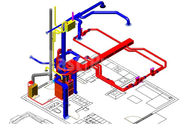
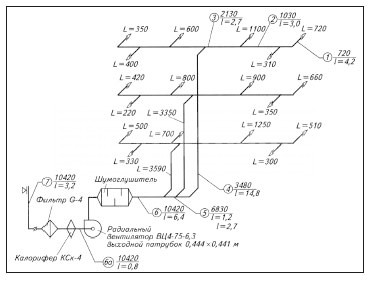
- Development of an axonometric diagram of air distribution throughout the system. Based on the diagram, a specific calculation methodology is determined, taking into account the features and tasks of the ventilation system.
- An aerodynamic calculation of air ducts is performed both along the main routes and all branches.
- Based on the data received, it is selected geometric shape and cross-sectional area of the air ducts are determined technical specifications fans and heaters. Additionally, the possibility of installing fire extinguishing sensors, preventing the spread of smoke, and the possibility of automatic adjustment ventilation power taking into account the program compiled by the users.
Development of a ventilation system diagram
Depending on the linear parameters of the diagram, the scale is selected, the diagram indicates the spatial position of the air ducts, the connection points of additional technical devices, existing branches, air supply and intake points.

The diagram indicates the main highway, its location and parameters, connection points and specifications branches. Features of the location of air ducts are taken into account architectural characteristics premises and the building as a whole. When drawing up a supply circuit, the calculation procedure begins from the point farthest from the fan or from the room for which the maximum air exchange rate is required. During compilation exhaust ventilation The main criterion is the maximum air flow rate. During calculations, the general line is divided into separate sections, and each section must have the same cross-sections of air ducts, stable air consumption, identical materials pipe manufacturing and geometry.
The segments are numbered in sequence from the section with least expense and increasing to the greatest. Next, the actual length of each individual section is determined, the individual sections are summed up, and the total length of the ventilation system is determined.
When planning a ventilation scheme, they can be taken as common for the following premises:
- residential or public in any combination;
- industrial, if they belong to group A or B according to the fire safety category and are located on no more than three floors;
- one of the categories industrial buildings categories B1 – B4;
- category industrial buildings B1 m B2 are allowed to be connected to one ventilation system in any combination.
If the ventilation systems completely lack the possibility of natural ventilation, then the diagram must provide for the mandatory connection of emergency equipment. The power and installation location of additional fans are calculated according to general rules. For rooms that have openings that are constantly open or open when necessary, the diagram can be drawn up without the possibility of a backup emergency connection.
Systems for suctioning contaminated air directly from technological or work areas must have one backup fan; turning the device into operation can be automatic or manual. The requirements apply to work areas of hazard classes 1 and 2. It is allowed not to include a backup fan in the installation diagram only in the following cases:
- Synchronized stop of harmful production processes in case of malfunction of the ventilation system.
- IN production premises Separate emergency ventilation with its own air ducts is provided. Such ventilation parameters must remove at least 10% of the volume of air supplied by stationary systems.
The ventilation scheme must provide a separate possibility of showering on workplace with increased levels of air pollution. All sections and connection points are indicated on the diagram and included in the general calculation algorithm.
It is prohibited to place air intake devices closer than eight meters horizontally from landfills, car parking areas, roads with heavy traffic, exhaust pipes and chimneys. Air intake devices must be protected special devices on the windward side. Resistance indicators protective devices taken into account during aerodynamic calculations common system ventilation.
Calculation of air flow pressure loss Aerodynamic calculation of air ducts based on air losses is done with the aim of the right choice sections to ensure technical requirements system and selection of fan power. Losses are determined by the formula:

R yd - value specific losses pressure in all sections of the air duct;
P gr – gravitational air pressure in vertical channels;
Σ l – the sum of individual sections of the ventilation system.
Pressure losses are obtained in Pa, the length of sections is determined in meters. If the movement of air flows in ventilation systems occurs due to a natural pressure difference, then the calculated pressure reduction is Σ = (Rln + Z) for each individual section. To calculate the gravitational pressure you need to use the formula:
P gr – gravitational pressure, Pa;
h – height of the air column, m;
ρ n – air density outside the room, kg/m3;
ρ in – indoor air density, kg/m3.
Further calculations for systems natural ventilation are performed according to the formulas:
Determining the cross-section of air ducts
Determination of the speed of movement of air masses in gas ducts
Calculation of losses by local resistance ventilation systems
Determination of friction loss
Determination of air flow speed in channels
The calculation begins with the longest and most remote section of the ventilation system. As a result of aerodynamic calculations of air ducts, the required ventilation mode in the room must be ensured.

The cross-sectional area is determined by the formula:
F P = L P /V T .
F P – cross-sectional area of the air channel;
L P – actual air flow in the calculated section of the ventilation system;
V T – speed of air flow to ensure the required frequency of air exchange in the required volume.
Taking into account the results obtained, the pressure loss during the forced movement of air masses through the air ducts is determined.


For each air duct material, correction factors are applied, depending on the surface roughness indicators and the speed of movement of air flows. To facilitate aerodynamic calculations of air ducts, you can use tables.
Table No. 1. Calculation of metal air ducts of round profile.


Table No. 2. Values correction factors taking into account the material of the air ducts and the air flow speed.
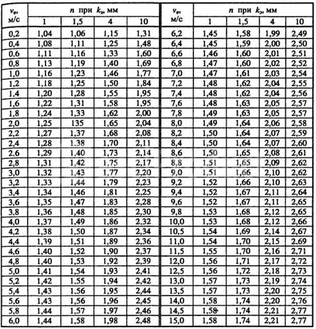
The roughness coefficients used for calculations for each material depend not only on its physical characteristics, but also on the speed of air flow. The faster the air moves, the more resistance it experiences. This feature must be taken into account when selecting a specific coefficient.
Aerodynamic calculation for air flow in square and round air ducts shows various indicators speed of flow movement with the same cross-sectional area of the nominal bore. This is explained by differences in the nature of vortices, their meaning and ability to resist movement.
The main condition for calculations is that the speed of air movement constantly increases as the area approaches the fan. Taking this into account, requirements are imposed on the diameters of the channels. In this case, the parameters of air exchange in the premises must be taken into account. The locations of the inflow and outlet flows are selected in such a way that people staying in the room do not feel drafts. If it is not possible to achieve the regulated result using a straight section, then diaphragms with through holes are inserted into the air ducts. By changing the diameter of the holes, optimal regulation of air flow is achieved. The diaphragm resistance is calculated using the formula:

The general calculation of ventilation systems should take into account:
- Dynamic air pressure during movement. The data is consistent with terms of reference and serve as the main criterion when choosing a specific fan, its location and operating principle. If it is impossible to ensure the planned operating modes of the ventilation system with one unit, installation of several is provided. The specific location of their installation depends on the features schematic diagram air ducts and permissible parameters.
- The volume (flow rate) of transported air masses in the context of each branch and room per unit of time. Initial data - requirements of sanitary authorities for cleanliness of the premises and features technological process industrial enterprises.
- Unavoidable pressure losses resulting from vortex phenomena during the movement of air flows at various speeds. In addition to this parameter, the actual cross-section of the air duct and its geometric shape are taken into account.
- Optimal air movement speed in the main channel and separately for each branch. The indicator influences the choice of fan power and their installation locations.
To facilitate calculations, it is allowed to use a simplified scheme; it is used for all premises with non-critical requirements. To guarantee the required parameters, the selection of fans in terms of power and quantity is done with a margin of up to 15%. Simplified aerodynamic calculations of ventilation systems are performed using the following algorithm:
- Determination of the cross-sectional area of the channel depending on the optimal speed of air flow.
- Selecting a standard channel cross-section close to the design one. Specific indicators should always be selected upward. Air channels may be enlarged technical indicators, it is prohibited to reduce their capabilities. If it is impossible to select standard channels in technical conditions It is envisaged that they will be manufactured according to individual sketches.
- Checking air speed indicators taking into account the actual values of the conventional cross-section of the main channel and all branches.
The task of aerodynamic calculation of air ducts is to ensure the planned ventilation rates of premises with minimal losses of financial resources. At the same time, it is necessary to achieve a reduction in labor intensity and metal consumption of construction and installation work, ensuring reliable operation installed equipment in various modes.
Special equipment must be installed in accessible places, with unhindered access to it for routine technical inspections and other work to maintain the system in working order.
According to the provisions of GOST R EN 13779-2007 for calculating ventilation efficiency ε v you need to apply the formula:

with ENA– indicators of the concentration of harmful compounds and suspended substances in the removed air;
With IDA– concentration of harmful chemical compounds and suspended substances in the room or work area;
c sup– indicators of contaminants entering with the supply air.
The efficiency of ventilation systems depends not only on the power of the connected exhaust or blower devices, but also on the location of the sources of air pollution. During aerodynamic calculations, the minimum performance indicators of the system must be taken into account.
Specific power (P Sfp > W∙s / m 3) of fans is calculated using the formula:
de P – power of the electric motor installed on the fan, W;
q v – air flow rate supplied by the fans during optimal operation, m 3 /s;
∆ p – indicator of the pressure drop at the air inlet and outlet of the fan;
η tot is the total efficiency for the electric motor, air fan and air ducts.
During calculations, the following types of air flows are taken into account according to the numbering in the diagram:
Diagram 1. Types of air flows in the ventilation system.
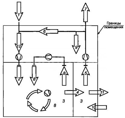
- External, enters the air conditioning system from the external environment.
- Supply. Air flows entering the duct system after preliminary preparation(heating or cleaning).
- The air in the room.
- Flowing air currents. Air moving from one room to another.
- Exhaust. Air exhausted from the room to the outside or into the system.
- Recirculating. The portion of the flow returned to the system to maintain the internal temperature within the specified values.
- Removable. Air that is removed from the premises irrevocably.
- Secondary air. Returned back to the room after cleaning, heating, cooling, etc.
- Air loss. Possible leaks due to leaky air duct connections.
- Infiltration. The process of air entering indoors naturally.
- Exfiltration. Natural air leakage from the room.
- Air mixture. Simultaneous suppression of multiple threads.
Each type of air has its own state standards. All calculations of ventilation systems must take them into account.
Let's start, perhaps, with natural and. As the name implies, the first type includes ventilation and everything that has nothing to do with devices. Accordingly, mechanical ventilation includes fans, hoods, supply valves and other equipment for creating forced air flow.
Good for the moderate speed of this flow, which creates comfortable conditions indoors for a person – the wind is not felt. Although correctly installed high-quality forced ventilation also does not bring drafts. But there is also a minus: at low air flow rates with natural ventilation, a wider cross-section is required for its supply. As a rule, the most effective ventilation is provided with complete open windows or doors, which speeds up the air exchange process, but can negatively affect the health of residents, especially in winter period of the year. If we ventilate the house by partially opening the windows or completely opening the vents, such ventilation requires about 30–75 minutes, and here the window frame may freeze, which may well lead to condensation, and cold air, taken over a long period of time, leads to health problems. Widely open windows speed up air exchange in the room; through ventilation will take approximately 4–10 minutes, which is safe for window frames, but with such ventilation, almost all the heat in the house goes outside, and for a long time the temperature inside the premises is quite low, which again increases the risk of disease.
We should also not forget about the increasingly popular supply valves, which are installed not only on windows, but also on walls inside rooms (wall supply valve), if the window design does not provide for such valves. The wall valve provides air infiltration and is an oblong pipe installed through the wall, closed on both sides with grilles and adjustable from the inside. It can be either completely open or completely closed. For convenience in the interior, it is recommended to place such a valve next to the window, since it can be hidden under tulle, and the flow of passing air will be heated by radiators located under the window sills.
For normal air circulation throughout the apartment, it is necessary to ensure its free movement. To do this on interior doors install transfer grilles so that the air moves smoothly from supply systems to the exhaust, passing throughout the house, through all the rooms. It is important to consider that the correct flow is considered to be the one in which the smelliest room (toilet, bathroom, kitchen) is the last. If it is not possible to install a flow grille, it is enough to simply leave a gap between the door and the floor, about 2 cm. This is enough for air to move easily around the house.
In cases where natural ventilation is not enough or there is no desire to provide it, they switch to using mechanical ventilation.
Do you dream of having a healthy microclimate in your home and not a single room smelling musty and damp? In order for the house to be truly comfortable, it is necessary to carry out proper ventilation calculations even at the design stage.
If you miss this during the construction of a house important point, in the future we will have to decide whole line problems ranging from bathroom mold removal to new renovations and ductwork installations. Agree, it’s not very pleasant to see breeding grounds for black mold in the kitchen on the window sill or in the corners of the children’s room, and to plunge into renovation work all over again.
The article we present contains collected useful materials for the calculation of ventilation systems, reference tables. The formulas are given, visual illustrations And real example for premises of various purposes and a certain area, demonstrated in the video.
At correct calculations and proper installation, ventilation of the house is carried out in a suitable mode. This means that the air in living areas will be fresh, with normal humidity and without unpleasant odors.
If the opposite picture is observed, for example, constant stuffiness in the bathroom or other negative phenomena, then you need to check the condition of the ventilation system.
Image gallery
Conclusions and useful video on the topic
Video #1. Useful information according to the operating principles of the ventilation system:
Video #2. Along with the exhaust air, heat also leaves the home. Calculations of heat losses associated with the operation of the ventilation system are clearly demonstrated here:
Correct calculation of ventilation is the basis for its successful functioning and the key to a favorable microclimate in a house or apartment. Knowledge of the basic parameters on which such calculations are based will allow not only to correctly design the ventilation system during construction, but also to adjust its condition if circumstances change.
Ventilation plays a vital role in creating an optimal microclimate in the home. A properly designed ventilation system ensures that contaminated air, harmful gases, vapors and dust that affect the health of people in the living space are removed from the premises. When designing ventilation systems, a huge number of calculations are made, which take into account many factors and variables.
Air ducts play an important role in the performance of a ventilation system, namely their length, cross-section and shape. It is extremely important that the calculation of the cross-section of the air ducts is carried out correctly, since this will determine whether the air duct system can pass sufficient quantity air, air flow speed and trouble-free operation ventilation system as a whole. Thanks to proper calculation of the area of the air channels, vibration and aerodynamic noise produced air currents, will be within acceptable limits.
- Contact the professionals. The calculation will be done efficiently, but expensively.
- Make an independent calculation using formulas for calculating specific air losses, gravitational support, cross-section of air ducts, the formula for the speed of movement of air masses in gas ducts, determining friction and resistance losses.
- Use an online calculator.
Calculation of duct cross-section


