Tool sharpening
TO category:
Tool sharpening
Tool sharpening
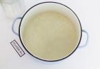
Sharpening the chisel. The tool is placed on the tool rest of the sharpening machine and, pressing lightly on it, is slowly and smoothly moved across the entire width of the sharpening wheel. During operation, the chisel should be turned over and sharpened first one side or the other, periodically cooling the cutting part in water.
The cutting edge of the chisel after sharpening should have the same width and inclination to the axis on both sides of the tool. Only in this case will the chisel be sharpened correctly.
For cutting cast iron and bronze, the sharpening or sharpening angle of the chisels is 70°, for medium-hard steel - 60°, copper and brass - 45°, aluminum and zinc - 35°. The sharpening angle is checked using a template, which is a plate with angular cuts of 70°, 60°, 45°, 35° (Fig. 2).

Rice. 1. Sharpening the chisel

Rice. 2. Template (a) and checking the sharpening angle of the chisel (b)

Rice. 3. Sharpening the scriber
After sharpening cutting edge The chisels are set on an abrasive stone, that is, they remove irregularities from it.
Sharpening the scriber. First, check the installation of the tool rest. If it is positioned correctly, that is, the gap between it and the abrasive wheel does not exceed 2-3 mm, you can start working.
Turn on the electric sharpener, take the scriber with both hands and, leaning on the tool rest with your left hand, press the working part of the tool against the side surface of the grinding wheel under small angle to it (Fig. 2). In order for the scriber to be sharpened evenly and correctly, it must be constantly rotated around its axis.
Sharpening the center punch. Having adjusted the gap between the tool rest and the grinding wheel, take the center punch with both hands and, positioning left hand on a tool rest, set the center punch at an angle of 30-40° to work surface circle (Fig. 3).
Having turned on the electric sharpener, press the working part of the punch against it and sharpen the tool, turning it around its axis.
With the help of sharpening, the working part of the cutting tool is restored, i.e., the optimal shape, size and roughness of its cutting edges are obtained. Repeated operations of sharpening a dull tool are called resharpening.
Sharpening cutters. Wear on the rear surface is determined by the size, wear on the front surface is determined by the width B and depth Hl of the hole. Depending on the processing conditions, wear hard alloy can occur only on the front or only on the back surface or on both surfaces at the same time.

Rice. 4. Sharpening the cutter on a grinding machine
If the wear of the cutters does not exceed the permissible value, then the sharpening allowance is 0.6-0.9 mm.
Sharpening of cutters is carried out on sharpening and grinding machines (sharpeners), universal sharpening machines and special sharpening machines. The installation of the cutter on the sharpener rests when sharpening the front surface is shown in Fig. 4, a; when sharpening the main rear surface - in Fig. 4, b.
When making calculations, they take into account whether the angle I is positive or negative and substitute it into the formulas with a plus or minus sign, respectively.
Sequence of operations for sharpening and finishing a carbide cutter:
1) sharpening the front surface;
2) sharpening of the rear main surface along the holder;
3) sharpening of the rear auxiliary surface along the holder;
4) sharpening the chamfer along the front surface;
5) sharpening of the rear main surface along the plate;
6) sharpening of the rear auxiliary surface along the plate;
7) sharpening of the rear surface along the radius of the apex;
8) finishing the chamfer on the front surface;
9) finishing the ribbon on the back surface.

Rice. 5. Scheme for calculating the installation angles of the cutter when sharpening in a three-rotary vice on a universal sharpening machine
Tool sharpening
Any cutting tool It gets dull during use and therefore needs to be sharpened from time to time. This operation is best and easiest to carry out on a sharpening machine or other mechanical sharpener.
Sharpening a chisel on a sharpening machine
Sharpening chisels and crosspieces. Taking the chisel in your hands, carefully apply it to the rotating circle and move it left and right with light pressure. Both faces are sharpened alternately. The angle between them - the sharpening angle - can be different and varies depending on the hardness of the material being processed within the following limits: for aluminum and zinc - 35°, copper and brass - 45°, steel - 60°, cast iron and bronze - 75°. It is most convenient to check sharpening angles using a template.

The rules for sharpening a crosspiece are the same as for a chisel.
Sharpening drills. The picture below shows the front of a twist drill.
Front of twist drill
Helical grooves along the axis of the drill are used to remove chips. The edge between the groove plane and the flank surface is the cutting edge. The angle between the edges is usually 116-118°, but it can vary, depending on the hardness of the material being processed, from 90 to 140°. When sharpening, hold the drill with your left hand, perhaps closer to the front, and hold the shank with your right hand, rocking the drill smoothly.
Drill sharpening
In this case, the following conditions must be observed: a) the cutting edges must be symmetrical, have the same angle of inclination and the same length; b) the transverse edge must make an angle of 55° with the cutting edge. Correct sharpening is checked using a template.

Sharpening a center punch is similar to sharpening drills. The tool is held with the left hand, pressing it against the abrasive wheel, and with the right hand it is evenly rotated to obtain an even cone. The sharpening angle is 60°, for marking centers - 120°.
Remember that you cannot press hard on the tool while sharpening, otherwise its working end will heat up too much and may come loose and lose its hardening. During operation, hot particles are released from the tool and the abrasive wheel, which can get into your eyes. When sharpening, use safety glasses or protective screen!
If particles get into your eyes, consult a doctor immediately.
SHARPENING CUTTING TOOLS
Any cutting tool becomes dull sooner or later during use. If it is “disposable”, it has one way - to the landfill. If the instrument can really be restored, why not take advantage of this opportunity? Based on this, we decided to prepare an article about how a cutting tool is brought to life.
Let's clarify the terminology. The cutting edge of a tool is formed by two converging planes (or curves, like drills). The sharpening angle is the angle at the apex of convergence of these planes. The sharpness of an edge can be represented as the reciprocal of the width of the “platform” at the top or the diameter of the circle inscribed in it. In practice, the smoother the converging surfaces, the sharper the RO will be. Sharpening angles different instruments vary and depending on the quality of the steel and the material being cut are: for a chisel – 17–25 degrees, for a plane iron – 25–40, for a chisel – 30–40, for a metal chisel – up to 60, for scissors – 45–60, for knives – 20–30 degrees.
All cutting tools, from the point of view of sharpening techniques, can be divided into “knives” (that is, what longer than width grindstone) and “cutters” (what is narrower than stone: saws, cutters, cutters and drills). The techniques for sharpening the latter are different from everything else.
In addition to the knives themselves, the category of “knives” includes scissors, electric jointer and planer knives, as well as other long items. Important Note: Scissors and woodworking equipment knives are sharpened on one side only. Before sharpening, the tool must be cleaned of dirt, sawdust, resin, etc., since these substances easily and irreversibly clog the sharpening stone.
Knife sharpening
First you need to consider the cutting edge and decide which abrasive to start with. If the knife is new or very dull, it may be worth starting with a rough stone. Good sharpening of a cutting tool is just the ability to maintain the same angle when moving along the stone. Important note: never sharpen knives on a high-speed sharpening wheel - it instantly releases and burns the cutting edge.
So, let’s wet the whetstone with water, place it on old newspapers or, better yet, in a recess hollowed out in the board according to the shape of the stone, and move the knife along the stone, observing the sharpening angle. The knife should approach the stone at an angle as close to straight as possible. But since the stone is narrow, you will have to make some kind of oblique movement, moving the knife diagonally, that is, simultaneously along the stone and along the knife.
A big mistake would be to sharpen the cutting edge in sections. An absolutely precise transition will not work - a step will form and the knife will not cut well. It is necessary to sharpen until a burr appears on the edge, which is turned up, which is revealed by a slight movement of your finger across the knife from the butt to the edge (you should not do this along the edge - you can cut yourself). When the burr appears along its entire length, the knife needs to be turned over and sharpened on the other side.
 Don't try to sharpen only those areas where there is no burr. A continuous burr indicates that one chamfer of the cutting edge of the knife has become flat along its entire length. When, when sharpening the second side, a burr appears on the already sharpened side, you need to turn the knife over again and switch to a finer abrasive.
The smaller the abrasive grain, the smoother the chamfers and the sharper the edge. After the fine stone, you need to move on to sandpaper, laid with the abrasive side up on a smooth surface, for example, on a piece of glass or steel or on a flat part of the workbench.

Typically, a cheap double-sided sharpening stone is used first and then, in succession, sandpaper with a grit of 120, 400, 600 (or 800) and sometimes 1200. The most difficult and simple thing in this process is to maintain the same angle during all movements of the knife. It is worth noting that constant practice is better than any ingenious devices - they break and, moreover, cost much more than the stone, which, by the way, is also present in them. The trick is to move the tool you are sharpening with your wrist still and look carefully at the top plane of the tool. Then the angle is maintained very accurately.
The scissors sharpen only from the chamfer; the plane adjacent to the other jaw is only leveled using fine sandpaper.
Jointer knives are also sharpened only from a chamfer. Their peculiarity is that you need to frequently touch the edge to a ruler or glass in order to see the straightness of the cutting edge and avoid rounding it.
Sharpening chisels and plane irons
Chisels and plane irons have a lot in common. If the cutting edge is severely dull or has gouges caused by knots or nails, it must first be profiled. By the way, the same is done when making a wood cutter from a hardened blank.

The most effective way to sharpen plane iron is with an electric sharpener.
Here we need a high-speed electric sharpener. Often dipping the iron into water to cool, you need to make a chamfer with an angle slightly sharper than 25 degrees. In no case should you thin the edge of the piece of iron until a cutting edge appears, since the enormous friction of the abrasive on the metal heats the latter, and if you try to sharpen on a high-speed stone, the cutting edge will immediately release and the tool will be damaged.
When the thickness of the edge becomes about half a millimeter, you need to use a square to check the perpendicularity of the cutting edge to the axis or side of the plane iron.
There are two ways to finally sharpen a piece of iron. It’s best to use a low-speed electric sharpener with a wet stone (pouring water into a tray and evenly pressing the iron against the stone). If the width of the latter is not sufficient, then it is necessary to move the piece of iron from side to side.

A bolt with two nuts will help you maintain the required angle when sharpening a piece of iron for a plane.
If you don’t have such a sharpener, you will have to work manually on an abrasive stone moistened with water. It is better to put it in a recess in the board - it is more convenient to hold. The iron is placed on the stone at a chosen angle or, more simply, with a chamfer on the stone, rocking back and forth until it sits with the entire chamfer. They sharpen with movements along the stone and back, or better yet, using the future cutting edge to describe it in a figure of eight, in order to achieve uniform wear of the stone and maintain its flatness. When a burr appears, place the iron flat on the stone and remove it with a couple of movements, after which they move on to a finer abrasive, for example, by turning over a double-sided stone.
Final sharpening is done by placing sandpaper of varying degrees of grain on the glass.
A little trick. A bolt with a nut and two large washers can be used as a simple holding device correct angle tilt of the plane iron (see figure).
Sharpening wood saws
Wood saws, as a rule, are not always sold sharp enough (and large-toothed ones, for the most part, are simply dull). Again the need for sharpening arises, and it is different for each type of work.
If the saw is not set apart enough, it must be set apart first. If you don’t have specialized wiring at hand, you can get by with pliers. The saw is clamped in a vice with the teeth up, sit down so as to look along the blade, and bend the teeth in different sides through one, with each movement tilting the pliers at the same angle. Usually there is always a small wiring initially, and you just need to increase it if you are dealing with raw wood or big saws. If the saw is small and for precision work, it is quite possible to leave the factory wiring.

A triangular file is used to sharpen the teeth. They are used to sharpen the inner (relative to the setting) side of the saw teeth. The file is held so that the cutting edge angle is 60–45 degrees. In fact, it is easier and faster to sharpen one side of the teeth first, and then, turning the saw over, sharpen the teeth of the other side. In this case, the movements are more of the same type - the saw becomes sharper.
When sharpening saws, it is better to work alone and in silence, turning off interference in the form of radio and TV, since careless movement either damages the tool or causes a wound that is difficult to heal. Advice: if the saw tends to move to the side when cutting, this means that the teeth are unevenly spaced - you need to increase their deviation on the side in which the saw is moving.
Sharpening saw blades
Circular saws sharpened from the back surface, when working facing the material being processed. The front one, which runs into the material when sawing, remains as is.
The disc can be sharpened or directly in the machine (if we're talking about about the equipment for the machine), or by removing it from the machine or circular saw. In the first case, you first need to unplug the plug from the socket to avoid accidentally starting the machine. The disk should be wedged by placing a thin piece of wood on both sides of it and pressing it against the teeth. The tooth from which sharpening begins must be marked with a felt-tip pen on the side so as not to make mistakes in the work. When sharpening the first tooth, remember the number of movements with a file or diamond needle file - all other teeth will have to be sharpened with the same force and the same number of movements of the abrasive tool as the first.
If the blade has been removed from the machine, clamp it in a vice and follow the same procedures as described above.
Next, you need to return the disk to the machine and saw the unnecessary wood. If there is a lot of noise or uneven feed, check whether the height of the teeth is the same. To do this, bring a felt-tip pen to the cutting edge and slowly turn the disk by hand one turn in the direction opposite to the direction of rotation. There will be a mark on each tooth. By examining the disc, you may find teeth that are higher or lower than others. If the difference is large, it is necessary to carefully reduce the height of the teeth that are too long.
Sharpening cutters
The cutters are sharpened along the back or front surface.

Before sharpening, it is necessary to first separate the guide bearing from the cutter, otherwise the tool may be damaged.
Shaped end mills It is easier to sharpen along the front surface - either with a thin diamond stone, or (if the chip flute is narrow) with sandpaper wrapped around a hardwood strip or strip of steel. As the front surface grinds down, the edge will become sharper and the diameter of the cutter will decrease (slightly).
With cutters with a guide bearing, you must first remove the bearing and only then sharpen them. An attempt to save a minute will end in a ruined bearing and a damaged cutter.
Sharpening turning tools
Turning cutters are sharpened on the front and back surfaces. There is only one nuance - the cutter tapers downwards, therefore, so that its side planes in no case come into contact with the workpiece, contact should only be along the cutting edge.
Quick-cutting and carbide-tipped cutters are sharpened on a grinding wheel. If the machine does not have a water supply, frequently dip the cutter in a container of water.
Drill sharpening
When sharpening a drill, you need to hold it so as to obtain the desired angle of convergence of the cutting edges. In this case, the cutting edge must be symmetrical.

The easiest way is to draw a line on the tool tool with a felt-tip pen and hold the drill parallel to it. However, simply placing the drill along the line is not enough; you should also turn it desired angle around the axis, and then 180 degrees relative to the first position.
An angle is needed between the edge of the drill and the plane of the table, that is, the outer edge must be below the center, otherwise the drill will not cut the material, but will ride along it with its back surface. To control this angle there is various devices, but it’s easier to stand or sit at a table so that the glare from the lighting is on the outer part of the cutting edge, and then, without changing your body position, turn the drill in your fingers and catch the glare again - the edges will be sharpened at the same angle.
Sharpening a drill along the back surface is called single sharpening; it leaves a rather large bridge in the center, which does not cut, but scrapes the metal. If you sharpen it, the drilling speed will increase. There are many ways to sharpen a jumper. In factories it is sharpened with thin abrasive or diamond wheels or on the corner of a wide stone. But you can sharpen the jumper as shown in the photo. Safety glasses are strictly required when sharpening.
Electric sharpener
To make work easier when sharpening tools, there are various electric sharpeners and sharpening machines.
Choosing an electric sharpener is extremely simple. Such a machine consists of an asynchronous motor (such motors are perfectly mastered by industry), grinding wheels(they are replaceable and can be changed using wrench) and casings. If the sharpener is not taken for industrial use, then the brand does not have such of great importance. Such equipment is turned on for a short time, and its resource will be consumed extremely slowly - even an inexpensive machine will last for many years.
The diameter of the wheel directly affects the price of the sharpener, so an amateur craftsman or small enterprise should not chase larger diameters.
When inspecting the electric sharpener before purchasing, try moving the shaft. If it not only rotates, but also walks, then you have a marriage. Spin the stone with your hand and look at the free end of the shaft, does it vibrate? It is best, of course, to turn on the sharpener, but not all stores allow you to do this.
Sharpening machines
Sharpening machines are divided into three groups.
The first is actually a high-speed electric sharpener (about 3000 rpm), equipped with replaceable holders for different types tool.
The second is highly specialized machines, for example for drill sharpening. Often no other cutting tool can be sharpened on them.
The third is machines equipped with low-speed water-cooled (“wet”) wheels. Rotation speed – 80–150 rpm. They can sharpen and straighten any cutting tool, from high-speed steel drills to carbon steel knives. Low speed and water cooling – the necessary conditions for producing the thinnest and sharpest cutting edge. Often such machines also have a polishing wheel for polishing the cutting edge.
Working with an electric sharpener and sharpening machine
After working on the machine with a “wet” wheel, do not forget to pour the water out of the pan and do not leave the stone in the water on one side for a long time - the stone becomes saturated with water, loses strength and turns into an eccentric, breaking the machine.

Abrasive wheels should always “run” onto the cutting edge of the tool being sharpened, and polishing wheels (leather, felt, vulcanite) should “run away”, that is, rotate “away from the worker”. Do not try to polish by rotating the wheel towards yourself - the object being processed will crash into the wheel, be grabbed by it and thrown towards the operator. In addition to damage to the circle, you can get serious injury.
If you are installing a polishing wheel on a high-speed electric sharpener, rotate the guard 180 degrees. To work on the polishing pad, either turn the machine around or approach it from the other side.
Scribblers (needles) are used for drawing lines (scores) on the marked surface using a ruler, square or template. Scribblers are made from tool steel U10 or U12. To mark on a steel, well-treated surface, brass scribers are used, and on aluminum, marks are applied with a sharply sharpened pencil.
Three types of scribers are widely used: round, with a bent end and with an insert needle.
A round scriber is a steel rod 150 - 200 mm long and 4 - 5 mm in diameter, one end of which is hardened to a length of 20 - 30 mm and sharpened at an angle of 15°, and the other is bent into a ring with a diameter of 25 - 30 mm (Fig. 32, A).
A scriber with a bent end is a steel rod, sharpened on both sides, one end of which is bent at an angle of 90° (Fig. 32, b). The middle part of the scriber is thickened and knurled for convenience. Use the bent end to make marks in hard to reach places(Figure 32, c).
The scriber with an insert needle (Fig. 32,d) is made like a clock screwdriver; sharpened and hardened steel rods can be used as an insertion needle.
Pocket marker scriber
V. A. Andreeva (Fig. 32, l) is made in the form of a pencil with a retractable tip. The body of the scriber consists of two parts, rotating relative to each other on four balls, which are wound through longitudinal grooves during assembly. A holder is provided to secure the scriber in the worker’s pocket and to prevent it from rolling off the stove. A rod made of VK6 hard alloy, sharpened to a cone with an angle of 20°, is soldered onto the working rod. The scribers must be sharp. Conical surface The scriber should be well processed (smooth), not scratch the ruler or square. The sharper the working part of the scriber, the thinner the marking mark will be and, therefore, the higher the marking accuracy. The scribers are sharpened on sharpening machines (Fig. 33). The scriber is taken by the middle with the left hand, and with the right hand by the end opposite to the one being sharpened. Maintaining a constant angle of inclination relative to the abrasive wheel, with light pressure apply the scriber with a cone to the rotating circle, rotating it evenly with your fingers right hand. To avoid tempering, the scriber tip is periodically cooled in liquid.


Punch-fitter a tool used for making indentations (cores) on pre-marked lines. Cores are made so that the marks are clearly visible and are not erased during the processing of the part. Cores are made from tool carbon steel U7A, U8A, 7ХФ, 8ХФ. The working part of the punches (cone) is thermally treated over a length of 15 - 30 mm to a hardness of HRC 55 - 59, and the impact part - over a length of 15 - 25 mm to a hardness of HRC 40 - 45. The middle part of the punch is knurled (knurled) for ease of use .
Punch punches are ordinary, special, spring (mechanical) and electric.
An ordinary punch (Fig. 34, a) is a steel rod with a length of 100, 125 and 160 mm and a diameter of 8, 10, 12 mm, its striker has a spherical surface. The point of the punch is sharpened on a grinding wheel at an angle of 60° (Fig. 3A, 6). For more precise markings, small punches with a tip sharpened at an angle of 30-45° are used.


Rice. 38. Punchers: a - pneumatic “gun”, b - pneumatic portable A. N. Podvysotsky
For center punches, to mark the centers of holes to be drilled, the tip is sharpened at an angle of 75°.
High-performance punches are special, for step marking, spring, and electric.
Special punches(Fig. 35,a) are used for punching small holes and rounding small radii. The use of such a center punch significantly improves marking quality and productivity.
Center punch for step marking(Fig. 35.6) consists of two punches - the main 7" and the auxiliary 2, fastened with a common bar 3. The distance between them is adjusted using holes in the bar 3 depending on the pitch of the holes being marked. The first recess is punched with a center punch 7. Then into the resulting punch 2 is inserted into the recess and the recess is punched with a hammer on punch 7. After this, punch 2 is moved to the next position. The pitch between the holes is maintained automatically, which ensures accurate marking and increased productivity.
A punch with a magnifying glass by S. M. Nenastev (Fig. 35, c) consists of two clamps connected by a screw 6 and tightened after installing a magnifying glass 8 according to the worker’s vision. A 3-5x magnifying glass is installed in one clamp 7, the other clamp 5 is used to install the magnifying glass on the center punch 4 at the height of its mounting.
Spring center punch(Fig. 36) is used for precise marking of thin and critical products. The principle of its operation is based on the compression and instant release of a spring.
The punch has a body screwed together from three parts 3, 5, 6. The body contains two springs 7, 7 7, a rod 2 with a punch 7, a striker B with a shifting block 10 and a flat spring 4. When pressing on the product with the tip of the punch, the inner end of the rod 2 rests on the cracker, as a result of which the striker moves upward and compresses the spring 7. Having rested against the edge of the shoulder 9, the cracker moves to the side and its edge comes off the rod 2. At this moment, the striker, under the influence of the force of the compressed spring 7, strikes the end of the rod with the center punch hit. Immediately after this, spring 7 7 restores the initial position of the center punch. The impact force of 10-15 kgf is regulated by screwing or unscrewing the thrust cap 6. Instead of the punch 7, a stamp can be inserted into the rod 2 and then the mechanical punch can be used for branding parts.
Electric punch(Fig. 37) consists of a body 6, springs 2 and 5, striker 3, coil 4, punch 7. When pressed with the tip of the punch mounted on the mark electrical circuit closes and the current passing through the coil creates a magnetic field, the striker is instantly drawn into the coil and strikes the punch rod. During the transfer of the punch to another point, spring 5 opens the circuit, and spring 2 returns the hammer to its original position. The electric punch has high performance.
Air gun"(Fig. 38, a) is used for various core work. For convenience, it is equipped with a handle 7, located at an angle to the axis of the body, and a start button 2.
Pneumatic Portable Punch A. N. Podvysotsky (Fig. 38.6) differs from other punches in its small size and the absence of a handle, which is used by the punch itself.
Compasses used for marking circles and arcs, for dividing segments, circles and for geometric constructions. Compasses are also used to transfer dimensions from measuring rulers for detail.


Marking compasses are: simple or with an arc, precise (Fig. 39,a) and spring (Fig. 39,6). A simple compass consists of two hinged legs (Fig. 39, a), whole or with insert needles (Fig. 39, a), it allows installation the required solution fix the legs with a screw.
Innovative mechanics, trying to improve the accuracy of markings, are improving the designs of compasses.
L. S. Novikov developed the design of a compass (Fig. 39, d), consisting of two legs 6, equipped at the ends with hardened needles 4, and two detachable lenses 7 with fivefold magnification. The lenses are installed so that the ends of the needles 4 are in focus. This makes it possible to clearly see the tip of the needle and accurately align it with the divisions of the scale bar or with the marks of the part being marked.
To accurately set dimensions, the compass has a micrometric screw 2. The advantages of this compass: convenience and high accuracy installations. However, its parts require especially careful handling and storage.
A special feature of the design of the compass (Fig. 39, a) is device 3 for installing the compass directly on its scale with an accuracy of 0.2 mm. The 7 and 2 micrometer screws increase the accuracy of this installation. Replaceable needles 4 are tightened with nuts 5.
The marking caliper (Fig. 40,a) is designed for precise marking of straight lines (Fig. 40,6) and centers (Fig. 40,a).
Marking caliper(Fig. 41) is used for marking circles of large diameters. It has a rod 3 with millimeter divisions and two legs - fixed 2 with a locking screw 7 and movable 8 with a frame 5 and a vernier 6, a locking screw 4 for securing the frame 5. The locking screw 7 is used to secure the insertion needle 9, which moves down and up and can be installed at different levels.

In Fig. Figure 42 shows an improved marking caliper for marking planes. It has a rod 9 with a thickened end into which a cutter 2 is installed. A frame 6 with a vernier 3 moves along the rod. At the bottom of the frame there is an insert 13, into the hole of which a replaceable centering conical support is inserted, secured with a clamp 12.
Frame 6 is connected to clamp 8 using a micrometric screw 7 7. Frame 6 is moved along the rod manually and secured with clamp 4. Micrometric feed of the frame is carried out by turning nut 10 with the clamp secured by screw 7.
When marking, first install a centering support corresponding to the base hole, then install a cutter on the plane of the part to be marked. After this, check the horizontal position of the caliper at level 5, secure the cutter with a locking clamp 7 and make the marking.
Reismas is the main tool for spatial marking. It is used for applying parallel, vertical and horizontal lines, as well as to check the installation of parts on the plate. Reismas consists of a cast iron base 2 (Fig. 43,a), vertical stand(tripod) 5, a screw with a nut 6 for fastening the scriber 4, a set screw 3 for setting the needle for precise adjustment of the size, a bar 7 and a coupling 7. The use of a surface gauge is shown in Fig. 43.6.
For more accurate markings, a surface gauge with a micrometric screw is used.
Gauge gauges for marking are described in Chapter XIX "Basics of measurement".
Install the electric sharpening tool so that the gap between it and the abrasive (sharpening) wheel does not exceed 2 - 3 mm. Having turned on the electric sharpener, take the scriber with both hands and, leaning on the tool rest with your left hand, rotate the scriber around its axis. Sharpen on the side surface of the abrasive wheel at a slight angle to it. The working part of the scriber is sharpened to a length of 15 - 20 mm.
 |
Having adjusted the gap between the tool rest and the sharpening wheel, take the center punch with both hands and place it at an angle of 30 - 40° to the periphery, and not to the side surface of the wheel, as when sharpening a scriber. Having turned on the electric sharpener, turn the center punch around its axis, leaning on the tool rest with your left hand.
Check sharpening angles with templates.
Sharpening angles for cast iron, bronze 60°, for soft metals 45°.
Sharpening the marking compass
Prepare the machine in the same way as when sharpening a scriber and center punch. The legs of the compass are sharpened on the side surface of the abrasive wheel. Together, the legs of the compass are sharpened on four sides to a length of 15 - 20 mm so that the points of both legs converge at one point.
The legs of the compass are tucked onto the block.
When working on an electric sharpener, you must use a protective shield or goggles.
Questions
- What parts does the electric sharpener consist of?
- List the rules safe work on an electric grinder.
- On what surface of the abrasive wheel are scribers sharpened?
- Tell us about the sequence of sharpening the center punch.
- How to sharpen a marking compass?
Exercises
- Check the condition of the scribers and punches and refill them.
- Check that the compass is correct and prepare it for use.
On the prepared surface of the workpiece, using a scriber and a ruler, draw an arbitrary line (mark) AB.

a - holding arcs; b - drawing a tangent to the VG to the arcs.
Stepping back from the ends of line AB by 10 - 15 mm, make two indentations O and O 1 on it with a center punch. Using a given compass opening (in our example, 30 mm), install the leg into recess O and draw one arc, and from recess O 1 another arc.
Concerning both arcs, a ruler is drawn along the ruler with a scriber mark VG, which will be parallel to the previously drawn mark - AB. The parallelism of the marks is checked with a ruler. The distance between the marks at any points should be the same (30 mm).
Questions
- Which lines are parallel to each other?
- How to draw a score parallel to the straight edge of a workpiece using a ruler and compass if the distance between the edge and the score is 40 mm?
- How do you check if the marks are parallel?
Exercises
- Draw parallel marks using a ruler and compass at a distance of 20 mm, 40 mm, 65 mm.
- In a rectangle with sides 60 and 130 mm, draw horizontal and vertical center lines using a ruler and compass. Determine which lines are parallel.
“Plumbing”, I.G. Spiridonov,
G.P. Bufetov, V.G. Kopelevich

When two straight lines intersect, an angle is formed; Therefore, let’s consider marking by pairing the sides different angles. The figure below shows the conjugations of right, acute and obtuse angles. Conjugation of sides of angles a - straight; b - acute; c - stupid. The construction comes down to finding the center of the arc, which would touch both sides of the angle. Let the radius R of the arc (conjugation) of the circle be 40...

A perpendicular (figure below) is a straight line that makes a right angle with another straight line or plane. Perpendiculars to a straight line (a) and a plane (b) When cutting a thread in a hole with a tap, the tap is placed perpendicular to the surface of the part (figure below). Perpendicularity of the tap to the hole being cut Before drilling deep holes in parts, it is necessary to check the perpendicularity of the drill installed in…

You have already worked with the student protractor. Using it, you can build any angle. Let us recall the construction of a 45° angle, which is often found when marking: Construction of a 45° angle using a protractor. On the prepared surface of the workpiece, draw a straight line AB. Mark a point on this mark and make a mark O with a center punch. Apply a protractor to the mark so that its starting point...
The marking is carried out slowly, carefully on the marking plate. Workplace The marker should be well lit. Before marking, they study (read) the drawing and determine the main dimensions of the part (length, width, height). The workpiece must have an allowance for processing. The workpiece is checked for machinability by trial filing, cutting or bending. The workpiece must be clean, free from burrs and sagging (if it is...
K category: Locksmith work
Sharpening the marking tool
In order for the marking to be made accurately, to be clearly visible and not to be erased, use a well-sharpened, serviceable marking tool. Therefore, from time to time you need to sharpen scribers, compasses and punches, which become dull most often. Sharpening is carried out on an abrasive grinding wheel; its presence in every home workshop is mandatory. The scriber can be sharpened by determining the sharpening angle by eye: it must be positioned at a slight angle to the surface of the grinding wheel and sharpened to a length of 12-15 mm. The point of the punch is sharpened at an angle of 60-70°, the angle is controlled by measuring it with a protractor or comparing it with a template. In order to sharpen the legs of the compass, they are brought together and sharpened on four sides into a square at a length of 15-20 mm, trying to ensure that both points converge at one point. Final finishing The legs of the compass need to be made by sharpening them one by one on a whetstone.