Do-it-yourself repair of LED lamps and chandeliers is not often required. Let's say, foolishly bought this one-eyed snake in FixPrice, and then torment with it. It is first discovered that the LED light itself is comparatively small compared to the flexible arm. When you stick this economy into a laptop, you get the impression that now you will turn out the USB port from which this miracle is powered. Finally, I manage to get comfortable, and it is discovered that the entire keyboard cannot be covered by the LED light in any way. And what is it for then? As a result, it turns out that it is more profitable not to take a steam bath, but just take LED bulbs for yourself and, without any twinge of conscience, spend 20 watts on lighting the entire room. And now about everything in more detail.
Where do LED lamps come from in the house, and how to repair them
LED lamps are good because they burn brightly at a relatively low voltage and low current. But not the Chinese "snakes" designed for the USB port. The bottom line is as follows:
- Two wires fit to the corresponding terminals of the LED lamp connector. One of them sits on the ground, and the second starts up on the +5 V bus.
- All this economy inside a flexible metal corrugation goes to the very end of the lamp, where a small LED is attached.
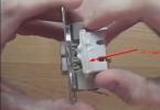
- The improvised light bulb is covered by a small lens, and after the breakage, everything looks exactly like in our photo (in fact, this is the broken LED lamp for the USB port, which was bought from FixPrice, and we are going to fix it).
Upon closer inspection, it turned out that the white LED inside is connected in series with a limiting resistance of 20 ohms. Both of them looked slightly burnt, or stained with some kind of tar. The resistor, as it should already be clear, rang out normally, and the LED refused to light up. When tested on USB power, as well as on battery, the effect remained zero. A closer acquaintance with the LED showed that its design is extremely simple:
- The metal bridge is torn in the middle to form a hole. Two legs are brought out from the edges under the base of the LED.
- The air is evacuated from the flask.
- A thin bar in color, reminiscent of copper, is thrown across the abyss.
- The LED cathode is actually larger than the anode, it is on it that the glow is produced in the center of the lens (in the form of a bullet).
As a result, we can conclude that the tightness of the LED was broken for some reason, which was the real reason for the failure of this device. We would say that this is a typical oxidation reaction. Simply put - burning. Now we can say with confidence that the intensity of the glow dropped until the USB lamp went out completely. When studying the technical documentation of analogs (BL-L102UWC), it turned out the following ...
LED forward voltage should not exceed 4.5V
But the real working one is 2.7 V. Now it is clear that the resistor plays not only a limiting role in current, but also forms a divider with the LED at the same time. As a result, the operating parameters are maintained. Of course, no one gives the resistance of the p-n junction of the LED directly, but it can be calculated indirectly from the current-voltage characteristic. In our case, for example, it will be R = 2.7 V / 30 mA = 2700/30 = 90 Ohm. When the USB bus is powered within 5 - 5.25 V, the voltage drop across our LED will be: U = 5 x 90 / (90 + 20) = 4.1 V. This is barely within the acceptable range. Thus, in our case, the resistor will need to be replaced by at least 90 ohms so as not to overload the element.
You, of course, noticed that the resistance of the pn junction of the LED was calculated for a voltage of 2.7 V. But for what reason can it not be calculated for 4.5 V? And because below is a table where the current of 30 mA is called the maximum. And in the middle of the night, we can't get an LED from the Chip & Dip store for experiments to check the correctness of our assumptions. Consider these numbers as indicative.
Maximum current limit - 30 mA
Let's now look at the current. The Data Sheet says that the maximum limit is about 30 mA (according to the table W - white). In a pulse, the peak can exceed this value by 5 times, with a cycle loading factor of 0.1 (10% of the period) at a frequency of 1 kHz. These are impulse responses, which in our case do not really matter. But we can already conclude that malfunctions of LED lamps of this kind are caused by the use of too little additional resistance. It's not for nothing that everything turned black there.
Reverse voltage is 5V
The table indicates that the maximum reverse voltage is 5 V. And some sites have already posted information that even a tester can pierce the LED. Actually this is not true. Everyone can measure the potential difference in the continuity mode by setting this tester in the right way, and using another one to assess the voltage. The voltage is usually much lower. Be that as it may, installing a 90 ohm resistor in series with our LED protects our sensing element from most hypothetical ills.
Maximum power dissipation - 120 mW
This gives us an idea of what mode the LED can operate in. This does not mean that you can take and multiply the operating current by the voltage and get the answer in watts. Firstly, part of the energy is converted into light, and secondly, it is difficult to calculate exactly how much power is dissipated through the casing of the device into the atmosphere of the room. Only one thing is clear - the more intensively the LED works, the better it needs to be cooled. And how to do this is the tenth question.

Diode luminosity - 10000 mKd
The selected LED has a luminance of 10,000 mCd. How to translate this into the usual watts of incandescent light bulbs or less familiar Lm indicated on the packaging of LED light sources? The recalculation is carried out according to the formula: Ф = I 2 P (1 - cos (a)), where Ф is the luminous flux in Lm, I is the luminous intensity in Kd, P = 3.14 is the number of Pi; a is the half power angle (it is clear that it will be less than 180 degrees, because the shape of the cathode plane will limit the solid angle). We substituted the value a = 70 degrees and got a value of 11.3 lm for our luminosity of 1000 mKd. This means that seven dozen such LEDs with a total consumption of 8 W can easily replace overhead lighting. In fact, inside an ordinary light bulb there is a whole matrix of a similar kind of elements. The advantage of such a technical solution is its complete safety. Luminaires with a supply voltage of 5 V can be used without restrictions even in bathrooms, where alternating current of industrial parameters is prohibited at all.
It is not recommended, therefore, to try the LED directly to the USB port, where, according to the standards, the voltage can reach 5.25 V. It is best to use ordinary batteries for 3 or 1.5 V. Note that the cathode (located in the middle, slightly larger than the anode), the negative pole is fed (the side of the tablet is opposite to the smooth one). In this case, the current does not have to be limited by a resistor, which greatly simplifies the process itself. Considering that according to the USB 3 standard, the permissible output current is 900 mA, you can hang a whole garland (about 20 - 30) LEDs (for example, a tape) on one port. This creates ample opportunities for lighting the workplace or any part of the room.
But the boundaries of a conventional port can be significantly extended by using power supplies. Similar to the one shown in the photo. As you can see, the case has an output current of 1.35 A. This pushes the boundaries. But why do we need all this? If you multiply 1.35 A by 12 V, then you get a value of about 15 W in power. This is enough to power a single 75W LED light bulb (more precisely, this requires 10W of power supply). And this is a ready-made and safe lamp.

What's the bottom line? It turns out that you need to buy a new LED at a price of one third to one half of the cost of the entire luminaire. Is this a good option? We think that this is a disgusting layout, since the USB cable can be borrowed from any old mouse, and the LED can be placed so that it illuminates the laptop keyboard. For example, secure it at the desired point with a clip. As a result: it is not so much the repair of an LED lamp that is unprofitable, but it is easier to recreate the entire structure with your own hands and not buy this thing in FixPrice at all.
We didn't say anything at all about light bulbs. This is because repairing an LED chandelier is impractical. Inside the base there is a whole driver, a little simpler than a conventional switching power supply. Can you fix this? Then the faults of the LED chandeliers will snap like nuts. Lamps do not break so often as to bother with fixing them.
Today, LED strips are in vogue, and it is better not to bring them to breakage at all. We have already said that a pn junction with such a thin thread is afraid of overload both in the forward and reverse directions. Special amplifiers and adapters are used to power the LED strips. Moreover, for RGB varieties, the system is three-channel. This is a whole science. But, guided by the above considerations, it is quite possible to find a way to power the LED strip from the device that we showed in the photo. The whole point is to correctly calculate the current consumption and not exceed the supply voltage.
The industry standard provides the following values for providing energy to LED strips: 5, 12, 24, 36, 48 V. Based on this, you need to understand that on sale you can find both a suitable product for our source, and incompatible. In this regard, we give a decoding of the designation system of imported LED strips. The marking consists of the following main groups:

- Name: LED Strip, Light strip.
- The letter designation of the type of construction. Sometimes the protection class according to the international standard (ip) is put instead. This allows you to understand whether such an LED strip can be used, for example, in a bathroom. IP65: SE - covered with a thin layer of silicone, P, PW - tape in a silicone tube; IP67: PGS - tape in a silicone tube filled with sealant.
- CC - current LED strip.
- RS - open (non-waterproof) with a side (side) glow.
- RSW - waterproof with a side glow.
- RT - open (non-waterproof) with direct glow.
- RTW - waterproof with direct glow.
- ULTRA - high brightness open.
- SPI is RGB controlled tape.
- Manufacturer's code. For example, batch number, batch number.
- LED type. For example, SMD 3528.
- Since the LEDs are different, the color is certainly indicated. Usually in the form of 1 - 3 Latin letters. For example, PW is pure white; Y - yellow (yellow); NW - natural white; WW - warm white. In fact, there are no clear standards, each manufacturer does the decoding in its own way.
- The operating voltage is indicated in volts: 12 V; 24 V, etc.
- Sometimes in the form of 2X, the double density of the LEDs is indicated.
- Glow color in Kelvin: up to 3000 K - warm; 4000 K - cold tones; over 5000 K - fluorescent lamps.
- Luminosity in lm per LED.
The consumed currents of the LEDs, the color of the base of the tape, the dimensions of the matrices (microcircuits with a set of LEDs) and some other parameters can also be indicated. It is clear that you need to take a structure protected from water into the bathroom, while any one will do for the living room. The IP67 class will easily withstand the onslaught of rain, it is scary even to splash water on the tape made in accordance with IP20. There are also instructions in GOST on the degree of protection of devices: they are different for each room. The IP class should not be lower than that specified in the standard for this type of placement.
Equipment is marked in the same way. On sale you can find amplifiers for ordinary and colored strips, remote controls, controllers and much more. By combining, you can make up a set of equipment for the given parameters. This is all that we wanted to tell you today about the DIY repair of LED lamps and chandeliers.


