When designing a house, attention should be paid to the rafter system. A so-called rafter plan must be drawn up, which includes all the construction features of the structure, the pitch of the rafter legs and other points necessary to build a reliable and durable roof that can withstand the design loads.
Types of rafter systems.
Rafter system design
Drawing up a plan for rafters for a hipped roof, a gable roof, or for another structure is a complex and responsible process at the same time. That is why a special program is used to draw up a drawing; it is necessary to take into account calculations of snow and wind loads, weight roofing material, the dimensions of the house itself. The plan is drawn up by a specialist who has the necessary experience in performing such work. When drawing up a rafter plan, the following parameters are taken into account:
- material for constructing the roof (it can be wood or metal);
- type of roof, its features;
- roof angle;
- section of rafter legs;
- If the listed data is available, you can begin to implement the plan rafter system.
The design of the rafter legs depends on:

The attachment point for the rafters to the mauerlat.
- shapes of the future roof;
- the length of the floors and the space to be covered;
- presence of internal supports.
The rafter plan must be drawn up taking into account all parameters. Slab and hanging rafters are used to construct the roof. The leg design can be made in a triangle shape to provide maximum rigidity and strength. If complex trusses will be used, you will additionally have to purchase:
- struts;
- crossbars;
- puffs;
- additional racks;
- rafter beams.
Layered rafters are used for houses where the middle one is used as a load-bearing wall. The rafter structure includes 2 rafter legs, a mauerlat on which they rest from below, and a ridge purlin for support from above, as well as racks. The racks are mounted on a bench, it is placed on the internal load-bearing wall, which makes it possible to correctly distribute all the loads. If there are no internal walls, then the support is on pillars or columns, the spacing between which is 6.5 m.
Related article: Light filters on plastic windows will be covered from the sun
Hanging rafters are used when internal supports or walls are completely absent. In this case, the rafter legs will rest only on the outer walls.

Scheme of the truss system for a sloping attic roof.
The structure includes the rafter legs themselves, horizontal beam in the form of a stretch. The lower ends of the beams rest on a special Mauerlat on top of the wall; it allows the load to be distributed evenly. Such rafters can cover a space of 7-12 m. Crossbars are used for reinforcement.
The production of hanging rafters is more complex than layered ones, which is why the latter are used much more often. The cost of hanging rafters is higher, but in some cases they are the only ones that can be used. To reduce costs you can use combined systems. This makes it possible to make construction simpler and more economical.
The drawing is drawn up using a special program. When drawing up a drawing, the following steps are performed:
- Modular coordination networks are applied first; they allow you to link all the data on the design of the rafter system to the main walls of the future house.
- All ventilation and ventilation ducts are drawn on the plan. smoke system, pipelines that will exit through the rafter system during construction.
- A plan for the future selected roof shape is being developed. When drawing up a sketch, you need to take into account the location of the walls.
The diagram must indicate the elements that the roof has: roof ribs, valleys, ridges, etc. It is imperative to take into account what shape the slopes will take, the direction and angle of inclination. The drawing indicates the location of the gables and dormer windows, if any.
Using the roofing system plan, builders will build a durable and reliable design. The plan must indicate the following parameters:

Design single slope system rafters for the roof.
- rafter beams;
- Mauerlat;
- rafter legs;
- puffs and fillies for fastening the legs;
- racks with longitudinal struts, guaranteeing spatial rigidity of the entire rafter system (such elements must be shown in the drawing as a dashed line).
Related article: How to lay cork flooring yourself?
If you plan to build a metal roof truss system, i.e. special galvanized beams, then it is necessary to use completely different programs designed for design. Only a specialist can do this, otherwise, if the calculations are incorrect, the roof will not withstand the loads. The pitch of the rafter legs is calculated taking into account the building material and the loads from the insulation. For example, for a hip roof, which is constructed of wood, the pitch of the rafters can be:
- When making rafter legs from beams, the step is 150-180 cm.
- When making rafter legs from edged boards the step is 100-120 cm.
It is important that the plan shows the ventilation outlets of the pipes, as reinforcement of the structure may be required.
In some, in order to pass the pipe, it is necessary to saw the rafter leg, and install the remaining ends on special wooden jumpers, which will be located between the adjacent legs. In this case, a saw is used for fastening. Scheme of the rafter system.
Technological rules

Scheme of rafters with a sliding support.
For a hipped roof or other configuration, small spaces are provided in the gables. dormer windows to ensure proper ventilation of attic spaces, especially in the warm season. For example, for a hipped roof, it is necessary to show on the rafter plan the diagonal slanted rafter legs and the ribs resting on them. It is important not to forget about the dormer windows that will be located on the hips.
If you plan to build an attic living space, then the upper beams for lining the walls should be shown on the plan. They will serve as a support for the rafter legs of the entire structure, providing the necessary strength and reliability of the roof. The design scheme is always carried out simultaneously with the development of plans for all structural sections of the building. This allows you to connect them with each other and ensure correct and clear design. As a result, each node will be clearly connected to the others, and the structure will be stable and reliable.
It is difficult to imagine a building without a reliable roof over it. Any roof is the basis, the main guarantor of the inviolability of things in the house and the safety of property. It is the main protector from rain, snow and wind. After its construction, you can move on to the next stage, which involves internal work. Having made this part unreliable, there is no need to talk about a full-fledged home. A do-it-yourself gable roof is the simplest and most functional option among other types of roofing. There are several roof options, one of which is gable. Construction does not require a lot of talent, since this type of roof is the simplest. The housing element consists of the parts shown in the figure: Struts. These boards are fixed at a slight angle. Serve to redistribute weight from the rafters to the load-bearing elements below. Difference between rafters The systems are used in many homes, and both are of sufficient quality for comfortable use. When constructing an attic roof, they are used together. In this case, hanging and inclined types of rafters are combined. It is worth creating rafter drawings that will show the location of each element of the roof, built with your own hands, so that there are no incomprehensible moments. It will help you calculate the amount of materials needed. After making calculations and purchasing the necessary parts, the Mauerlat is installed. After this, the sheathing is created. The element is the basis for a do-it-yourself roof, made from pine or other coniferous wood. The material is durable and lightweight, capable of distributing the weight of all elements over the entire plane. Placed along the roof slopes, between the rafters, and on the top of the walls. In order for the element to last longer, an insulating layer is necessary between the wall and it. Roofing material is suitable for this. The Mauerlat can be secured using any fasteners that are convenient. Installation of sheathing. You can use any materials for construction, but it is important to get rid of bark from the boards in order to increase the service life of the elements. If you plan to use a soft roof, the sheathing is made continuous. A rigid base is required here so that there is no deformation during operation. Lattice system Roofing. There are many coating materials, each of which involves the use of different coating methods. Do not neglect the recommendations of the material manufacturer. It is important to make a slight overlap between the elements. The structure must not be disturbed to prevent leaks.
The content of the article
The construction of a country house or cottage always involves the use of a rafter system similar to that used in the construction of residential buildings. The material for such rafters is usually wood. The rafter system can be made not only in the form of a triangle, but also in the form of other structures. But no matter what material and what form will be used, first of all, you still need to know what a rafter plan is. In order to save living space, attic rafter systems are chosen, since it is with their help that it becomes possible to equip an additional living room in the attic. In general, a process such as designing a rafter system can be considered quite complex, since it requires certain skills, knowledge and skills. Therefore, to carry out all the necessary calculations and competently draw up a drawing, it is best to use the services of a specialist who already has some experience in such work. The most important parameters that must be taken into account, starting from the roof design stage, are:
The level of slope of the slopes must be taken into account when selecting materials and when calculating the strength of the supporting structure necessary for any roofing work. Most of the materials that can be used for such purposes can have a very noticeable impact on the design of the rafter system as a whole. Therefore, it is necessary to choose the material that will be used to cover the roof very carefully, with all responsibility, and this must be done during the design process. The drawing of the rafter system must be calculated with special care, since all possible errors and shortcomings that are made when assessing loads may well lead not only to damage and deformation of the rafters, but also to the complete destruction of the roof already during its operation, up to the complete collapse of the roof. The process of developing a rafter plan includes procedures such as:
Using such a sketch allows you to draw a plan of the rafter system, with the mauerlats, longitudinal struts and racks, a rafter beam, and rafter legs marked on it. The selection of a suitable distance between adjacent rafters is carried out based on:
Also, ventilation and pipes can be passed through by interrupting the legs of the rafters, for which their ends are supported on special wooden jumpers, which are located between the adjacent rafters, and secured using a special rafter cut. If we are talking about gable roofs, then the dormer windows should be on the gables, which, in turn, are located at the ends, which cannot but increase the efficiency of attic ventilation in the summer. Features of the design of a roof with four slopes imply the display on the plan of eaves resting on diagonal rafter legs, as well as dormer windows located on the hips. In cases where the space under the roof is planned to be used for the construction of an attic floor, this should also be shown in the drawing in the form of upper beams that will serve as support for the rafters. Also, we should not forget that the layout of the rafters should be developed simultaneously with the plan for the various designs of sections of the building. And both of these plans must necessarily be united by the presence of a common connection. The drawing must take into account the data of all distances between the modular axes of the proposed structure, since all indicators of the thickness of future walls are associated with them. Directly in the plan itself, the distances between the chimney, ventilation and racks must be indicated.
In addition, the plan should display callouts indicating all the required cross-sectional values and lengths of all available parts.
Erection of the roof is one of the most critical stages of construction. The durability of the building itself and the level of comfort of living in it directly depend on the reliability of the “umbrella” on top, on its resistance to precipitation and any external influences. Of all the variety of roof designs, the gable roof can be considered one of the most popular, simply due to the relative ease of its construction. However, even behind this “simplicity” lies a lot of different nuances, the need to carry out certain calculations and follow technological rules. However, this publication has the main task: to show that installing gable roof rafters with your own hands is a completely doable task, even for a novice builder. Let's go through all the stages of the process of installing rafters for such a roof, from the basics of preliminary design to an example of practical implementation. Let us immediately make a reservation that this diagram, of course, cannot reflect the entire possible variety of designs, but the main parts and assemblies are shown quite clearly on it. 1
- Mauerlat. This is a board or beam that is rigidly attached to the upper end of the external load-bearing walls of the building. Its purpose is to uniformly distribute the load from the entire roof system onto the walls of the house, creating conditions for reliable fastening of the rafter legs at their lower support point. 2
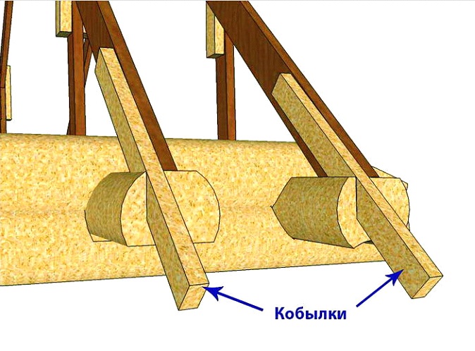
– rafter legs installed in pairs. They become the main load-bearing parts of the entire roof system - it is the rafters that determine the steepness of the slopes, will be the basis for attaching the sheathing, roofing, and if the roof is planned to be insulated, then also the entire thermal insulation “pie”. To make rafter legs, high-quality boards or timber are used; round timber can also be used. The cross-section of lumber, which will be sufficient to guarantee withstand all possible loads, will be discussed below. The rafters can end at the mauerlat, but more often they extend beyond the perimeter of the walls of the house, forming a cornice overhang. However, lighter parts can also be used for this - the so-called “fillies”, which are used to extend the rafter legs to the required overhang width. 3
- ridge run. It could be a beam, a board, or even a composite structure. The purlin runs along the entire line of the ridge and serves to reliably connect the upper points of paired rafter legs, connecting all rafter pairs in order to impart overall rigidity to the entire roof structure. In various roof options, this purlin can be rigidly supported by racks, or linked only to the connection node of the rafter legs. 4
– tightening (contracts, crossbars). Horizontal reinforcement parts of the system, additionally connecting paired rafter legs to each other. Several puffs located at different heights can be used. 5
– floor beams, which will serve as the basis for installing the floor in the attic and the ceiling on the side of the room. 6
- and this beam simultaneously serves as a bench. This is a beam that runs along the entire length of the roof, which serves as a support for installing additional reinforcement parts for the rafter system. The beam can be installed as shown in the figure (like a floor beam), or it can be rigidly laid on a permanent partition inside the building. 7
– racks (headstocks) – additional vertical supports of the rafter legs, preventing them from bending under the influence of external loads. The racks at the top can rest against the rafters themselves, or into an additional purlin that longitudinally connects the rafter legs at a certain height. 8
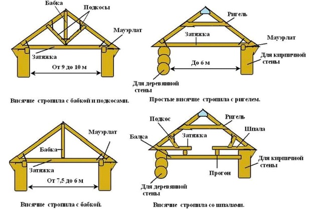
– struts. Often, when the rafter legs are long, their load-bearing capacity is not enough, and reinforcement with racks alone does not provide the necessary strength. In these cases, diagonal reinforcing elements are used, resting on the bottom of the beam, creating an additional support point for the rafters. The number of struts and their installation location may vary in roofs of varying degrees of complexity. Gable roofs can be divided into two types of structures - with layered and hanging rafters. In addition, combined systems are widely used, in which both construction principles are combined. What is the fundamental difference? This rafter system design is characterized by the presence of support on the internal main partition in the building. At the upper end of this partition, a bench is mounted on which the drains supporting the ridge girder rest. Thus, the rafter legs are “leaned” onto a vertical support, which makes the entire system as strong as possible. This type of scheme is the most popular because of its reliability and relative ease of implementation. If it is possible to create an additional point of support in the center, then why not take advantage of it? True, if you plan to place living space in the attic, then vertical racks can sometimes become a hindrance. However, their presence is also sometimes “played up”, using, for example, to install an internal light partition. Depending on the number and placement of internal partitions, the design of the layered rafter system may vary. Some examples are shown in the illustration below: Fragment “a” shows the simplest option, which, by the way, on short rafter lengths (up to 5 meters) may not even have the shown struts - a row of central posts under the ridge girder is enough As the width of the building increases, the system naturally becomes more complex, and additional reinforcing elements appear - tie rods and struts (fragment “b”). Fragment “c” clearly demonstrates that the internal main wall does not have to be located exactly in the center, under the ridge. An option as shown in the illustration is also quite possible, but with the condition that the displacement of the bed relative to the ridge does not exceed one meter. Finally, fragment “d” shows how a rafter system can be supported in a large building, but with two main partitions inside. The distance between such parallel beams can reach up to a third of the width of the building. Graphically, this roof diagram can be depicted something like this: It is immediately noticeable that the rafters rest only on the lower part, and then are connected to each other at the ridge. There is no additional support in the center, that is, the rafter legs seem to “hang”, which determines the name of such a system. This feature imposes certain restrictions on the use of hanging rafters - usually this scheme is practiced when the distance between the load-bearing walls to which the Mauerlat is attached is no more than 7 meters. The installed puffs only partially relieve the load from the external walls. The illustration below shows several options for a hanging system. However, some of them can rather be classified as combined. Fragment “d” - hanging rafters are connected to each other by a tie at the level of the mauerlat or fixed to a powerful floor beam, forming a triangle with it. There are no other reinforcing parts. A similar scheme is acceptable with a distance between walls of up to 6 meters. Option “w” is for a house of the same size (up to 6 meters). The tie (bolt) in this case is shifted upward, and is often used for lining the attic ceiling. Options “e” and “z” are designed for a span between walls of up to 9 meters. Multiple tie-downs may be used (or a top tie-down in combination with a bottom joist). Another approach is to install racks under the ridge girder, similar to the layered system. Only, as the lower point of support, it is not the support on the main partition that is used, but the racks are supported by a tie or a floor beam. It is already difficult to call this option purely “hanging”, since here it is clearly a combination of parts from both designs. To an even greater extent, this combination of two schemes is expressed in the “and” option, which is designed for large spans, from 9 to 14 meters. Here, in addition to the headstock, diagonal struts are also used. Often such trusses are assembled on the ground, and only then they are lifted and installed in place, connected to each other, thereby forming the entire roof frame. So, when preparing for the construction of a gable roof, it is necessary to study the principles of the design of a particular system, evaluate their advantages and disadvantages, choose the optimal one for your conditions and draw up a graphical working diagram. It will be needed both when purchasing the necessary material and for carrying out the installation work itself. However, drawing up a drawing must still be preceded by some calculations. Let's take another look at the schematic diagram of a gable roof to highlight the parameters that will need to be calculated. So, in the calculation process we will need to decide on the following values. The initial data is the length of the side of the house along the gable part (highlighted in blue - F), and the length of the house along the ridge (purple - D). It is assumed that the owners have already decided in advance on the type of roofing - since there will be certain restrictions on the steepness of the roof slopes. (angle a). chainsaw The steepness of the slopes can be determined by the owners according to various evaluation criteria: Calculating the height of the ridge above the plane of the ceiling (mauerlat) is not difficult. The vast majority of components of any roofing system are based on a triangle, which, in turn, obeys strict geometric (more precisely, trigonometric) laws. So, in our case, the width of the roof along the gable line is known. If the roof is symmetrical, then the ridge will be placed exactly in the middle, and for calculations you can simply divide the width F by two (the base of the triangle f =F/2). For asymmetrical slopes, you will have to project the top of the ridge onto line F, and measure the distances f1 and f2 from it to the edge of the triangle (to the Mauerlat) on each side. Naturally, in this case the slope of the slopes will be different. N =f×tga In order not to force the reader to look for tangent values and carry out calculations manually, below is a calculator in which the necessary tabular values have already been entered. 03.11.2017
In low-rise buildings, attics are usually used pitched roofs on wooden rafters with sheathing. Slope roofs are taken depending on the roofing material and the area of construction. The minimum slopes for steel roofs are 14°, for tile roofs – 27°, for corrugated asbestos-cement sheets – 18°. In areas with heavy snow cover, roof slopes of more than 30° should be accepted. The shapes of attic roofs are determined by the outline of the building in plan and the desire for architectural expressiveness. Roofs can be single-pitched, gable (most often used), hipped (hip, hip, half-hip) or multi-pitched. Drainage from the roof can be unorganized or organized. With organized drainage, the number of drainpipes is taken at the rate of 1-1.5 cm 2 pipe cross-section per 1 m 2 of roof. The optimal distance between drainpipes is 15-20 m. The removal of the roof eaves with unorganized drainage should be at least 500 mm, with organized drainage - at least 300 mm. The load-bearing structures of the roof consist of rafters made from logs, beams or boards. The choice of roof rafter scheme is made depending on the width of the building and the nature of the location of the internal walls (supports), in accordance with the roof plan. If there are internal load-bearing walls in the building plan, use layered rafters, the main load-bearing elements of which - rafter legs - work like inclined beams, the upper end resting on the ridge girder, and the lower end on the mauerlat of the external walls. The maximum length of rafter legs is no more than 6.5 m. If there are no intermediate supports in the building, then hanging rafters, which are the simplest type of rafter truss, where inclined rafter legs transmit thrust to a horizontal tie. The cross-section of rafter elements is taken constructively, by analogy with typical parts and textbook data. To avoid condensation and freezing of the insulation on the attic floor, it is necessary to ensure through ventilation of the attic through dormer windows. Particular attention should be paid to the location of the mauerlats, purlins, racks, elaboration of nodes and linking the interfaces of individual roof elements with each other. The gable roofing system is a classic mansard roof design. They belong to the most common type of engineering solutions - gable. Important! Broken mansard roofs are variations of gable roofs. They can be located symmetrically or asymmetrically, on one or two levels. Optimal tilt angle two pitched roof
The structure consists of the following parts:
Horse. The upper part that will connect the 2 slopes.
Rack. An installation used to redistribute weight from the top to the bottom of the roof. It must be made from quality materials.
Sill. A beam located horizontally. Connects the rack and the load-bearing wall.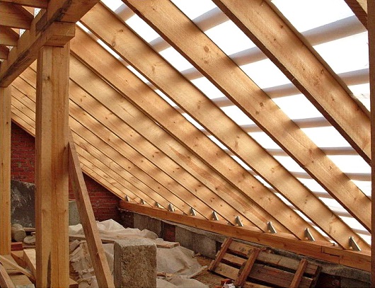

Rafter leg. These elements form a visible outline in the shape of a triangle. Serve to hold the roofing covering. The heavier it is, the more often it is necessary to lay rafters.
Fillies. Boards that extend the rafters. Necessary for creating an overhang from a gable roof, which according to building codes must be at least 0.5 m.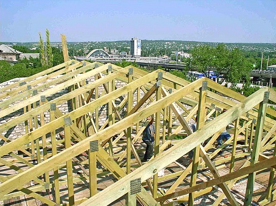
It is quite possible to complete a gable roof and the drawing on your own. All elements can be constructed in several ways. The difference is the rafter system used for construction. There are the following types of rafters: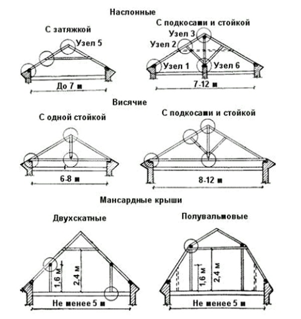
Any element of the house must be created, understanding how it will all look as a result. For clarity, a drawing is created, and so that everything fits perfectly, it is calculated in advance. The plan takes into account the length of the roof along the ridge, the length of the slopes, and the length of the plumb lines is shown separately. The angle of inclination of the roof is determined. The angle is determined taking into account the following points:Roof construction

To erect a roof, you must follow the plan:
Do not forget that a reliable roof, built with your own hands, is a guarantee of the safety of property in the house. You shouldn’t neglect its construction, so that you don’t have to make complex repairs later.What you need to know to develop a rafter plan


Development of a rafter plan

General structure of a gable roof
Basic Concepts
Structural elements of a gable roof truss system

 To form the eaves overhang, the rafters are extended with “fillies”
Some differences between the hanging and layered gable roof systems
Layered rafter system


Hanging rafter system


Calculation of the basic parameters of a gable roof rafter system

Chainsaw prices
We calculate the steepness of the slope and the height of the ridge

How to draw a roof plan. Subtleties of preparing a pitched roof plan. Stages of drawing up a drawing
- Danish roofing - combines in its design a gable and hip roof;
- half hip roof.

Hip roof rafter system
Hip roofing system – hipped roof, consisting of four isosceles triangles, closing their vertices in one place. Very well suited for square buildings. A necessary condition for the construction of such a structure is to maintain the symmetry of all elements. The multi-gable roofing system is a complex multi-angle structure. May be at different levels. Similar system distributes the load evenly over the roof surface. It has a large number of internal and external corners slopes with different values, as well as a large number of ribs.Dome (conical) roofing system - suitable for round structures. It is extremely rarely used in the construction of attic houses. But it looks great when building round towers.

Advantages and disadvantages of pitched roofs
The most simple option The installation includes a pitched roof. Reinforced concrete slabs can be used as construction material. However, a more common installation option is using a rafter system. Advantages of single-pitch truss roofing structures:
- You can do the installation yourself.
- Light weight design. Suitable for houses with lightweight foundations.
- It is mounted both on high-rise buildings and structures, and on small outbuildings on a private plot.
- It's easy to equip an attic.
- In open, windy areas, single-pitched structures with small angle tilt
To the disadvantage single-pitch structures relate:
- Low resistance to snow loads.
- Increased waterproofing to prevent leaks. Constant seasonal inspection and repair of small cracks and holes.
- Bulky appearance designs.

One of the simplest roofing structures is a pitched roof; even slightly experienced builders can construct it.
The most optimal tilt angle pitched roof is an angle of 45 degrees. It is recommended to construct such roofs in southern, windy, dry areas. It is highly not recommended to install a pitched roof in the northern snowy regions.
Rules for installing the rafter system
Rafter roofing systems are erected according to following rules:
- The cross-section of the beams cannot be less than 100x100 mm.
- Mandatory installation of waterproofing.
- Load-bearing units fixed with brackets must be additionally secured with steel strapping.
- The humidity of wooden elements should not be higher than 10%.
- All wooden elements are necessarily treated with an antiseptic and mosquito repellent.
Important! The best rafter material is a needle. It is most resistant to atmospheric influence climatic environment.
Additionally, wooden elements are coated with fireproofing agents. General installation diagram of the truss roofing system:
- arrangement of the frame;
- installation of rafters.
The rafter roof structure is tightly and securely fastened. Then stepped wall recesses are installed. After this, work on thermal insulation and waterproofing of the roof is carried out. After their completion, they begin to install the sheathing and lay the selected roofing covering. Then mortise or dormer dormer windows are installed and interior and exterior finishing work is carried out.

Construction of a house with an attic roof
Stages of installation of the rafter frame
- The top beam is laid. All elements are fastened with staples and tied with steel. This will be the rafter frame.
- Installation of the Mauerlat. This system is the main one for the entire attic roof. Boards 50 mm thick and beams 100x150 mm are used. Along the perimeter of the walls, timber is strengthened and sheathed with boards, additionally tied with steel.
- A layer of waterproofing is placed under the beams.
- The rafter legs are being erected. Marks are applied to the mauerlat in increments of 15 cm and the beams are nailed.
- The edge rafter legs are attached to the pediment. It is very important at this stage that the edge of the rafters forms a straight line.
- A leveling rope is attached to the rafters and the remaining rafters are installed.
- The legs are connected together. The ridge beam is attached.
The rafter roofing system is completed. All that remains is to arrange the sheathing, lay a hydrobarrier and insulation. The roof is installed. Installation of the roof truss system https://www.youtube.com/watch?v=gm9xv9JLozQ
Stages of drawing up a project drawing
A roof drawing for an attic begins with choosing its shape, determining the cross-section of the rafters and the installation step.
- To determine the size of the rafter legs, the following parameters are taken into account:
- slope angle;
- roof covering material;
- climatic features of the area in which construction is taking place.
- The next step is to determine the number of rafters. In terms of design, the truss roof structure can be either sloping or hanging. Before designing, it is necessary to select the type of structure.
- Calculation of roof sheathing. Highlight:
- continuous bitumen roll covering;
- ordinary sheet (wavy) coating.
- The number of parts for fastening and other auxiliary thrust elements is calculated.

Mansard roof with layered and hanging rafters, with the bottom of the rafters extending beyond the wall
The drawing must include not only a visual design of the roof structure, but also contain the following data:
- joining the roof to the parapet using a clamping profile;
- joining the roof to the parapet without a clamping profile;
- connection diagram of the ramps;
- layout mansard roof with door opening;
- calculation of the number of wooden elements building materials and the amount of roofing;
- equipment for drainage and snow retention elements.
Important! If you align the angles of inclination of the upper and lower slopes of the attic roof, then in appearance it will resemble the classic design of a gable roof. At the same time, the design of the load-bearing structure itself will remain unchanged in the standard version, which is used for broken roof structures.
When drawing a sloping mansard roof, it is necessary to carefully calculate the dimensions of all structural elements. It is also necessary to remember about the reliability, durability and safety of the roof in the operation of the house. Calculation diagram of the attic roof https://www.youtube.com/watch?v=RWu2HiFXGpM
Drawing executors
Each home is individual. Therefore, the drawing of a broken roof structure is carried out individually, taking into account the characteristics of the region. Of course, you can draw a roof drawing yourself if you are one hundred percent confident in your own expertise. SNIP standards when drawing up a roofing project are used by many construction design organizations. This helps avoid accidents. That is why it is recommended to delegate the work of drawing up the drawing to specialist developers. Construction of an attic multi-pitched roof https://www.youtube.com/watch?v=LxeBA1cIkIw
When building a private house, it is important to think through all the nuances that may arise during the work process, as well as initially determine what the appearance of the finished structure will be. This can be done by using the services of an experienced designer. But at the stage of creating the drawing, not only the type of foundation and area of the future house is determined, but also the type of roof that will be used. Remember that no house will last long, and living in it will never be comfortable, if you do not carefully plan and arrange the roof. Before starting work on creating a roof, it is necessary to design it and also calculate the area of the structure. Specialists in construction industry They claim that if you approach this issue correctly, installing a roof will not only be quick, but will also make installation work much easier and cheaper. It is extremely important to correctly determine the main elements of the section, so that when implementing the project you do not need to make any adjustments or changes, redoing everything all over again.
After developing the scheme, it is necessary to decide on the most appropriate material that will be used to create the roof of the building. Do not forget that this range of work is strictly regulated. regulatory requirements current standards. In this article we will look at everything you need to know when arranging a roof, as well as exactly how a plan should be created flat roof.
General information about the design of the project
The graphical part of the calculations must necessarily visualize the entire range of work being carried out. The roof plan is provided to the customer flat roof design drawing, certification, as well as other necessary documentation, if necessary for the implementation of the project. Today, a roofing scheme must be created if the building is equipped with an external drain. If you decide to give preference internal type, and the structure itself is not capital, then you can refuse to create a technical drawing. Thanks to the top view of the house, it is easy to determine the geometric characteristics of the floor, installation features of load-bearing structures, as well as other components of the object.

As a supplement to the drawings, there is a diagram of the arrangement of the pediment, which clearly lists the design parameters. If the project requires trimming of sheets, it is important to provide information about this as well. You should take a particularly responsible approach to creating drawings of a pitched roof, which make it possible to visualize the dimensions of the sheets, as well as the consumption of the material that will be used.
Advantages of a flat roof
Of course, all the people who decided to take on construction own home, are often faced with the problem of choosing the most optimal type roofs. It is safe to say that the use of a flat roof in a construction project will make the appearance of the finished house truly stylish and modern. In addition, this type of design is easy to install and is considered a budget option. But do not forget about one significant drawback of this roof, which is that it is highly susceptible to the influence of environmental factors and requires careful waterproofing work.

What you need to know about flat roofing
Below we list the main requirements that are put forward to this type designs, namely:
Since precipitation should under no circumstances accumulate on the roof surface, there must still be a slope. To ensure the durability of the structure and the reliability of the roof itself, it must be no less than 2%. The most the best option is 10-15 degrees.
If your area is characterized by prolonged and heavy rains or a large amount of precipitation in the cold season, then in this case slope alone cannot be done. It is important to consider creating a complete drainage system. It can be both external and internal. One riser can serve an area of about 150-200 square meters.
In suburban housing construction, external drains are often created using special overflow windows, which are installed at the level of the roof storm drain. If the drain lines do not intersect, it is strongly recommended to show the perimeter of the facade in the roof plan.

It is important to note that projects of private cottages often do not contain information about the angle of inclination; in this case, to correct the designer’s error, there is no need to redo the entire work again, but simply need to form the inclination using various bulk materials, as well as screeds or polystyrene slabs.

Subtleties of preparing a pitched roof plan
To begin with, it is worth noting that a pitched roof is a roof that is a prefabricated structure of sheets with a slope of no more than 10%. Considering design features, construction experts distinguish two types of roofing - with or without an attic. The most common and popular option is a roof consisting of 2 slopes. This design can be applied to any building. In cross section it resembles a triangle, and ready-made diagram should contain detailed information about indicators such as: length, location of each element, as well as cross-section. It is extremely important during the design process to decide on the principle of fastening the units, and also to record this in the regulatory and technical documentation for the facility.
in this case, the arrow is made with main lines 2...4 mm long, drawn at an angle of 45° to the extension line. The marks are located to the left of the facade along one vertical line; the shelf above which the numerical value of the mark is placed must be rotated away from the image.
9. Outline the facade with solid thin lines; draw the ground level line as a solid main line and extend it beyond the contours of the facade by 15...20 mm.
10. Above the completed façade, write the name of the image, in which indicate the extreme axes, for example “FACADE 1-9”
An example of the façade is given in the appendix. 4.6.
The rafter plan should be carried out in M 1:200
1. Draw coordinate axes:
Their designations.
The distance between them.
Distance between extreme axes.
2. Draw an internal border outer wall, observing the binding.
3. B outer side from coordinate axis set aside the width of the cornice.
4. We lay the Mauerlat along the perimeter of the building on the inner edge of the outer wall.
5. In the corners of the building we install crossbars to support the diagonal rafter legs.
6. We draw diagonal rafter legs from the corners of the building at an angle of 45°.
7. We lay the lower purlin (laying) along the internal walls; we lay the lower purlin above them.
8. We lay out the rafter legs, starting from the support unit after 1200-2000 mm, resting them with one end on the mauerlat.
9. We install the racks starting from the support unit, after 3-6 m.
10 Diagonally rafter legs We lay the shortened rafter legs in a checkerboard pattern.
11. To install the cornice, we attach a filly to each rafter leg and... and to the diagonal rafter legs on both sides.
On the plan of the rafters, we depict with a dotted line the ventilation and frame for the dormer windows.

Figure 10 - Rafter plan
An example of the rafter diagram is given in the appendix. 4.7.
Execute the roof plan in M 1:200
Pitched roof plan:
2. Using thin dashed lines, draw the outer edge of the outer walls, keeping them aligned with the axes.
3. Show the lines of the roof edges (slopes), observing the amount of overhang (overhang) of the cornice.
4. Show the lines of the sloping ribs (at an angle of 45°) and valleys, the line of the roof ridge.
5. Draw dormer windows that serve as access to the roof, for lighting and ventilation of the attic.
6. Draw ventilation pipes in projection connection with the floor plan.
7. Draw, if required, a roof fence around the perimeter. Fencing is installed for safety repair work and clearing the roof of snow. The height of the fence is at least 0.6 m. Fences on the roof should be provided with:
In buildings with a roof slope of up to 12% inclusive, the height from ground level to the cornice (parapet) is more than 10 m;
In buildings with a roof slope of more than 12% and a height of more than 7 m;
For used flat roofs, regardless of the height of the building.
Fences are made of round or strip steel in the form of welded gratings mounted on steel posts with struts. Steel posts and struts are installed on top of the roof and nailed to the roof sheathing. Under the legs of the racks and struts for reliable waterproofing install special gaskets made of sheet rubber.
8. An external organized drainage system should be designed and drainage gutters and drainpipes should be drawn on the roof plan. The distance between external drainpipes should be no more than 24 m; The cross-sectional area of the drainpipe should be taken at the rate of 1.5 cm 2 per 1 m 2 of roof area (SNB 5.08.01-2000. Roofs).
Calculate quantity drainpipes. Set the diameter of the drainpipe D, For example D= 13 cm.
Find the cross-sectional area of the pipe S pipes according to the formulas:
S pipes = πR 2
or S pipes = πD 2 /4, if pipe round section,
S pipes = 3.14×13 2 /4 = 132.665~133 cm 2
Pipes of rectangular cross-section can also be accepted. Calculate the roof area S roofs.
Calculate how much roof area one drainpipe will serve:
1.5 cm 2 pipes - 1 m 2 roofs,
133 cm 2 pipes - X m 2 roofs,
X = 133/1.5 = 88 m2.
Number of drainpipes:
N pipes = S roofs /88.
Place this number of drainpipes evenly around the perimeter of the roof in characteristic places; draw them on the plan, attach the axes to coordination axes.
Make your own decision about what kind of gutters you want (wall-mounted or hanging).
Flat roof plan:
1. Draw the coordination axes, their designations, the distances between them and between the extreme axes.
2. Draw the parapet of the external walls, the parapet of the wall at the point of difference in height of the building.
3. Draw ventilation pipes in projection connection with the floor plan.
4. Draw a shaft for access to the roof.
5. Draw fire escapes if necessary.
Each section of the roof, limited by walls, must have at least two water intake funnels. Number of funnels N assume that one funnel serves at least 800 m2 of roof:
N=S roofs /800.
If the area of the unused roof is less than 700 m2, and the area of the operated roof with landscaping is less than 500 m2, it is allowed to install one funnel with a diameter of at least 100 mm (SNB 5.08.01-2000).
7. Place the funnels along the roof surface so that the rainwater drainage risers pass through the auxiliary rooms of the building ( staircases, bathrooms, vestibules, corridors, etc.). Installation of drainage risers in thick walls is not allowed. Draw funnels as circles, their axes tied to the nearest coordination axes of the building.